- Catalogs
- Infranor Group
- PacHP_SF02_operating_en_1.6


PacHP_SF02_operating_en_1.6

PacHP_SF02_operating_en_1.6
This document serves as the operating manual for the XtrapulsPacHP SF02, emphasizing its safety functions. It details various safety functions such as SS1, SS2, SOS, SLS, SDI, SBC, SLP, and SPR, all certified to SIL2. The SF02 safety board is compatible with servo drive versions including EtherCAT, CANopen, and PROFINET buses. The STO function, certified to SIL3, is standard and operable without the safety board.
The SF02 safety board offers advanced safety functions:
- SS1 (Safe Stop 1) SIL2: Initiates monitored deceleration and switches off motor torque.
- SS2 (Safe Stop 2) SIL2: Initiates monitored deceleration and monitors standstill position.
- SOS (Safe Operating Stop) SIL2: Monitors standstill position.
- SLS (Safely-Limited Speed) SIL2: Monitors motor speed within predefined limits.
- SLP (Safely-Limited Position) SIL2: Monitors machine's absolute position within predefined limits.
This section outlines the commissioning steps for the drive, including safety guidelines, software tools, and parameter settings. It covers the use of the "Optio Drive Assistant" for drive commissioning and configuring safety functions using the Safety Tool software.
This chapter discusses acceptance and periodic inspection procedures for safety functions like STO, SS1, SS2, SOS, SLS, SDI, SLP, and SPR.
The technical data section provides information on operating environment conditions and safety data, including vibration and shock limits during transport.
The document includes figures and tables providing detailed technical specifications, configuration parameters, and timing diagrams for safety functions and components.
The document outlines various safety functions integrated into the XtrapulsPacHP SF02 drive system, including Safe Torque Off (STO), Safe Position Referencing (SPR), Safe Direction (SDI), and Safe Brake Control (SBC), all certified to SIL2. Safety functions can be controlled via dual-channel safety inputs or a Safety bus.
The safety board parameters are configured using the Safety Tool software, requiring the drive to be in STO mode for access. The safety board includes two 24V supply outputs with test pulses for short-circuit detection and three non-safety-certified status outputs.
The design and testing of the safety option SF02 comply with European Directives and product standards such as EN 61800-5-2:2017 and IEC 61508 series, ensuring functional safety of electrical/electronic systems.
The document provides detailed technical specifications for the safety board, including drive logic supply voltage, safe 24V supply output, safety brake supply input, and position sensor requirements.
The ordering code for drives and connector sets is detailed, specifying options for drive versions, voltage ranges, current ratings, and mounting versions. Dimensions for various drive models are provided.
The document describes the connectors for resolver and safety functions, detailing pin functions for safety inputs and status outputs.
The document outlines specifications for various safety inputs and outputs, including opto-coupled safety inputs and logic outputs.
Procedures for connecting components such as the safety brake, encoder, serial link RS232, fieldbus connectors, and power connectors are mentioned.
The document describes safety functions compliant with IEC 61800-5-2:2017, including STO, SS1, SS2, SOS, SLS, SDI, SLP, SPR, and SBC.
Operating modes for the STO safety function and the safety board are detailed, including initialization, normal operation, warning, torque off, and fault states.
Error messages are categorized into faults and monitoring alarms, with descriptions of their impact on the system and reset conditions.
Safety functions can be controlled via dual-channel logic inputs or the safety bus.
Recommendations include using a compliant position sensor for safety function monitoring and configuring the safety card appropriately if the resolver does not meet specifications.
This document is an operating manual for the XtrapulsPacHP SF02, focusing on the description and management of safety functions.
The manual describes several key objects:
- Safety Control Word (0x2914): Responsible for activating safety functions.
- Safety Status Word (0x2915): Reflects the current state of safety functions.
- Safety Bus Control Word (0x290D): Specifically for functions controlled via the safety bus.
The document outlines the configuration of safety inputs and outputs.
This feature prevents unintended machine movement after start-up or a stop condition.
This functionality allows resetting of monitoring alarms triggered by safety function execution errors.
The manual provides detailed instructions on configuring and monitoring safety functions within the XtrapulsPacHP SF02 system, ensuring safe operation and compliance with safety standards.
When a fault is detected, the 'Error' bit in the safety status word is set. To reset the error, a rising edge in the 'Error Ack' bit in the safety control word is required.
The STO function is a basic safety feature of the XtrapulsPacHP drive, achieving SIL3 level.
Parameters include control selection, status output selection, restart legacy behavior, and restart acknowledge behavior.
The SS1 function initiates a controlled stop by monitoring the deceleration ramp and activating the STO function.
Parameters include control source selection, operation selection, and profile generator selection.
The SS2 function initiates and monitors a deceleration ramp, activating the SOS function.
The SOS function ensures the motor remains at a standstill with torque enabled.
The SLS function monitors motor speed, ensuring it remains within safe limits.
The SDI function monitors motor rotation direction, maintaining it in a safe state with torque enabled.
The SDI function involves parameters for control selection, direction status output, and activation state output.
The SBC function manages an external brake to maintain motor standstill.
The SLP function monitors the motor's absolute position within defined limits.
The SPR function defines the safe absolute position, executed once before SLP activation.
1. Safe Absolute Position Channels: Two channels with Signed32 data type.
2. Safe Position Referencing States: Unsigned16 data type.
3. Safe Position Referencing Cancel Command: Unsigned32 data type.
Safety functions are prioritized by number, with the smallest number having the highest priority.
The resolver evaluation involves monitoring motor trajectory using a resolver with a safety architecture.
Key diagnostics involve monitoring amplitude, frequency, vector length, and circuit conditions.
The XtrapulsPacHP-et drives with SF02 safety board support Safety-over-EtherCAT for controlling safety functions.
The document provides detailed technical specifications and procedures for managing safety functions and resolver diagnostics in the XtrapulsPacHP SF02 system.
The FSoE slave address of the drive must be set using two rotary switches, A1 and A2.
During startup, the FSoE Master sends communication parameters to the drive.
The FSoE Master manages the state machine of the FSoE slave.
The FSoE frame is transported via EtherCAT PDOs.
FSoE communication setup and diagnosis involve read-only objects accessible through the SDO communication channel.
Objects like 0x1700 and 0x1B00 define the PDO mappings.
Object 0xEA00 provides connection state and diagnosis information.
- Device Safety Address: The FSoE address is defined by Object 0xF980.
- Safety Guidelines: Conduct a risk analysis before commissioning.
- Software Tools: Use OPTIO Drive Assistant for parameter setting and Safety Tool for configuring safety functions.
- Safe Drive Parameter Setting: Parameters are managed via a 'safe parameter file'.
- Basic Principles of Parameter Setting: Offline and online operations are protected by passwords.
- Password Management: The drive uses 'file' and 'access' passwords.
- Preparing the Commissioning: Ensure the drive is correctly installed and wired.
- Drive Commissioning with OPTIO Drive Assistant: Configure position sensors and safe stop parameters.
- Safety Functions Parameter Setting: Use Safety Tool to create and transfer the 'safe parameter file'.
- Safety Drive Replacement: Follow specific steps for replacing a drive.
- Failure Mode Analysis: Safety Tool software controls parameter input to prevent errors.
The document outlines the importance of file integrity and security in safety modules.
The troubleshooting section provides detailed error codes and solutions for various issues.
This section describes the acceptance and periodic inspection processes for safety functions.
Detailed procedures for testing safety functions like STO, SS1, SS2, and others are provided.
The technical data section specifies operating environment conditions.
The drive must be installed without obstructing the heatsink and fan.
Vibration levels must comply with IEC 60721-3-3:1995, class 3M1 for fixed equipment.
Abnormal conditions diverging from IEC 60146-1-1 standards must be specified by the purchaser.
Both normal and abnormal conditions apply to all stages of equipment use.
Equipment must be stored according to IEC 60721-3-1:1997 standards.
Risks include exposure to water, altitude, corrosive agents, and rodents.
Equipment can be transported under IEC 60721-3-2:1997 conditions.
Safety characteristics for the safety board include a lifetime of 20 years, SIL2 safety integrity level.
Infranor provides customized motion solutions with a global presence in various countries.
Catalog excerpts
XtrapulsPacHP SF02 Operating manual
Open the catalog to page 1
XtrapulsPacHP SF02 - Operating manual ! This is a specific manual describing the Safety function of the XtrapulsPacHP servo drive range having output capability suitable for driving AC brushless sinusoidal servo motors. Please see also: o XtrapulsPacHP User Guide for the operation of the drive (commissioning, configuration, ...). o XtrapulsPacHP Installation Guide for the hardware installation of the drive (mounting, wiring, …). o EtherCAT fieldbus interface manual for the XtrapulsPacHP-et version. o PROFINET fieldbus interface manual for the XtrapulsPacHP-pn version. o XtrapulsGDPS manual, for...
Open the catalog to page 2
XtrapulsPacHP SF02 - Operating manual All electrical industrial automatisms which lifetime is coming to its end are Waste Electronic and Electrical Equipment (WEEE) according to article R543-172 of the French Environmental Code. WASTE DISPOSAL This symbol indicates that INFRANOR devices shall be eliminated by selective disposal and not with household waste. WEEE classification of the INFRANOR products Category 9: Monitoring and control instruments In accordance with the Decree nr. 2012-617 of May 2nd, 2012, which specifies the provisions related to the professional EEE manufacturers' obligations,...
Open the catalog to page 3
XtrapulsPacHP SF02 - Operating manual
Open the catalog to page 4
XtrapulsPacHP SF02 - Operating manual
Open the catalog to page 5
XtrapulsPacHP SF02 - Operating manual
Open the catalog to page 6
XtrapulsPacHP SF02 - Operating manual
Open the catalog to page 7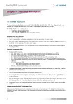
XtrapulsPacHP SF02 - Operating manual 1.1 - SYSTEM OVERVIEW This manual describes the Safety functions (SS1, SS2, SOS, SLS, SDI, SBC, SLP, SPR) of the XtrapulsPacHP drive equipped with the optional safety board (SF02 option). These safety functions are SIL2 certified. The SF02 safety board is available with the - -XtrapulsPacHP-pn (PROFINET bus) servo drive versions. The drive range XtrapulsPacHP > The STO function SIL3 is available as standard and can be used without the safety board. > Two inputs STO1\, STO2\ are available for the STO function activation. This allows switching off the motor...
Open the catalog to page 8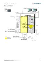
XtrapulsPacHP SF02 - Operating manual Figure 1 - System Overview Software Tool Safety card Numerical controller With FSoE interface Optio Software Safety inputs SAFE 24V supply SAFETY FUNCTION STATUS PDS(SR) SAFETY CARD SIL2 PacHP DRIVE PDS Serial_comm Trajectory Controller Safety Controller Pulse_disable Power stage Motor Resolver Safety card Safety Brake supply SBR_24V/SBR_0V 3 STO function Safety BRAKE (SBC) Chapter 1 - General description
Open the catalog to page 9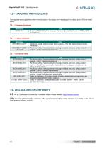
XtrapulsPacHP SF02 - Operating manual The regulations and guidelines which form the basis of the design and the testing of the safety option SF02 are listed below. C€ : The EC Declaration of conformity is available on the Infranor website: https://infranor.com/en/ TUV: The TUV certificate for the conformity of the safety functions with the safety standards is available on the Infranor website: https://infranor.com/en/ Chapter 1 - General description
Open the catalog to page 10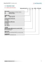
XtrapulsPacHP SF02 - Operating manual 1.4 - ORDERING CODE 1.4.1 - Ordering code of the drives Drive version ak: Analog interfaces and CANopen fieldbus et: EtherCAT fieldbus pn: PROFINET fieldbus Voltage range 230: Voltage range 230V 400: Voltage range 400V Current ratings for 230V drives 05 = 5Arms 11 = 11Arms 17 = 17Arms Current rating for 400V drives 08 = 08Arms 20 = 20Arms 45 = 45Arms 100 = 100Arms 200 = 200Arms OPTIONS Mounting version (400V range only, except for 200A) PT: Push-through version CP: Cold plate version Safety option SF02: safe motion monitoring (PacHP-ak, -et and -pn only)...
Open the catalog to page 11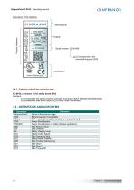
XtrapulsPacHP SF02 - Operating manual ->23 corresponds to the manufacturing year 2023 1.4.2 - Ordering code of the connector setsFC-SF02: connector kit for safety board SF02 Contains: - S1 connector for the safety functions activation and status: B2CF 3.50/20/180 (Weidmuller) - S2 connector for safe brake output: BLZ5.08/04/180B (Weidmuller) Chapter 1 - General description
Open the catalog to page 12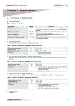
XtrapulsPacHP SF02 - Operating manual 2.1 - TECHNICAL SPECIFICATIONS • Product identification: Table 1 - Product identification • Position sensor: Resolver.
Open the catalog to page 13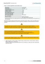
XtrapulsPacHP SF02 - Operating manual Table 5 - Technical specification of the position sensor Manufacturer Resolver type Transformation ratio Supported resolver pole pairs Excitation amplitude Excitation frequency Max. excitation output current Phase shift (include cable) Max. resolver cable length Minimum input impedance ZRO = √ݑ2 + (Űݐ߰ݑ)2 Resolver cable type Shielded twisted pairs. 360° shield connection at both sides Mounting requirements may be safety relevant and must be observed to be consistent with error assumptions and their monitoring. Monitoring the resolver signals has specific...
Open the catalog to page 14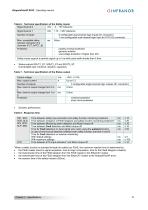
XtrapulsPacHP SF02 - Operating manual Table 6 - Technical specification of the Safety inputs *When a safety function is activated through the safety bus FSoE, the maximum reaction time is determined by: • the FSoE master (time for signal acquisition, time for logic computation, time for the FSoE telegram creation). • the transmission time of the FSoE telegram from the FSoE master to the EtherCAT master. • the transmission time of the FSoE telegram from the EtherCAT master to the XtrapulsPacHP drive. • the reaction time of the safety module (<20ms).
Open the catalog to page 15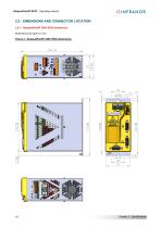
XtrapulsPacHP SF02 - Operating manual 2.2.1 - XtrapulsPacHP 230V SF02 dimensions Dimensions are given in mm. Figure 2 - XtrapulsPacHP 230V SF02 dimensions
Open the catalog to page 16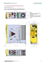
XtrapulsPacHP SF02 - Operating manual 2.2.2 - XtrapulsPacHP 400V / 08A to 45A SF02 dimensions Dimensions are given in mm. Figure 3 - XtrapulsPacHP 400V / 08A to 45A SF02 dimensions Note: This bottom view is the one of the 400/45 drive (without X10 connector). The X10 connector is only available on drives with 8A and 20A current ratings.
Open the catalog to page 17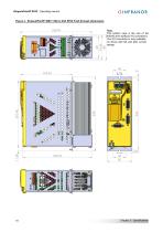
XtrapulsPacHP SF02 - Operating manual Figure 4 - XtrapulsPacHP 400V / 08A to 45A SF02 Push-through dimensions Note: This bottom view is the one of the 400/45 drive (without X10 connector). The X10 connector is only available on drives with 8A and 20A current ratings.
Open the catalog to page 18All Infranor Group catalogs and technical brochures
 XtrapulsPac_EN
4 Pages
 XtrapulsGemTemplates_e_1.4
21 Pages
 XtrapulsGem_User_Manual_v1.2.0.64
199 Pages
 XtrapulsGem_Inst_e_2.1
42 Pages
 XtrapulsGem_Inst_e_2.0
42 Pages
 SMTBSi-2Tz_en_2.1
43 Pages
 smt-100
32 Pages
 PacSimBox_d_1
1 Page
 Pac-SF01_flyer_en_18.02
4 Pages
 Pac_User_1.2.1.218
253 Pages
 Pac_Templates_en_1.9
27 Pages
 Pac_STO_Installation_en_2.2
13 Pages
 Pac_SF01_operating_en_1.6
63 Pages
 Pac_SF01_EN
4 Pages
 Pac_Installation_en_2.23
82 Pages
 Pac_flyer_en_17.12
4 Pages
 Option_CT_EMF
6 Pages
 MOVINOR_LH055_LH086_LH097_LH142
23 Pages
 ma_series
6 Pages
 GemSafeTorqueOff_en_1.1
12 Pages
 GemProgramming_e_1.1
47 Pages
 GDPS_old_version_1.1_1
11 Pages
 CD1pm_e_1.2(old)
18 Pages
 CD1pInst_e_7.2(old)
35 Pages
 CD1kInst_e_4.1(old)
40 Pages
 CD1k_CANopenProtocol_e_1.3(old)
86 Pages
 CD1a_e_7.1(old)
45 Pages
 Catalogue gamme SMT-BD1
11 Pages
 BM20A(F)v3_0
20 Pages
 BM20A(D)v3_0
20 Pages
 BF400(GB)v2_2
21 Pages
 BF400(D)v2_2
21 Pages
 BF230(GB)v2_0
23 Pages
 BF230(F)v2_0
23 Pages
 BD2m_e_2.2
69 Pages
 BD2m(GB)2.0
70 Pages
 BD2_e_3.2
53 Pages
 BD2(GB)3.1
53 Pages
 BD2(D)3.1
54 Pages
 Movinor_LH_e
4 Pages
 ma_series
6 Pages
 BD1t(GB)3.1
81 Pages
 BD1t(F)3.0
85 Pages
 BD1pInst(GB)3.0
25 Pages
 BD1pInst(F)3.0
23 Pages
 BD1pInst(D)3.0
24 Pages
 BD1pCD1pUse_e_2.4
57 Pages
 BD1m(GB)5.0
58 Pages
 BD1m(F)5.0
57 Pages
 BD1m(D)v3_3
64 Pages
 BD1k(GB)2.1
35 Pages
 BD1k(F)2.1
36 Pages
 BD1j(GB)v2_41
19 Pages
 BD1j(F)v2_4
21 Pages
 BD1i(GB)v2_21
23 Pages
 BD1i(F)v2_2
27 Pages
 BD1h(F)3.0
65 Pages
 BD1h(D)3.0
59 Pages
 BD1g(GB)v3_0
28 Pages
 BD1g(F)v3_0
28 Pages
 BD1a400(GB)v2_3
43 Pages
 BD1a400(F)v2_3
44 Pages
 BD1a400(D)v2_3
45 Pages
 BD1(GB)7.1_noPW
45 Pages
 BD1(GB)7.1
45 Pages
 BD1(F)7.1_noPW
47 Pages
 BD1(F)7.1
47 Pages
 BD1(D)7.1
45 Pages
 BD1 Katalog
11 Pages
 08ma_ms_e_01700
20 Pages
 Easy_User_5.0.1.60.2
190 Pages
 08ma_mrm_em_01575
20 Pages
 01ma_smv_e_01953
40 Pages
 PacHP-SF_Flyer_en_23.06
4 Pages
 IRD_User_Manual_en_1.2.XX.54.rev_b
216 Pages
 PacHP_User_en_1.2.8.100.b
280 Pages
 PacHP_SF01_operating_en_2.0
63 Pages
 PacHP_Installation_en_2.9
91 Pages
 PacHP_Series_Brochure
8 Pages
 PacHP_Flyer_us_20.10
4 Pages
 IRD_Installation_en_1.5
42 Pages
 GDPS_Installation_en_4.4
18 Pages
 Easy_STO_en_1.4
14 Pages
 Easy_DB_STO_en_1.2
14 Pages
 Easy_DB_Installation_en_1.4
36 Pages
 CD1pmUser_en_4.2
55 Pages
 CD1pmInst_en_8.15
40 Pages
 CD1k_CANopenProtocol_en_2.10.1.1
108 Pages
 CD1pm_ProfibusProtocol_en_1.5
50 Pages
 CD1kUser_en_2.3
26 Pages
 CD1a_en_8.17
62 Pages
 CD1kInst_en_5.16
46 Pages
 CD1_STO_en_1.8
16 Pages
 CD1_flyer_en_14.09
4 Pages
 Braking_Resistors_en_1.5
10 Pages
 XtracontrolDC2_EN
4 Pages
 Flyer_VisiTouchCNC_EN_V1.1-1
2 Pages
 XtraforsWashdown_EN-2024
2 Pages
 DataSheet_CybIO_CNC_V1.0
6 Pages
 XtraforsPrime_EN-2024
2 Pages
 XtraforsMSS_EN
4 Pages
 XtraforsMSA_EN_2024
2 Pages
 XtraforsEx_EN-2024
2 Pages
 XtraforsBR_EN-2024
2 Pages
 XtraforsBL_EN-2024
2 Pages
 XtraforsBC-ed01-vs3
4 Pages
 Manual_XtraforsPrime
46 Pages
 Drawing_1
1 Page
 Datasheet_MSS
5 Pages
 Datasheet_2
2 Pages
 Datasheet_1
4 Pages
 BLSBLT_series
2 Pages
 BL220221
2 Pages
 BL270
BL2702 Pages
 BL190
BL1902 Pages
 bl100_series
6 Pages
 bl40_series
6 Pages
 BL30
BL302 Pages
 2019-01_XtraforsFP-DSL_FR
4 Pages
 Movinor_T_EN
4 Pages
 Movinor_N_EN
4 Pages
 Movinor_Low_Voltage_EN
4 Pages
 Manual Movinor T 03-2026
46 Pages
 Manual Movinor N 03-2026
63 Pages
 XtrapulsEasy™ AC servo-drive
4 Pages
 XtrapulsCD1 AC servo-drives
4 Pages
 CybIO
CybIO6 Pages
 AC SERVOMOTORS
2 Pages
 Movinor® N AC Servomotors
4 Pages






Archived catalogs
 AN_CD1ak_AbsoluteEncoder_en_2.0
10 Pages
 AN_CD1ak_SinCosTracks_e_1.0
7 Pages
 AN_CD1pm_AbsoluteEncoder_en_2.0
10 Pages
 AN_CD1pm_SinCosTracks_e_1.0
7 Pages
 AN_DC_bus_interfacing_en_1.3
5 Pages
 CD1_EC_conformity_24.05
1 Page
 CD1_STO_conformity_19.02
2 Pages
 EtherCAT Interface_en_1.3
20 Pages
 Easy_EC_Conformity_24_10
1 Page
 GDPS_EC_conformity_24.07
1 Page
 IRD_EC_Conformity_25.03
1 Page
 PacHP_TÜV_certificate_25.07
2 Pages
 BD1c(F)v2_01
19 Pages
 BD1c(GB)v2_01
19 Pages
 BD1d(F)v2_01
25 Pages
 BD1d(GB)v2_01
25 Pages
 BD1e(F)v2_01
22 Pages
 BD1f(F)v2_01
17 Pages
 BD1f(GB)v2_01
18 Pages
 CE_conformity_Gem
1 Page
 Pac_EC_conformity_25.04
1 Page
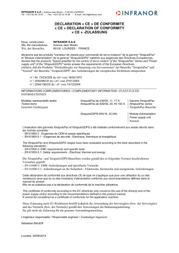 Pac_GDPS_CEconformity
1 Page
![SMT100D_e_1.01[1]](https://img.directindustry.com/pdf/repository_di/4620720/smt100d-e-101-1-1141223_1mg.jpg) SMT100D_e_1.01[1]
SMT100D_e_1.01[1]40 Pages
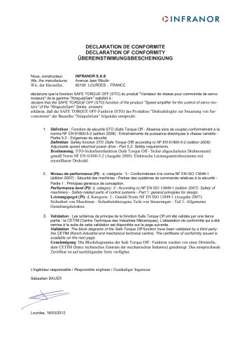 STO_declaration_Gem
2 Pages