
- Catalogs
- Infranor Group
- PacHP_Installation_en_2.9


PacHP_Installation_en_2.9

PacHP_Installation_en_2.9
- CANopen Interface: Suitable for axes controlled by CANopen fieldbus (DS402 protocol), stand-alone operation, traditional analog speed drive, and stepper motor emulation.
- EtherCAT Interface: Used for axes controlled by EtherCAT fieldbus (DS402 protocol) and stand-alone operation.
- The PacHP drive controls motor torque and speed using high-resolution position sensors, ensuring smooth motor control.
- Supports various position sensors, including resolver, incremental encoder, and absolute encoders with different communication protocols.
- Complies with multiple directives and standards, including Low Voltage Directive, Machinery Directive, Electromagnetic Compatibility, and others related to safety and environmental regulations.
- Drives are categorized by interface type (e.g., CANopen, EtherCAT), voltage range (230V, 400V), and current range (e.g., 5Arms, 11Arms).
- Options include mounting versions and safety features.
- Different connector sets are available for command, power, and motor connections, with specific kits for different voltage ratings.
- Details on operating power supply voltage, braking thresholds, EMC filters, and output current ratings for different drive models.
- Cooling options include forced air, push-through, and cold plate, depending on the model.
- Optio software tool for configuration and parameterization, compatible with Windows OS.
- Autotuning and autophasing functions for easy commissioning.
- Hiperface Encoder: Differential inputs for Data, Sin, and Cos channels with internal supply voltage of 9.5V.
- Single-turn Absolute SinCos Encoder: Differential inputs for reference pulse and channels A, B, C, D with a 5V encoder supply voltage.
- CANopen Bus: Uses RJ45 connectors with specific pin assignments for CAN-H, CAN-L, and ground connections.
- Ethernet Network: Requires minimum category 5e cables with specific shielding and length requirements.
- 24VDC Auxiliary Power Supply: Provides specifications for motor brake output and auxiliary power supply with specific current ratings for different PacHP versions.
- Power Connectors: Detailed pin functions for motor phases, DC bus outputs, and braking resistors for various voltage and current configurations.
- Analog Inputs: Instructions for connecting differential and non-differential analog signal sources.
- Sensors: Connection details for resolvers, incremental TTL encoders, and absolute encoders like Hiperface and EnDat 2.2.
- UL Standard Requirements: Specifies conditions for 24V supply and power supply protection with recommended fuse ratings.
- Grounding and Shielding: Emphasizes the importance of proper grounding and shielding for motor and brake cables.
- First Powering of the Drive: Ensure correct connections, especially for 24VDC and power supplies. Incorrect voltage connections can destroy the drive. Disable logic inputs configured with the Enable function. Verify braking resistor specifications and grounding.
- Connection of 24VDC Supply: The red Err LED should flash indicating an "Undervolt." error. Follow connection recommendations as per the guide.
- Connection of Mains Power Supply: The red Err LED should be unlit. Continuous lighting indicates a fault.
- Starting Procedure: Refer to the PacHP User Guide. Ensure safety measures to prevent uncontrolled axis movements.
- Cabinet Design: Use a cabinet with thermal boundaries for the push-through version. Ensure proper cooling and periodic cleaning of filters.
- Soft Start System: Limits inrush current at power-up. The system remains operational when powered by DC inputs. Follow integration recommendations to maximize component lifespan.
- Sizing of the Braking System: Defines the maximum duty cycle of the braking transistor. Ensure correct settings to prevent damage and faults.
- Interaction Between Operating Voltage, Inductance, and PWM Frequency: PacHP drives can operate within a wide voltage range. Specific operating voltages affect drive specifications.
- Maintenance: Regular checks are necessary for housing, cooling, dust, corrosion, and mechanical mounting. Special procedures are required after long storage periods.
- Operating Environment Conditions: Drives must be mounted in an IP54 cabinet, protected from dust and condensation. Abnormal conditions require special considerations.
- Climatic Conditions: The equipment can be transported in its standard packaging under conditions specified by class 2K3 of the IEC 60721-3-2:1997. This includes a surrounding air temperature range of -25°C to +70°C and relative moisture of 95% at +40°C. Note that certain temperature and moisture combinations may cause condensation.
- Unusual Climatic Conditions: Transport at temperatures lower than -25°C requires either reheating or removal of components sensitive to low temperatures.
- Mechanical Conditions: The equipment can be transported under conditions specified by class 2M1 of the IEC 60721-3-2:1997 standard, which includes specific vibration and shock limits. Special packaging or transport conditions are required if these limits are exceeded.
- Vibration Limits: Frequencies from 2 to 9 Hz have an amplitude limit of 3.5 mm, while frequencies from 9 to 200 Hz have an acceleration limit of 10 m/s², and from 200 to 500 Hz, the limit is 15 m/s².
- Shock Limits: Equipment with mass less than 20 kg can withstand a free fall height of 0.25 m, while equipment with mass between 20 kg and 100 kg also has a limit of 0.25 m. For equipment over 100 kg, the limit is 0.10 m.
Catalog excerpts
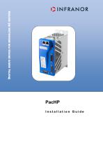
Installation Guide DIGITAL SERVO DRIVES FOR BRUSHLESS AC MOTORS
Open the catalog to page 1
This is a general manual describing a series of servo drives having output capability suitable for driving AC brushless sinusoidal servo motors. Warning Please see also: -PacHP User Guide for the operation of the drive (commissioning, configuration, ...) -EtherCAT fieldbus interface manual for the PacHP-et and -ed versions. -PROFINET fieldbus interface manual for the PacHP-pn version. -GDPS manual, for the use of the GDPS power supply unit. -PacHP SF01 Safety version operating manual -PacHP SF02 Safety version operating manual Instructions for storage, use after storage, commissioning as well...
Open the catalog to page 2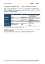
WEEE classification of the INFRANOR products Category 9: Monitoring and control instruments In accordance with the Decree nr. 2012-617 of May 2nd, 2012 which specifies the provisions related to the professional EEE manufacturers' obligations, INFRANOR France is a member of RECYLUM: eco-organization ecosystem certified for the collection, treatment and recycling of WEEE. In France, RECYLUM allows all professionals benefiting from a free collection and recycling solution, in observance of the regulation, the environment and health. Information and sorting instructions regarding INFRANOR products...
Open the catalog to page 3
PacHP installation guide OINFRANOR
Open the catalog to page 5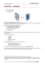
PacHP installation guide OINFRANOR PacHP drives replace the Pac drives launched in 2009. Thanks to new embedded technologies in current sensing, analog signals conversion and power calculation, the PacHP range achieves double regulation performances compared with Pac. PacHP drives ensure full compatibility with Pac drives: - All existing functionalities are still available, - Parameter files are directly compatible, - Mechanical dimensions are unchanged, PacHP all-digital drives with sinusoidal PWM control are servo drives that provide the control of brushless AC motors with a position sensor....
Open the catalog to page 7
PacHP_installation_guide With its very small dimensions, the PacHP is available in various designs: stand-alone or multi-axis version, standard forced air, push-through or cold plate cooling versions. Series PacHP drives are fully configurable in order to fit various applications. The PacHP version with CANopen interface can be used in the following application types: • • • • Axes controlled by CANopen fieldbus according to the DS402 protocol, Stand-alone operation as a motion sequencer with control by means of logic I/Os, Traditional analog speed drive with +/- 10 V command and position output...
Open the catalog to page 8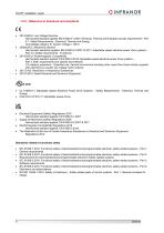
PacHP installation guide OINFRANOR 1.2.2 - Reference to directives and standards Harmonized standard applied: EN 61800-5-1:2007: Electrical, Thermal and Energetic security requirements - Part 5-1: Safety Requirements - Electrical, Thermal and Energy Overvoltage category III, System Voltage = 300 V Harmonized standards applied: EN 61800-5-2:2007 & 2017: Adjustable speed electrical power drive systems -Part 5-2: Safety requirements - Functional Harmonized standard applied: EN 61800-3:2018: Adjustable speed electrical power drive systems -Part 3: EMC requirements and specific test methods C3 category...
Open the catalog to page 9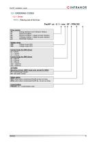
1.3 - ORDERING CODES 1.3.1 - Drives 1.3.1.1 - Ordering code of the drives PacHP- xx - U / I - mm - SF - PPACXX Drive version ak: Analog interfaces and CANopen fieldbus et: EtherCAT fieldbus ed: EtherCAT fieldbus + digital encoder interface kd: CANopen fieldbus + digital encoder interface pn: PROFINET fieldbus Voltage range 230: Voltage range 230V 400: Voltage range 400V Current range for 230V drives 05 = 5Arms 11 = 11Arms 17 = 17Arms Current range for 400V drives 08 = 08Arms 20 = 20Arms 45 = 45Arms 100 = 100Arms 200 = 200Arms OPTIONS Mounting version (400V range only, except for 200A) PT: Push-through...
Open the catalog to page 10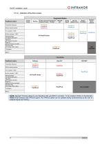
PacHP installation guide OINFRANOR
Open the catalog to page 11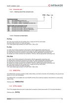
PacHP installation guide OINFRANOR 230 Connector kit for 230V drives 402 Connector kit for 400V / 08A and 20A drives X8: 5 pin plug connector for the auxiliary 24Vdc supply and for the motor brake. X9: power plug connector for mains and motor. X10: mains power plug connector for PacHP 400V / 08A to 20A X1: male 15 pin D-Sub connector for the resolver, with the appropriate conducting cover. X2: female 26 pin D-Sub HD connector for the logic I/Os, with the appropriate conducting cover. X3: male 26 pin D-Sub HD connector for the encoder, with the appropriate conducting cover. X5: female 9 pin D-Sub...
Open the catalog to page 12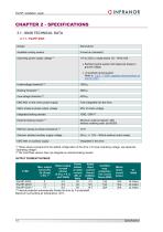
PacHP installation guide OINFRANOR (1) Internal protection automatically divides the time by 3 at standstill. Maximum surrounding air temperature: 40°C.
Open the catalog to page 13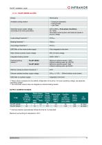
PacHP installation guide OINFRANOR Internal protection automatically divides the time by 3 at standstill. Maximum surrounding air temperature: 40°C.
Open the catalog to page 14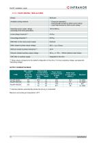
PacHP installation guide OINFRANOR Internal protection automatically divides the time by 3 at standstill. Maximum surrounding air temperature: 40°C.
Open the catalog to page 15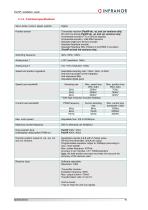
PacHP installation guide OINFRANOR
Open the catalog to page 16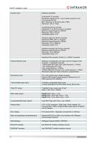
PacHP installation guide OINFRANOR
Open the catalog to page 17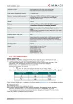
PacHP installation guide OINFRANOR PacHP installation guide OINFRANOR Automatic functions Drive adjustment to the motor (AUTOPHASING) Adjustment of the servo loops (AUTOTUNING) The file "Infranor thermal utility" is available on the Infranor website www.infranor.com for more detailed estimations. Clean the contact surface of the heatsink with alcohol. Apply a thermal interface between the drive plate and the heatsink. Recommended thermal interfaces: - A thin layer of thermal paste on the drive (recommended reference: RHODORSIL Paste 340). - Phase change thermal interface (recommended reference:...
Open the catalog to page 18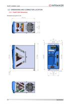
2.2 - DIMENSIONS AND CONNECTOR LOCATION 2.2.1 - PacHP 230V dimensions Dimensions are given in mm.
Open the catalog to page 19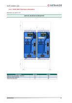
PacHP installation guide OINFRANOR VERTICAL MOUNTING IS MANDATORY
Open the catalog to page 20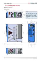
2.2.3 - PacHP 400V / 08 to 45A dimensions Dimensions are given in mm. Standard version NOTE: This bottom view is the one of the 400/45 drive (without X10 connector). The X10 connector is only available on drives with 8A and 20A current ratings.
Open the catalog to page 21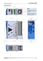
PacHP installation guide OINFRANOR Push-through version This bottom view is the one of the 400/45 drive (without X10 connector). The X10 connector is only available on drives with 8A and 20A current ratings.
Open the catalog to page 22All Infranor Group catalogs and technical brochures
 XtrapulsPac_EN
4 Pages
 SMTBSi-2Tz_en_2.1
43 Pages
 PacSimBox_d_1
1 Page
 Pac-SF01_flyer_en_18.02
4 Pages
 Pac_User_1.2.1.218
253 Pages
 Pac_Templates_en_1.9
27 Pages
 Pac_STO_Installation_en_2.2
13 Pages
 Pac_SF01_operating_en_1.6
63 Pages
 Pac_SF01_EN
4 Pages
 Pac_Installation_en_2.23
82 Pages
 Pac_flyer_en_17.12
4 Pages
 Option_CT_EMF
6 Pages
 MOVINOR_LH055_LH086_LH097_LH142
23 Pages
 ma_series
6 Pages
 GemSafeTorqueOff_en_1.1
12 Pages
 CD1pm_e_1.2(old)
18 Pages
 CD1pInst_e_7.2(old)
35 Pages
 CD1kInst_e_4.1(old)
40 Pages
 CD1k_CANopenProtocol_e_1.3(old)
86 Pages
 CD1a_e_7.1(old)
45 Pages
 Catalogue gamme SMT-BD1
11 Pages
 BM20A(F)v3_0
20 Pages
 BM20A(D)v3_0
20 Pages
 BF400(GB)v2_2
21 Pages
 BF400(D)v2_2
21 Pages
 BF230(GB)v2_0
23 Pages
 BF230(F)v2_0
23 Pages
 BD2m_e_2.2
69 Pages
 BD2m(GB)2.0
70 Pages
 BD2_e_3.2
53 Pages
 BD2(GB)3.1
53 Pages
 BD2(D)3.1
54 Pages
 Movinor_LH_e
4 Pages
 ma_series
6 Pages
 BD1t(GB)3.1
81 Pages
 BD1t(F)3.0
85 Pages
 BD1pInst(GB)3.0
25 Pages
 BD1pInst(F)3.0
23 Pages
 BD1pInst(D)3.0
24 Pages
 BD1pCD1pUse_e_2.4
57 Pages
 BD1m(GB)5.0
58 Pages
 BD1m(F)5.0
57 Pages
 BD1m(D)v3_3
64 Pages
 BD1k(GB)2.1
35 Pages
 BD1k(F)2.1
36 Pages
 BD1j(GB)v2_41
19 Pages
 BD1j(F)v2_4
21 Pages
 BD1i(GB)v2_21
23 Pages
 BD1i(F)v2_2
27 Pages
 BD1h(F)3.0
65 Pages
 BD1h(D)3.0
59 Pages
 BD1g(GB)v3_0
28 Pages
 BD1g(F)v3_0
28 Pages
 BD1a400(GB)v2_3
43 Pages
 BD1a400(F)v2_3
44 Pages
 BD1a400(D)v2_3
45 Pages
 BD1(GB)7.1_noPW
45 Pages
 BD1(GB)7.1
45 Pages
 BD1(F)7.1_noPW
47 Pages
 BD1(F)7.1
47 Pages
 BD1(D)7.1
45 Pages
 BD1 Katalog
11 Pages
 Easy_User_5.0.1.60.2
190 Pages
 01ma_smv_e_01953
40 Pages
 PacHP-SF_Flyer_en_23.06
4 Pages
 IRD_User_Manual_en_1.2.XX.54.rev_b
216 Pages
 PacHP_User_en_1.2.8.100.b
280 Pages
 PacHP_SF02_operating_en_1.6
103 Pages
 PacHP_SF01_operating_en_2.0
63 Pages
 PacHP_Series_Brochure
8 Pages
 PacHP_Flyer_us_20.10
4 Pages
 IRD_Installation_en_1.5
42 Pages
 Easy_STO_en_1.4
14 Pages
 Easy_DB_STO_en_1.2
14 Pages
 Easy_DB_Installation_en_1.4
36 Pages
 CD1pmUser_en_4.2
55 Pages
 CD1pmInst_en_8.15
40 Pages
 CD1k_CANopenProtocol_en_2.10.1.1
108 Pages
 CD1pm_ProfibusProtocol_en_1.5
50 Pages
 CD1kUser_en_2.3
26 Pages
 CD1a_en_8.17
62 Pages
 CD1kInst_en_5.16
46 Pages
 CD1_STO_en_1.8
16 Pages
 CD1_flyer_en_14.09
4 Pages
 Braking_Resistors_en_1.5
10 Pages
 XtracontrolDC2_EN
4 Pages
 Flyer_VisiTouchCNC_EN_V1.1-1
2 Pages
 XtraforsWashdown_EN-2024
2 Pages
 DataSheet_CybIO_CNC_V1.0
6 Pages
 XtraforsPrime_EN-2024
2 Pages
 XtraforsMSS_EN
4 Pages
 XtraforsMSA_EN_2024
2 Pages
 XtraforsEx_EN-2024
2 Pages
 XtraforsBR_EN-2024
2 Pages
 XtraforsBL_EN-2024
2 Pages
 XtraforsBC-ed01-vs3
4 Pages
 Manual_XtraforsPrime
46 Pages
 Drawing_1
1 Page
 Datasheet_MSS
5 Pages
 Datasheet_2
2 Pages
 Datasheet_1
4 Pages
 BLSBLT_series
2 Pages
 BL220221
2 Pages
 BL270
BL2702 Pages
 BL190
BL1902 Pages
 bl100_series
6 Pages
 bl40_series
6 Pages
 BL30
BL302 Pages
 2019-01_XtraforsFP-DSL_FR
4 Pages
 Movinor_T_EN
4 Pages
 Movinor_N_EN
4 Pages
 Movinor_Low_Voltage_EN
4 Pages
 Manual Movinor T 03-2026
46 Pages
 Manual Movinor N 03-2026
63 Pages
 XtrapulsEasy™ AC servo-drive
4 Pages
 XtrapulsCD1 AC servo-drives
4 Pages
 CybIO
CybIO6 Pages
 AC SERVOMOTORS
2 Pages
 Movinor® N AC Servomotors
4 Pages






Archived catalogs
 AN_CD1ak_AbsoluteEncoder_en_2.0
10 Pages
 AN_CD1ak_SinCosTracks_e_1.0
7 Pages
 AN_CD1pm_AbsoluteEncoder_en_2.0
10 Pages
 AN_CD1pm_SinCosTracks_e_1.0
7 Pages
 AN_DC_bus_interfacing_en_1.3
5 Pages
 CD1_EC_conformity_24.05
1 Page
 CD1_STO_conformity_19.02
2 Pages
 EtherCAT Interface_en_1.3
20 Pages
 Easy_EC_Conformity_24_10
1 Page
 GDPS_EC_conformity_24.07
1 Page
 IRD_EC_Conformity_25.03
1 Page
 PacHP_TÜV_certificate_25.07
2 Pages
 BD1c(F)v2_01
19 Pages
 BD1c(GB)v2_01
19 Pages
 BD1d(F)v2_01
25 Pages
 BD1d(GB)v2_01
25 Pages
 BD1e(F)v2_01
22 Pages
 BD1f(F)v2_01
17 Pages
 BD1f(GB)v2_01
18 Pages
 Pac_EC_conformity_25.04
1 Page




















