
- Catalogs
- Infranor Group
- Pac_User_1.2.1.218


Pac_User_1.2.1.218

Pac_User_1.2.1.218
The document is a comprehensive user guide for the XtrapulsPac™ series of servo drives, designed for AC brushless sinusoidal servo motors. It emphasizes the importance of reading the manual thoroughly to ensure proper handling and compliance with standards.
Users are warned about electrical contact risks and advised to wait at least 10 minutes after power down before handling the drives. Electrostatic discharge (ESD) precautions are outlined to prevent damage to sensitive components.
The guide details the classification of INFRANOR® products under WEEE regulations, emphasizing selective disposal and recycling. Specific instructions for waste management of components like packaging, documents, and electronic boards are provided.
This section covers the installation of PC software, starting the software, and establishing drive communication. It includes steps for parameter setting, drive and motor configuration, and servo loop adjustment. A quick test procedure for the servo drive is also provided.
The guide includes a comprehensive reference section on CANopen communication, detailing communication objects, network initialization, and device profiles. It explains the drive state machine, error and warning management, and drive parameters.
Users are directed to additional documents for specific functions and installations, such as the XtrapulsPac™ Installation Guide, STO function, and EtherCAT® fieldbus interface manual.
The XtrapulsPac™ drive is configurable with parameters for servo-loop, motor, sensor, communication, and I/O configurations. It supports multiple modes including Profile Torque, Profile Velocity, Profile Position, and Homing.
The document details various operation modes such as Profile Position Mode, Homing Mode, and Interpolated Position Mode, each with specific functionalities and configurations.
These functions include Master-Slave, Virtual Master, and Gearbox Function, allowing for synchronized operations and advanced control strategies.
Maintenance procedures cover file management and firmware updates to ensure efficient operation and up-to-date functionality.
The software consists of independent modules that communicate with the drives via a communication server, supporting various communication types for efficient data exchange.
Drive parameters are defined by an Index, Sub-index, and properties such as Save type, Data type, Unit, Min/Max value, and Default value, stored in an XML file called EEDS.
Communication with the drives is established via RS232 or CANopen, with unique node ID codes set for each drive.
Configuration involves selecting the target application in the Device Config window, with Expert mode allowing access to full parameter sets.
Motor configuration can be done by selecting from the motor catalog or manually entering parameters if not listed.
Enable and configure encoder inputs based on the type, adjusting parameters as needed.
Adjust current limits and loop settings, with parameters like Maximum current and Rated current being critical for operation.
Select the sensor type and adjust the triggering threshold for over-temperature protection.
Configured in degrees Celsius, with sensor's ohmic value set to correspond to a warning temperature.
Two modes are available: Fusing and Limiting, with Fusing mode recommended during commissioning.
The Maximum speed parameter defines the motor's speed limit, with a recommended margin for the speed set point.
This procedure identifies motor parameters such as Pole pairs, Phase order, and Position sensor offset.
Encoder resolution and Maximum speed parameters are calculated using specific formulas.
The drive supports various position sensor types, with internal position and speed setpoints defined using the “user unit” definition.
The Auto-tuning procedure calculates speed and position loop gain values, with adjustments made based on application requirements.
Speed loop gains depend on mechanical load characteristics, with parameters like Proportional speed gain and Integral speed gain being critical.
The document outlines procedures for configuring and testing a servo drive system, focusing on error thresholds and tuning parameters.
Speed and position error thresholds are critical for drive protection, with recommended settings provided.
Stability is tested in both velocity and position modes, with adjustments recommended for noise issues.
Parameters such as maximum velocity, acceleration, and deceleration are set according to motor speed and mechanical load limitations.
Details various logic inputs and outputs for controlling the drive, including ENABLE, INHIBIT, and LIMIT SWITCH.
Covers the setup of external I/Os modules and the operation of braking resistors.
Outlines the configuration of the drive when connected to an XtrapulsGDPS™ power supply, with specific modes for braking resistor operation.
Parameters can be stored in non-volatile memory, with options for backup and restoration.
The oscilloscope in Gem Drive Studio software allows signal display, and the dialog terminal allows reading and writing parameter values.
Provides definitions and conventions related to CAN communication, including terms like COB, NMT, PDO, and SDO.
Details communication objects, including CAN telegrams, network management objects, and process data objects (PDOs).
Defines communication parameter objects for each Receive PDO (RPDO), including COB-ID and transmission type.
Defines the number of mapped objects and their default values for each RPDO.
Transmit PDOs (TPDOs) have communication parameter objects with default COB-ID values.
Defines the number of mapped objects and their default values for each TPDO.
Controls the number of cyclic TPDOs for each axis, requiring synchronization with the SYNC message.
Facilitate a client/server communication model, allowing access to the server's object dictionary.
Emergency messages are sent based on the EMCY message behavior object.
Involves guard time and life time factor objects to define the life time for the protocol.
The NMT state machine manages communication states, with specific objects defining reset behaviors and bootup configurations.
Provides a detailed description of the drive state machine for the XtrapulsPac™ device.
Describes the status and control sequence of the drive, with possible states and transitions.
Triggered by internal events or host commands via the control word.
Used to manage and monitor the drive's state, allowing for various commands.
Provides additional functionalities such as soft-start activation and motor speed detection.
Errors are managed through specific objects, with emergency messages sent with the last error code.
This document serves as a comprehensive guide for understanding the operational states, control mechanisms, and error handling procedures for the XtrapulsPac™ device.
Drive parameters allow selecting a Stop behavior for specific drive faults, with careful analysis required for compatibility.
Stop 3 requires fully operating motor power control and uncorrupted motor position feedback.
Most faults are not compatible with Stop 2 or Stop 3, with a detailed chart listing possible stop selections.
Warnings are displayed and automatically clear when resolved, with a list of warning codes provided.
Detailed with parameters for mode and signal, including a formula for calculating RMS motor current.
Parameters for protecting the braking resistor against overheating are described.
Descriptions of Stop 1, Stop 2, and Stop 3 operations are provided, including their respective stop codes and actions.
Defines the behavior of the system when a SHUTDOWN command is executed.
Outlines the behavior when a DISABLE_OPERATION command is executed.
Describes the stop behavior when an Inhibit logic input is activated.
Parameters for slow down deceleration are defined.
Defines the deceleration for a quick stop with specific option codes.
Defines the current limit when a stop on current limit is performed.
Defines the time limit for stop operations.
Includes motor parameters such as number of pole pairs, motor phase, and motor offset.
Details the timing and control of the motor brake.
Defines parameters for motor current limitations and the calculation of current loop gains.
Provides information on the peak and rated current supported by the power module.
Defines the undervoltage error level for different drive voltages.
Allows for the calculation of current loop parameters when motor inductance and drive current are correct.
Calculates current limit values.
Defines the maximum and rated current the drive can supply to the motor.
Defines the parameters of the current loops, including proportional and integral gains.
Allows adding an offset to the current command.
Provides the actual DC current value in the drive.
Sets the undervoltage warning level on the DC bus.
Manage dynamic current limits, allowing for real-time adjustments.
Configures and monitors motor temperature using different types of probes.
Provides temperature information for the IGBT module.
The Xtrapuls servo drive supports two sensor inputs for motor and position feedback.
Covers resolver monitoring, setup, error control, and position monitoring.
The document provides detailed technical specifications and setup instructions for various types of encoders used with XtrapulsPac™ drives.
Lists parameters for Encoder 1 and Encoder 2, including types, configurations, error controls, calibration, and position monitoring.
Involves configuring encoder types and parameters.
Describes different encoder types and their applications.
Explains how encoder positions are monitored and adjusted using position offsets.
Supports digital interfaces and requires specific setup for protocols like Hiperface DSL® and EnDAT®.
The document serves as a comprehensive guide for setting up and configuring encoders with XtrapulsPac™ drives.
Defines resolution, factor, and maximum revolution for encoders.
An absolute encoder provides the motor's absolute position value over one revolution.
Adjustments can be made using specific objects to ensure correct operation.
Set the encoder zero position outside the axis range using software procedures.
Defines position, velocity, and acceleration units.
Involves various gains and filters to optimize performance.
Outlines various operation modes for a drive system.
Uses a trapezoidal trajectory generator to execute positioning.
Defines various parameters such as Target Position and Max Motor Speed.
Used to set the motor to a known position when the feedback sensor does not provide an absolute position.
Describes various homing methods with specific search criteria.
Involves searching for the home switch in a positive direction at a specified speed.
Specifies motor speeds during homing.
Defines the acceleration during homing.
Sets the current limit during homing.
Determines if the drive moves to the home position after homing.
Indicates the status of the homing operation.
Coordinates multiple axes with synchronized cycle times.
Allows operation with a velocity reference.
Operates with current loops only.
Enables pre-programmed sequences for basic moves.
Sequences are controlled using the Control Word and Status Word.
Managed by parameters such as SeqNext, SeqCount, SeqLink, and StartCond.
Loading a sequence file erases all sequence parameters in memory.
Various objects allow control over sequence execution.
Main parameters include position, motion speed, acceleration, deceleration, and delay time.
Parameters include Home Offset, Home method, speeds, acceleration, and current limit.
Involves speed setpoint, acceleration, deceleration, and running time.
Focuses on speed setpoint, acceleration, running time, and current limit.
Includes parameters for gearing behavior, ratio factor, acceleration, and synchronization distances.
Controlled by SeqCount, SeqNext, SeqLink, and StartCond.
Provides a detailed guide on the sequence programming and parameters for the XtrapulsPac™ system.
Describes two scenarios for sequence execution based on the activation of logic input 8.
Key parameters include SeqNb, SeqType, NextSeq, SeqCount, SeqLink, and Trigger.
Details the configuration of sequence inputs and outputs.
Sequence files are text-based and not case-sensitive.
Supports various sequence types, including positioning, homing, speed, torque, and gear sequences.
Apply to all sequence types and include sequence type, next sequence, sequence counter, conditional jump, output, and trigger.
Outlines the positioning sequence for a system.
Describes the homing sequence.
Involves move speed, acceleration time, deceleration time, and move time.
Mimics a stepper motor's behavior using PULSE and DIR inputs.
In analog speed mode, the drive operates as a variable speed drive.
Supports gearbox functions with specific control and status word bits.
Describes the master-slave relationship where several drives run as slaves following a master.
Outlines the master-slave functions supported by different device models.
Provides a detailed list of master-slave objects.
Explains how to connect a 32-bit dataflow as a master input signal.
Details on how to add an offset signal to the master signal.
Describes the control and status objects for master-slave functions.
Definitions are provided for slave parameters such as acceleration, differential speed, phase shift distance, jog speed, and offset signal.
Generates a position signal with a defined profile.
Synchronizes slave movement with a master signal based on a defined ratio.
Outlines the synchronization and gearbox functionalities for a slave device.
Allows for phase adjustments of the slave relative to the master.
The gearbox can operate in frequency synchronization or both frequency and phase synchronization.
Several objects are defined for managing gearbox functions.
The Xtrapuls drive allows configuration of digital inputs and outputs.
The Xtrapuls servo drives include two analog inputs, which can be used for functions such as speed reference.
Outlines the specifications for the XtrapulsPac™ drive, focusing on its analog and digital input/output capabilities.
Sub-indexes detail the configuration of analog inputs and outputs.
The drive supports encoder emulation, allowing it to mimic an incremental encoder output.
The digital cam functionality is defined by specific objects.
The capture function is designed to latch a data signal on a trigger input signal.
Provides detailed object definitions for configuring and accessing various features of the XtrapulsPac™ drive.
Defines a logic input as a capture trigger signal.
Allows enabling and configuring touch probes with various trigger sources.
Stores positive and negative position values for two touch probes.
Defines the source for touch probes.
Configures the modulo function to limit motor position within specified limits.
Sets minimum and maximum position limits.
The XtrapulsPac™-ak servo drive supports an external CANopen I/O module.
Manages the assignment of digital inputs and outputs to drive variables.
Handles the assignment of analog inputs and outputs.
Outlines communication parameters for the CANopen I/O module.
This document is a technical reference guide for the XtrapulsPac™ system.
Defines control parameters for CANopen I/O modules.
Includes file management and firmware update procedures.
Provides a comprehensive list of parameters and their descriptions.
Includes data types, PDO mapping, and firmware update commands.
Includes configuration and maintenance recommendations.
Encoder 2 settings include parameters for virtual top Z shift and size, offset, position, velocity, and raw position.
Includes current loop monitoring, DC voltage monitoring, and dynamic current limit configuration.
Includes Profile Position Mode, Homing Mode, Interpolated Position Mode, and Profile Velocity Mode.
Covers sequence inputs, outputs, configuration, and parameters.
Details on digital inputs/outputs configuration, polarity, and user inputs/outputs.
Includes encoder emulation output, digital cam positions, oscilloscope functions, and firmware update procedures.
Infranor Group provides motion solutions with a global presence, offering engineering skills and high-quality products.
Catalog excerpts
DIGITAL SERVO DRIVES FOR BRUSHLESS AC MOTORS XtrapulsPac™ – User Guide
Open the catalog to page 1
XtrapulsPac™ – User Guide ! This is a general manual describing a series of servo drives having output capability suitable for driving AC brushless sinusoidal servo motors. Please see also: o XtrapulsPac™ Installation Guide for the hardware installation of the drive (mounting, wiring, …). o XtrapulsPac™ STO for the Safe Torque Off function o XtrapulsPac™ Templates for the templates of target applications. o Gem Drive Studio software Quick Start manual for the drive parameterization. o EtherCAT® fieldbus interface manual for the XtrapulsPac-et version. o XtrapulsGDPS™ manual, for the use of the...
Open the catalog to page 2
XtrapulsPac™ – User Guide All electrical industrial automatisms which lifetime is coming to its end are Waste Electronic and Electrical Equipment (WEEE) according to article R543-172 of the French Environmental Code. WEEE classification of the INFRANOR products Categorie 9: Monitoring and control instruments In accordance with the Decree nr. 2012-617 of May 2nd, 2012 which specifies the provisions related to the professional EEE manufacturers' obligations, INFRANOR France is a member of RECYLUM : ecoorganization ecosystem certified for the collection, treatment and recycling of WEEE. In France,...
Open the catalog to page 3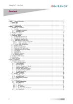
XtrapulsPac™ – User Guide
Open the catalog to page 4
XtrapulsPac™ - User Guide
Open the catalog to page 5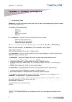
XtrapulsPac™ - User Guide CINFRANOFT 1.1 - INTRODUCTION XtrapulsPac™ all-digital drives with sinusoidal PWM control are servo drives that provide the control of brushless AC motors with position sensor. The standard control inferface can be: - stepper motor emulation, But the XtrapulsPac™ range also offers more sophisticated functions such as: - DS402 including position capture, - Master/slave and electronic gearing, - Positioner with motion sequencing. All versions are delivered as standard with the integrated protection function Safe Torque Off : STO SIL 2. With its very small dimensions, the...
Open the catalog to page 6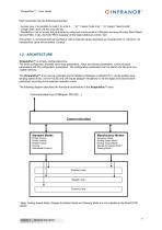
XtrapulsPac™ – User Guide Each parameter has the following properties: - Access type: it is possible to read it, to write it….; "ro" ” means "read only" , “rw“ means "read & write". - Length: byte, word (16 bit), long (32 bit). - Possibility or not to access the parameter by using fast communication CANopen services (Process Data Object service PDO). If yes, the field “PDO mapping” of the object dictionary will be “yes”. Convention: A numerical field can be filled-in with numerical values described as “hexadecimal” or “decimal”. An hexadecimal value will be written “0xvalue”. 1.2 - ARCHITECTURE...
Open the catalog to page 7
XtrapulsPac™ - User Guide CINFRANOFT1.3 - OTHER DOCUMENTS • XtrapulsPac™ Installation guide. • XtrapulsPac™ "Safe Torque Off' specification. • XtrapulsPac™ Templates. • Gem Drive Studio Quick Start guide • EtherCAT® fieldbus interface. • XtrapulsGDPS™ manual, for the use of the GDPS power supply unit Chapter 1 - General description
Open the catalog to page 8
XtrapulsPac™ - User Guide CINFRANOFTChapter 2 - Commissioi This chapter describes the commissioning procedure of the drive by means of the "Gem Drive Studio" software. Do not perform the drive parameterization by means of both "Gem Drive Studio" software tool and CANopen® bus at the same time. The Gem Drive Studio software is PC compliant under Windows® and allows an easy parameterization of the Xtrapuls drive. Please see our website www.infranor.com for downloading the “Gem Drive Studio” software. Minimum Configuration The use of the Gem Drive Studio software requires the minimum PC configuration...
Open the catalog to page 9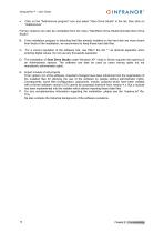
XtrapulsPac™ – User Guide Click on the "Add/remove program" icon and select "Gem Drive Studio" in the list, then click on "Add/remove". Former versions can also be uninstalled from the menu "Start/Gem Drive Studio/Uninstall Gem Drive Studio". B. If the installation program is detecting that files already installed on the hard disk are more recent than those of the installation, we recommend to keep these hard disk files. C. For a correct operation of the software tool, use ONLY the dot "." as decimal separator when entering digital values. Do not use any thousands separator. D. The installation...
Open the catalog to page 10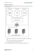
XtrapulsPac™ – User Guide Architecture of the software The software is made of several independent software modules. Each of them can communicate with the drive(s) via a communication server. Client module Client module Client module Communication server Serial port or CAN port The server is automatically started when a client module is trying to establish a communication with a drive. The server is commissioning the drivers of the hardware peripherals. The server stops when the last connected client is stopped. The format of the exchanged data is the same whichever the communication type (RS232,...
Open the catalog to page 11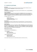
XtrapulsPac™ - User Guide CINFRANOFT2.2 - STARTING THE SOFTWAREUser levels When starting the software, various user levels can be selected. The drive parameter modification levels are protected by passwords. Administrator is the highest level with full access. The Administrator can change all passwords by using the Tools/User identification menu. The default password for the administrator level is "admin". The Gem Drive Studio software allows the parameterization of all Xtrapuls drives for a given application. All Xtrapuls drives of a given application, connected together via CANopen, are included...
Open the catalog to page 12
XtrapulsPac™ – User Guide 2.3 - DRIVE COMMUNICATION Powering the drives Please see manual "Installation Guide" before switching on the drives for the first time. For switching on the drives, proceed as follows: - Switch on the +24 V auxiliary supply: The red front panel LED "ERR" must be blinking ("Undervolt" error displayed). The AOK relay contact is closed. It is then possible to control the Power ON relay. - Switch on the power supply: The red ERR LED must be unlit. The drive is ready to be enabled. Starting the communication The Gem Drive Studio software can communicate with the drives by...
Open the catalog to page 13All Infranor Group catalogs and technical brochures
 XtrapulsPac_EN
4 Pages
 SMTBSi-2Tz_en_2.1
43 Pages
 PacSimBox_d_1
1 Page
 Pac-SF01_flyer_en_18.02
4 Pages
 Pac_Templates_en_1.9
27 Pages
 Pac_STO_Installation_en_2.2
13 Pages
 Pac_SF01_operating_en_1.6
63 Pages
 Pac_SF01_EN
4 Pages
 Pac_Installation_en_2.23
82 Pages
 Pac_flyer_en_17.12
4 Pages
 Option_CT_EMF
6 Pages
 MOVINOR_LH055_LH086_LH097_LH142
23 Pages
 ma_series
6 Pages
 GemSafeTorqueOff_en_1.1
12 Pages
 CD1pm_e_1.2(old)
18 Pages
 CD1pInst_e_7.2(old)
35 Pages
 CD1kInst_e_4.1(old)
40 Pages
 CD1k_CANopenProtocol_e_1.3(old)
86 Pages
 CD1a_e_7.1(old)
45 Pages
 Catalogue gamme SMT-BD1
11 Pages
 BM20A(F)v3_0
20 Pages
 BM20A(D)v3_0
20 Pages
 BF400(GB)v2_2
21 Pages
 BF400(D)v2_2
21 Pages
 BF230(GB)v2_0
23 Pages
 BF230(F)v2_0
23 Pages
 BD2m_e_2.2
69 Pages
 BD2m(GB)2.0
70 Pages
 BD2_e_3.2
53 Pages
 BD2(GB)3.1
53 Pages
 BD2(D)3.1
54 Pages
 Movinor_LH_e
4 Pages
 ma_series
6 Pages
 BD1t(GB)3.1
81 Pages
 BD1t(F)3.0
85 Pages
 BD1pInst(GB)3.0
25 Pages
 BD1pInst(F)3.0
23 Pages
 BD1pInst(D)3.0
24 Pages
 BD1pCD1pUse_e_2.4
57 Pages
 BD1m(GB)5.0
58 Pages
 BD1m(F)5.0
57 Pages
 BD1m(D)v3_3
64 Pages
 BD1k(GB)2.1
35 Pages
 BD1k(F)2.1
36 Pages
 BD1j(GB)v2_41
19 Pages
 BD1j(F)v2_4
21 Pages
 BD1i(GB)v2_21
23 Pages
 BD1i(F)v2_2
27 Pages
 BD1h(F)3.0
65 Pages
 BD1h(D)3.0
59 Pages
 BD1g(GB)v3_0
28 Pages
 BD1g(F)v3_0
28 Pages
 BD1a400(GB)v2_3
43 Pages
 BD1a400(F)v2_3
44 Pages
 BD1a400(D)v2_3
45 Pages
 BD1(GB)7.1_noPW
45 Pages
 BD1(GB)7.1
45 Pages
 BD1(F)7.1_noPW
47 Pages
 BD1(F)7.1
47 Pages
 BD1(D)7.1
45 Pages
 BD1 Katalog
11 Pages
 Easy_User_5.0.1.60.2
190 Pages
 01ma_smv_e_01953
40 Pages
 PacHP-SF_Flyer_en_23.06
4 Pages
 IRD_User_Manual_en_1.2.XX.54.rev_b
216 Pages
 PacHP_User_en_1.2.8.100.b
280 Pages
 PacHP_SF02_operating_en_1.6
103 Pages
 PacHP_SF01_operating_en_2.0
63 Pages
 PacHP_Installation_en_2.9
91 Pages
 PacHP_Series_Brochure
8 Pages
 PacHP_Flyer_us_20.10
4 Pages
 IRD_Installation_en_1.5
42 Pages
 Easy_STO_en_1.4
14 Pages
 Easy_DB_STO_en_1.2
14 Pages
 Easy_DB_Installation_en_1.4
36 Pages
 CD1pmUser_en_4.2
55 Pages
 CD1pmInst_en_8.15
40 Pages
 CD1k_CANopenProtocol_en_2.10.1.1
108 Pages
 CD1pm_ProfibusProtocol_en_1.5
50 Pages
 CD1kUser_en_2.3
26 Pages
 CD1a_en_8.17
62 Pages
 CD1kInst_en_5.16
46 Pages
 CD1_STO_en_1.8
16 Pages
 CD1_flyer_en_14.09
4 Pages
 Braking_Resistors_en_1.5
10 Pages
 XtracontrolDC2_EN
4 Pages
 Flyer_VisiTouchCNC_EN_V1.1-1
2 Pages
 XtraforsWashdown_EN-2024
2 Pages
 DataSheet_CybIO_CNC_V1.0
6 Pages
 XtraforsPrime_EN-2024
2 Pages
 XtraforsMSS_EN
4 Pages
 XtraforsMSA_EN_2024
2 Pages
 XtraforsEx_EN-2024
2 Pages
 XtraforsBR_EN-2024
2 Pages
 XtraforsBL_EN-2024
2 Pages
 XtraforsBC-ed01-vs3
4 Pages
 Manual_XtraforsPrime
46 Pages
 Drawing_1
1 Page
 Datasheet_MSS
5 Pages
 Datasheet_2
2 Pages
 Datasheet_1
4 Pages
 BLSBLT_series
2 Pages
 BL220221
2 Pages
 BL270
BL2702 Pages
 BL190
BL1902 Pages
 bl100_series
6 Pages
 bl40_series
6 Pages
 BL30
BL302 Pages
 2019-01_XtraforsFP-DSL_FR
4 Pages
 Movinor_T_EN
4 Pages
 Movinor_N_EN
4 Pages
 Movinor_Low_Voltage_EN
4 Pages
 Manual Movinor T 03-2026
46 Pages
 Manual Movinor N 03-2026
63 Pages
 XtrapulsEasy™ AC servo-drive
4 Pages
 XtrapulsCD1 AC servo-drives
4 Pages
 CybIO
CybIO6 Pages
 AC SERVOMOTORS
2 Pages
 Movinor® N AC Servomotors
4 Pages






Archived catalogs
 AN_CD1ak_AbsoluteEncoder_en_2.0
10 Pages
 AN_CD1ak_SinCosTracks_e_1.0
7 Pages
 AN_CD1pm_AbsoluteEncoder_en_2.0
10 Pages
 AN_CD1pm_SinCosTracks_e_1.0
7 Pages
 AN_DC_bus_interfacing_en_1.3
5 Pages
 CD1_EC_conformity_24.05
1 Page
 CD1_STO_conformity_19.02
2 Pages
 EtherCAT Interface_en_1.3
20 Pages
 Easy_EC_Conformity_24_10
1 Page
 GDPS_EC_conformity_24.07
1 Page
 IRD_EC_Conformity_25.03
1 Page
 PacHP_TÜV_certificate_25.07
2 Pages
 BD1c(F)v2_01
19 Pages
 BD1c(GB)v2_01
19 Pages
 BD1d(F)v2_01
25 Pages
 BD1d(GB)v2_01
25 Pages
 BD1e(F)v2_01
22 Pages
 BD1f(F)v2_01
17 Pages
 BD1f(GB)v2_01
18 Pages
 Pac_EC_conformity_25.04
1 Page




















