
- Catalogs
- Infranor Group
- Pac_Templates_en_1.9


Pac_Templates_en_1.9

Pac_Templates_en_1.9
XtrapulsPac™ digital servo drives are designed for controlling brushless AC motors using sinusoidal PWM control. They support interfaces like CANopen, EtherCAT, analog, stepper motor emulation, and logic I/Os. Features include DS402, master/slave configurations, motion sequencing, and integrated Safe Torque Off (STO) protection. Available in stand-alone or multi-axis versions with various cooling options.
Installation must follow the manual to ensure compliance with standards and CE approval. Maintenance should be performed by technicians familiar with EN 60204-1 standards. Drives are protected against electrostatic discharges but require careful handling and storage.
INFRANOR devices are classified as WEEE and must be disposed of according to regulations. In France, INFRANOR is part of the RECYLUM eco-organization for WEEE recycling.
Templates for configuring XtrapulsPac™ drives using Gem Drive Studio software include:
- Basic and Advanced Analog Speed Drive
- Basic and Advanced Stand-Alone Positioner
- Basic and Advanced Stepper Motor Emulation
Uses an analog voltage input (±10 V) for motor speed control, with encoder emulation output for rotor position monitoring. Includes inputs for enabling/disabling the drive, adjusting acceleration/deceleration, and controlling motor rotation with limit switches and a STOP input. Outputs manage motor brake and drive status.
Involves setting motor parameters, user position scaling, analog command scaling, and encoder output parameters using Gem Drive Studio software.
Description: Uses an analog voltage input (±10 V) to control motor speed, with encoder emulation output for rotor position monitoring. Suitable for conventional DNC control.
Configuration: Involves establishing communication with the drive, selecting the template, and connecting the ANA1 input.
Commissioning: Includes setting motor parameters, configuring analog command scaling, and using Auto-tuning for servo loop gains.
Description: Allows programming up to 32 control sequences for applications like axis homing and speed profile running.
Configuration: Involves establishing communication with the drive and selecting the template.
Commissioning: Includes setting motor parameters, configuring manual movement parameters, and using Auto-tuning for servo loop gains.
Description: Supports up to 32 control sequences for complex applications with sequence chaining capabilities.
Configuration: Similar to the basic template with additional setup for sequence chaining.
Commissioning: Involves similar steps as the basic template with additional configuration for sequence chaining.
Uses PULSE and DIR logic inputs to command motor position. Programmable steps per revolution range from 10 to 100,000. Requires a motor with a resolver for position feedback.
Involves starting the software, establishing communication, selecting the template, and setting motor parameters.
Similar to the basic configuration with additional features like configurable logic inputs and outputs.
Similar to the basic template with additional setup for logic I/Os.
Infranor Group provides customized motion solutions with a global presence in countries like the USA, UK, and China.
Catalog excerpts
OINFRANOR XtrapulsPac™ Application Templates
Open the catalog to page 1
XtrapulsPac™ – Application templates ! This is a general manual describing a series of servo drives having output capability suitable for driving AC brushless sinusoidal servo motors. Please see also: o XtrapulsPac™ Installation Guide for the hardware installation of the drive (mounting, wiring, ...) o XtrapulsPac™ STO for the Safe Torque Off function o XtrapulsPac™ User Guide for the operation of the drive (commissioning, configuration, ...) o Gem Drive Studio software Quick Start manual for the drive parameterization. Instructions for storage, use after storage, commissioning as well as all...
Open the catalog to page 2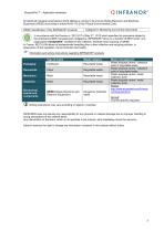
XtrapulsPac™ - Application templates All electrical industrial automatisms which lifetime is coming to its end are Waste Electronic and Electrical Equipment (WEEE) according to article R543-172 of the French Environmental Code. WEEE classification of the INFRANOR® products Categorie 9: Monitoring and control instruments In accordance with the Decree nr. 2012-617 of May 2nd, 2012 which specifies the provisions related to the professional EEE manufacturers' obligations, INFRANOR France is a member of RECYLUM : ecoorganization ecosystem® certified for the collection, treatment and recycling of WEEE....
Open the catalog to page 3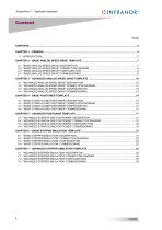
XtrapulsPac™ – Application templates
Open the catalog to page 4
XtrapulsPac™ - Application templates XtrapulsPac™ all-digital drives with sinusoidal PWM control are servo drives that provide the control of brushless AC motors with a position sensor. The standard control interface can be: - stepper motor emulation, But the XtrapulsPac™ range also offers more sophisticated functions such as: - DS402 including position capture, - Master/slave and electronic gearing, - Positioner with motion sequencing. All versions are delivered as standard with the integrated protection function Safe Torque Off : STO SIL 2. With its very small dimensions, the XtrapulsPac™ is...
Open the catalog to page 5
XtrapulsPac™ - Application templates The application templates described in this document are listed below: - Basic analog speed drive, - Basic stand alone positioner, - Basic stepper motor emulation, - Advanced analog speed drive, - Advanced stand-alone positioner, - Advanced stepper motor emulation.
Open the catalog to page 6
XtrapulsPac™ – Application templates Chapter 2 – Basic analog speed drive template 2.1 - "BASIC ANALOG SPEED DRIVE" DESCRIPTION When the XtrapulsPac™ drive is configured with the Basic Analog Speed Drive template, the motor speed input command is an analog voltage (± 10 V), and the rotor position monitor is available as two channels A and B in quadrature and one marker pulse per revolution (encoder emulation output). The maximum motor speed according to a 10 V input voltage is programmable from 100 rpm to 25'000 rpm. The encoder emulation output resolution is also programmable. All values (binary...
Open the catalog to page 7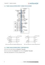
XtrapulsPac™ - Application templates 2.2 - "BASIC ANALOG SPEED DRIVE" CONNECTION DIAGRAM XtrapulsPac Polarity must be observed: 50V max. IN3 = STOP IN4 = ENABLE IN5 = RESET Differential analog input +/-10V 7Y~7r Differential encoder outputs RS422 5V/20mA max. ANA 2 = lliml Direct analog GND J input +/-10V ANA1 input connection with a differential analog signal source 2.3 - "BASIC ANALOG SPEED DRIVE" CONFIGURATIONStart the Gem Drive Studio software (see XtrapulsPac™ User guide).Start the communication with the XtrapulsPac™ servo drive (see XtrapulsPac™ User guide) Select "Basic Analog Speed Drive"...
Open the catalog to page 8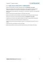
XtrapulsPac™ – Application templates 2.4 - "BASIC ANALOG SPEED DRIVE" COMMISSIONING Setup the motor parameters in the Motor Configuration window (see XtrapulsPac™ User guide) Setup the user position scaling, in the Position sensors window, in order to get the axis position and speed displayed in the application unit according to the mechanical load (not mandatory for a speed drive). Setup the analog command scaling (max. motor speed for 10 V) and the accel / decel ramp in the Analog Speed Ref window. Setup the encoder output parameters (resolution) in the Encoder Output window. Setup the Stop...
Open the catalog to page 9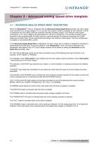
XtrapulsPac™ – Application templates Chapter 3 – Advanced analog speed drive template 3.1 - "ADVANCED ANALOG SPEED DRIVE" DESCRIPTION When the XtrapulsPac™ drive is configured with the Advanced Analog Speed Drive template, the motor speed input command is an analog voltage (± 10 V), and the rotor position monitor is available as two channels A and B in quadrature and one marker pulse per revolution (encoder emulation output). The maximum motor speed according to a 10 V input voltage is programmable from 100 rpm to 25'000 rpm. The encoder emulation output resolution is also programmable. All values...
Open the catalog to page 10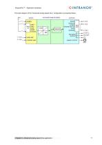
XtrapulsPac™ – Application templates The block diagram of the “Advanced analog speed drive” configuration is presented below. Chapter 3 – Advanced analog speed drive applicat
Open the catalog to page 11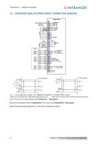
XtrapulsPac™ – Application templates 3.2 - "ADVANCED ANALOG SPEED DRIVE" CONNECTION DIAGRAM 3.3 - "ADVANCED ANALOG SPEED DRIVE" CONFIGURATION ANA1 input connection with a differential analog signal source ANA1 input connection with a unipolar analog signal source Start the Gem Drive Studio software (see XtrapulsPac™ User guide). Start the communication with the XtrapulsPac™ servo drive (see XtrapulsPac™ User guide) Select "Advanced Analog Speed Drive" in the Drive Configuration window. Chapter 3 – Advanced analog speed drive ap
Open the catalog to page 12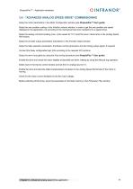
XtrapulsPac™ – Application templates 3.4 - "ADVANCED ANALOG SPEED DRIVE" COMMISSIONING Setup the motor parameters in the Motor Configuration window (see XtrapulsPac™ User guide) Setup the user position scaling, in the Position sensors window, in order to get the axis position and speed displayed in the application unit according to the mechanical load (not mandatory for a speed drive). Setup the analog command scaling (max. motor speed for 10 V) and the accel / decel ramp in the Analog Speed Ref window. Setup the encoder output parameters (resolution) in the Encoder Output window. Setup the Stop...
Open the catalog to page 13All Infranor Group catalogs and technical brochures
 XtrapulsPac_EN
4 Pages
 SMTBSi-2Tz_en_2.1
43 Pages
 PacSimBox_d_1
1 Page
 Pac-SF01_flyer_en_18.02
4 Pages
 Pac_User_1.2.1.218
253 Pages
 Pac_STO_Installation_en_2.2
13 Pages
 Pac_SF01_operating_en_1.6
63 Pages
 Pac_SF01_EN
4 Pages
 Pac_Installation_en_2.23
82 Pages
 Pac_flyer_en_17.12
4 Pages
 Option_CT_EMF
6 Pages
 MOVINOR_LH055_LH086_LH097_LH142
23 Pages
 ma_series
6 Pages
 GemSafeTorqueOff_en_1.1
12 Pages
 CD1pm_e_1.2(old)
18 Pages
 CD1pInst_e_7.2(old)
35 Pages
 CD1kInst_e_4.1(old)
40 Pages
 CD1k_CANopenProtocol_e_1.3(old)
86 Pages
 CD1a_e_7.1(old)
45 Pages
 Catalogue gamme SMT-BD1
11 Pages
 BM20A(F)v3_0
20 Pages
 BM20A(D)v3_0
20 Pages
 BF400(GB)v2_2
21 Pages
 BF400(D)v2_2
21 Pages
 BF230(GB)v2_0
23 Pages
 BF230(F)v2_0
23 Pages
 BD2m_e_2.2
69 Pages
 BD2m(GB)2.0
70 Pages
 BD2_e_3.2
53 Pages
 BD2(GB)3.1
53 Pages
 BD2(D)3.1
54 Pages
 Movinor_LH_e
4 Pages
 ma_series
6 Pages
 BD1t(GB)3.1
81 Pages
 BD1t(F)3.0
85 Pages
 BD1pInst(GB)3.0
25 Pages
 BD1pInst(F)3.0
23 Pages
 BD1pInst(D)3.0
24 Pages
 BD1pCD1pUse_e_2.4
57 Pages
 BD1m(GB)5.0
58 Pages
 BD1m(F)5.0
57 Pages
 BD1m(D)v3_3
64 Pages
 BD1k(GB)2.1
35 Pages
 BD1k(F)2.1
36 Pages
 BD1j(GB)v2_41
19 Pages
 BD1j(F)v2_4
21 Pages
 BD1i(GB)v2_21
23 Pages
 BD1i(F)v2_2
27 Pages
 BD1h(F)3.0
65 Pages
 BD1h(D)3.0
59 Pages
 BD1g(GB)v3_0
28 Pages
 BD1g(F)v3_0
28 Pages
 BD1a400(GB)v2_3
43 Pages
 BD1a400(F)v2_3
44 Pages
 BD1a400(D)v2_3
45 Pages
 BD1(GB)7.1_noPW
45 Pages
 BD1(GB)7.1
45 Pages
 BD1(F)7.1_noPW
47 Pages
 BD1(F)7.1
47 Pages
 BD1(D)7.1
45 Pages
 BD1 Katalog
11 Pages
 Easy_User_5.0.1.60.2
190 Pages
 01ma_smv_e_01953
40 Pages
 PacHP-SF_Flyer_en_23.06
4 Pages
 IRD_User_Manual_en_1.2.XX.54.rev_b
216 Pages
 PacHP_User_en_1.2.8.100.b
280 Pages
 PacHP_SF02_operating_en_1.6
103 Pages
 PacHP_SF01_operating_en_2.0
63 Pages
 PacHP_Installation_en_2.9
91 Pages
 PacHP_Series_Brochure
8 Pages
 PacHP_Flyer_us_20.10
4 Pages
 IRD_Installation_en_1.5
42 Pages
 Easy_STO_en_1.4
14 Pages
 Easy_DB_STO_en_1.2
14 Pages
 Easy_DB_Installation_en_1.4
36 Pages
 CD1pmUser_en_4.2
55 Pages
 CD1pmInst_en_8.15
40 Pages
 CD1k_CANopenProtocol_en_2.10.1.1
108 Pages
 CD1pm_ProfibusProtocol_en_1.5
50 Pages
 CD1kUser_en_2.3
26 Pages
 CD1a_en_8.17
62 Pages
 CD1kInst_en_5.16
46 Pages
 CD1_STO_en_1.8
16 Pages
 CD1_flyer_en_14.09
4 Pages
 Braking_Resistors_en_1.5
10 Pages
 XtracontrolDC2_EN
4 Pages
 Flyer_VisiTouchCNC_EN_V1.1-1
2 Pages
 XtraforsWashdown_EN-2024
2 Pages
 DataSheet_CybIO_CNC_V1.0
6 Pages
 XtraforsPrime_EN-2024
2 Pages
 XtraforsMSS_EN
4 Pages
 XtraforsMSA_EN_2024
2 Pages
 XtraforsEx_EN-2024
2 Pages
 XtraforsBR_EN-2024
2 Pages
 XtraforsBL_EN-2024
2 Pages
 XtraforsBC-ed01-vs3
4 Pages
 Manual_XtraforsPrime
46 Pages
 Drawing_1
1 Page
 Datasheet_MSS
5 Pages
 Datasheet_2
2 Pages
 Datasheet_1
4 Pages
 BLSBLT_series
2 Pages
 BL220221
2 Pages
 BL270
BL2702 Pages
 BL190
BL1902 Pages
 bl100_series
6 Pages
 bl40_series
6 Pages
 BL30
BL302 Pages
 2019-01_XtraforsFP-DSL_FR
4 Pages
 Movinor_T_EN
4 Pages
 Movinor_N_EN
4 Pages
 Movinor_Low_Voltage_EN
4 Pages
 Manual Movinor T 03-2026
46 Pages
 Manual Movinor N 03-2026
63 Pages
 XtrapulsEasy™ AC servo-drive
4 Pages
 XtrapulsCD1 AC servo-drives
4 Pages
 CybIO
CybIO6 Pages
 AC SERVOMOTORS
2 Pages
 Movinor® N AC Servomotors
4 Pages






Archived catalogs
 AN_CD1ak_AbsoluteEncoder_en_2.0
10 Pages
 AN_CD1ak_SinCosTracks_e_1.0
7 Pages
 AN_CD1pm_AbsoluteEncoder_en_2.0
10 Pages
 AN_CD1pm_SinCosTracks_e_1.0
7 Pages
 AN_DC_bus_interfacing_en_1.3
5 Pages
 CD1_EC_conformity_24.05
1 Page
 CD1_STO_conformity_19.02
2 Pages
 EtherCAT Interface_en_1.3
20 Pages
 Easy_EC_Conformity_24_10
1 Page
 GDPS_EC_conformity_24.07
1 Page
 IRD_EC_Conformity_25.03
1 Page
 PacHP_TÜV_certificate_25.07
2 Pages
 BD1c(F)v2_01
19 Pages
 BD1c(GB)v2_01
19 Pages
 BD1d(F)v2_01
25 Pages
 BD1d(GB)v2_01
25 Pages
 BD1e(F)v2_01
22 Pages
 BD1f(F)v2_01
17 Pages
 BD1f(GB)v2_01
18 Pages
 Pac_EC_conformity_25.04
1 Page




















