- Catalogs
- Infranor Group
- Pac_SF01_operating_en_1.6


Pac_SF01_operating_en_1.6

Pac_SF01_operating_en_1.6
- SOS (Safe Operating Stop): The SOS function ensures the motor remains at a standstill in a safe state with torque enabled. It can be activated directly from input channels or during the SS2 function execution. The safety board monitors the standstill position and velocity within defined zero windows. Exceeding these thresholds activates the STO function.
- SLS (Safely-Limited Speed): The SLS function monitors motor speed to ensure it remains within safe limits. Activation occurs via input channels, and the function monitors velocity according to the SLS Velocity limit. Exceeding limits triggers the SS1 or STO function.
- SDI (Safe Direction): The SDI function monitors motor rotation direction, ensuring it remains within safe parameters. Activation is through input channels, allowing movement in specified directions. Incorrect direction or exceeding position/velocity thresholds activates the STO function.
- SBC (Safe Brake Control): The SBC function controls an external brake to maintain motor standstill when torque is removed. It activates with the STO function and monitors the safety brake supply. If the supply fails, the STO function is activated.
- Priority Levels of Safety Functions: Safety functions have priority levels, with STO/SBC having the highest. Functions with the same priority can activate simultaneously, but higher priority functions override others.
- Safety Function Disabled: Each safety function has a dedicated input for activation/deactivation. Unused functions can be disabled during design, but configuration changes during operation are prohibited.
- Safety Guidelines: A risk analysis must precede system design. Incorrect wiring or configuration can lead to system failure. Only skilled personnel should commission the system, following all safety precautions.
- Software Tools: Gem Drive Studio and Safety Tool software facilitate parameter setting for XtrapulsPac™ drives. Gem Drive Studio handles multi-axis settings, while Safety Tool focuses on single-axis safety functions.
- Safe Drive Parameter Setting: Safe parameter settings are managed via a "safe parameter file," editable only with Safety Tool software and protected by a password. The file is specific to each drive's node ID and must be transferred offline.
- Life Time: 20 years
- Hardware Fault Tolerance (HFT): 1 (IEC 61508)
- Hardware Type: Type B
- Safety Integrity Level (SIL): SIL2 (IEC 61508), SILCL2 (IEC 62061)
- Probability of Dangerous Hardware Failure per Hour (PFH): 3.108 1/h (IEC 61508)
- Performance Level (PL): Category 3 PL d (EN ISO 13849-1)
- Mean Time to Dangerous Failure (MTTFd): 1500 years (EN ISO 13849-1)
- Diagnostic Coverage (DC): 75% (EN ISO 13849-1)
- Life Time: 20 years
- Hardware Fault Tolerance (HFT): 1 (IEC 61508)
- Hardware Type: Type A
- Safety Integrity Level (SIL): SIL3 (IEC 61508), SILCL3 (IEC 62061)
- Probability of Dangerous Hardware Failure per Hour (PFH): 3.10-9 1/h (IEC 61508)
- Performance Level (PL): Category 3 PL e (EN ISO 13849-1)
- Mean Time to Dangerous Failure (MTTFd): 1300 years (EN ISO 13849-1)
- Diagnostic Coverage (DC): 95% (EN ISO 13849-1)
Catalog excerpts

DIGITAL SERVO DRIVES FOR BRUSHLESS AC MOTORS Safety XtrapulsPac™ SF01 - Operating manual Safety XtrapulsPac™ SF01 Operating manual
Open the catalog to page 1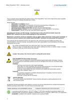
Safety XtrapulsPac™ SF01 - Operating manual ! This is a specific manual describing the Safety function of the XtrapulsPac™ servo drive range having output capability suitable for driving AC brushless sinusoidal servo motors. Please see also: o XtrapulsPac™ Installation manual o XtrapulsPac™ User Guide for the operation of the drive (commissioning, configuration, ...) o XtrapulsPac™Templates for the templates of target applications. o Gem Drive Studio software Quick Start manual for the drive parameterization. o EtherCAT® fieldbus interface manual for the XtrapulsPac™-et and XtrapulsPac™-ed versions....
Open the catalog to page 2
Safety XtrapulsPac™ SF01 - Operating manual In France, RECYLUM allows all professionals benefiting from a free collection and recycling solution, in observance of the regulation, the environment and health. Information and sorting instructions regarding INFRANOR Waste category Recyclable waste Recyclable waste Recyclable waste Recyclable waste Electronical boards and components WEEE (Waste Electronic and Electrical Equipment) Dangerous industrial waste Waste management Waste disposal centre / collection point of recyclable waste Waste disposal centre / collection point of recyclable waste Waste...
Open the catalog to page 3
Safety XtrapulsPac™ SF01 - Operating manual
Open the catalog to page 4
Safety XtrapulsPac™ SF01 - Operating manual
Open the catalog to page 5
Safety XtrapulsPac™ SF01 - Operating manual
Open the catalog to page 6
Safety XtrapulsPac™ SF01 - Operating manual 1.1 - SYSTEM OVERVIEW This manual describes the Safety functions (SS1, SS2, SOS, SLS, SDI, SBC) of the XtrapulsPac™ drive equipped with the optional safety board (SF option). These safety functions are SIL2 certified. The Safety board is available with the XtrapulsPac™-ed (EtherCAT® bus) and XtrapulsPac™-kd (CANopen® bus) servo drive versions. The XtrapulsPac™ optional safety board fulfills the standards IEC61800-5-2 and IEC61508. > The STO function SIL3 is available as standard and can be used without the safety board. > Two inputs STO1\, STO2\ are...
Open the catalog to page 7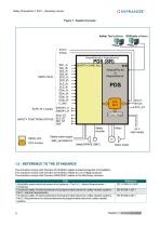
Safety XtrapulsPac™ SF01 - Operating manual Figure 1 - System Overview Safety Tool software GDStudio software Xtra puls Paced or XtrapulsPac-kd Safety inputs SAFETY FUNCTIONS STATUS logic supply Safety card Safety brake supply Motor brake The actuators comply with Directive 2014/30/EU related to Electromagnetic Compatibility. The actuators comply with Directive 2014/35/EU related to Low Voltage products. The actuators comply with Directive 2006/42/EC related to the Machinery directive. Chapter 1 - General description
Open the catalog to page 8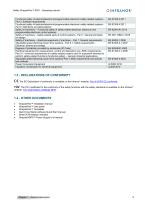
Safety XtrapulsPac™ SF01 - Operating manual C€ : The EC Declaration of conformity is available on the Infranor® website: Pac & GDPS CE conformity TUV: The TUV certificate for the conformity of the safety functions with the safety standards is available on the Infranor® website: TUV examination certificate SF01 • XtrapulsPac™ Installation manual • XtrapulsPac™ User guide • XtrapulsPac™ Templates • Gem Drive Studio software Quick Start manual • EtherCAT® fieldbus interface • XtrapulsGDPS™ Power Supply Unit manual Chapter 1 - General descriptio
Open the catalog to page 9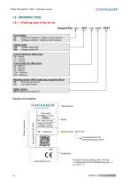
Safety XtrapulsPac™ SF01 - Operating manual 1.5 - ORDERING CODE 1.5.1 - Ordering code of the drives XtrapulsPac - xx – UUU / cc - mm – SF01 Drive version ed: EtherCAT® interface + digital encoder interface kd: CANopen interface + digital encoder interface Voltage range 230: Voltage range 230V 400: Voltage range 400V Current ratings for 230V drives 05 = 5Arms 11 = 11Arms 17 = 17Arms Current rating for 400V drives 08 = 08Arms 20 = 20Arms 45 = 45Arms 100 = 100Arms 200 = 200Arms Mounting version (400 V range only, except for 200 A) PT: Push-through version CP: Cold plate version Safety version SF01:...
Open the catalog to page 10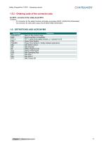
Safety XtrapulsPac™ SF01 - Operating manual FC-SF01: connector kit for safety board SF01 - S1 connector for the safety functions activation and status: B2CF 3.50/20/180 (Weidmuller) - S2 connector for safe brake output: BLZ5.08/04/180B (Weidmuller) Chapter 1 - General description
Open the catalog to page 11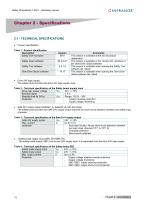
Safety XtrapulsPac™ SF01 - Operating manual Table 1 - Product identification
Open the catalog to page 12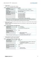
Safety XtrapulsPac™ SF01 - Operating manual • Position sensor: Digital encoder with Hiperface DSL® interface. Table 5 - Technical specification of the Position sensor
Open the catalog to page 13
Safety XtrapulsPac™ SF01 - Operating manual • Dynamic performance Table 8 - Response time
Open the catalog to page 14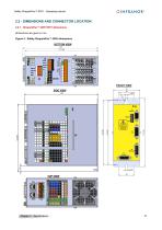
Safety XtrapulsPac™ SF01 - Operating manual 2.2 - DIMENSIONS AND CONNECTOR LOCATION 2.2.1 - XtrapulsPac™ 230V SF01 dimensions Dimensions are given in mm. Figure 2 - Safety XtrapulsPac™ 230V dimensions BOTTOM VIEW FRONT VIEW SIDE VIEW
Open the catalog to page 15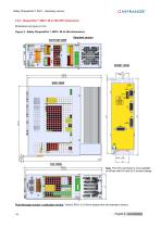
Safety XtrapulsPac™ SF01 - Operating manual Standard version :!■■■■■■■! □Liza !■■■■■■■! □□□□ •■■■■■■■I x Note: The X10 connector is only available on drives with 8 A and 20 A current ratings. Push-through version / cold plate version: Version SF01 is 33.5mm deeper than the standard version.
Open the catalog to page 16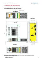
Safety XtrapulsPac™ SF01 - Operating manual Standard version SIDE VIEW Push-through version / cold plate version: Version SF01 is 33.5mm deeper than the standard version. Chapter 2 - Specif
Open the catalog to page 17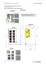
Safety XtrapulsPac™ SF01 - Operating manual Standard version Note: The dimensions of the SF01 version are the same as the standard version FRONT VIEW
Open the catalog to page 18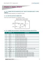
Safety XtrapulsPac™ SF01 - Operating manual Same wiring as standard XtrapulsPac™-ed / XtrapulsPac™-kd drives. Same wiring as standard XtrapulsPac™-ed / XtrapulsPac™-kd drives. 3.3 - S1: CONNECTOR FOR SAFETY FUNCTIONS ACTIVATION AND STATUS PIN Chapter 3 - Inputs - Outputs
Open the catalog to page 19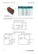
Safety XtrapulsPac™ SF01 - Operating manual Brand: Weidmuller Reference: B2CF 3.50/20/180 Signal location SS1_A\, SS1_B\, SS2_A\, SS2_B\, SOS_A\, SOS_B\, SLS_A\, SLS_B\, SOS_A\, SOS_B\, SDIp_A, SDIp_B, SDIn_A, SDIn_B: are opto-coupled inputs. SPECIFICATION OF THE LOGIC OUTPUTS 20 Chapter 3 - Inputs - Outputs
Open the catalog to page 20All Infranor Group catalogs and technical brochures
 XtrapulsPac_EN
4 Pages
 XtrapulsGemTemplates_e_1.4
21 Pages
 XtrapulsGem_User_Manual_v1.2.0.64
199 Pages
 XtrapulsGem_Inst_e_2.1
42 Pages
 XtrapulsGem_Inst_e_2.0
42 Pages
 SMTBSi-2Tz_en_2.1
43 Pages
 smt-100
32 Pages
 PacSimBox_d_1
1 Page
 Pac-SF01_flyer_en_18.02
4 Pages
 Pac_User_1.2.1.218
253 Pages
 Pac_Templates_en_1.9
27 Pages
 Pac_STO_Installation_en_2.2
13 Pages
 Pac_SF01_EN
4 Pages
 Pac_Installation_en_2.23
82 Pages
 Pac_flyer_en_17.12
4 Pages
 Option_CT_EMF
6 Pages
 MOVINOR_LH055_LH086_LH097_LH142
23 Pages
 ma_series
6 Pages
 GemSafeTorqueOff_en_1.1
12 Pages
 GemProgramming_e_1.1
47 Pages
 GDPS_old_version_1.1_1
11 Pages
 CD1pm_e_1.2(old)
18 Pages
 CD1pInst_e_7.2(old)
35 Pages
 CD1kInst_e_4.1(old)
40 Pages
 CD1k_CANopenProtocol_e_1.3(old)
86 Pages
 CD1a_e_7.1(old)
45 Pages
 Catalogue gamme SMT-BD1
11 Pages
 BM20A(F)v3_0
20 Pages
 BM20A(D)v3_0
20 Pages
 BF400(GB)v2_2
21 Pages
 BF400(D)v2_2
21 Pages
 BF230(GB)v2_0
23 Pages
 BF230(F)v2_0
23 Pages
 BD2m_e_2.2
69 Pages
 BD2m(GB)2.0
70 Pages
 BD2_e_3.2
53 Pages
 BD2(GB)3.1
53 Pages
 BD2(D)3.1
54 Pages
 Movinor_LH_e
4 Pages
 ma_series
6 Pages
 BD1t(GB)3.1
81 Pages
 BD1t(F)3.0
85 Pages
 BD1pInst(GB)3.0
25 Pages
 BD1pInst(F)3.0
23 Pages
 BD1pInst(D)3.0
24 Pages
 BD1pCD1pUse_e_2.4
57 Pages
 BD1m(GB)5.0
58 Pages
 BD1m(F)5.0
57 Pages
 BD1m(D)v3_3
64 Pages
 BD1k(GB)2.1
35 Pages
 BD1k(F)2.1
36 Pages
 BD1j(GB)v2_41
19 Pages
 BD1j(F)v2_4
21 Pages
 BD1i(GB)v2_21
23 Pages
 BD1i(F)v2_2
27 Pages
 BD1h(F)3.0
65 Pages
 BD1h(D)3.0
59 Pages
 BD1g(GB)v3_0
28 Pages
 BD1g(F)v3_0
28 Pages
 BD1a400(GB)v2_3
43 Pages
 BD1a400(F)v2_3
44 Pages
 BD1a400(D)v2_3
45 Pages
 BD1(GB)7.1_noPW
45 Pages
 BD1(GB)7.1
45 Pages
 BD1(F)7.1_noPW
47 Pages
 BD1(F)7.1
47 Pages
 BD1(D)7.1
45 Pages
 BD1 Katalog
11 Pages
 08ma_ms_e_01700
20 Pages
 Easy_User_5.0.1.60.2
190 Pages
 08ma_mrm_em_01575
20 Pages
 01ma_smv_e_01953
40 Pages
 PacHP-SF_Flyer_en_23.06
4 Pages
 IRD_User_Manual_en_1.2.XX.54.rev_b
216 Pages
 PacHP_User_en_1.2.8.100.b
280 Pages
 PacHP_SF02_operating_en_1.6
103 Pages
 PacHP_SF01_operating_en_2.0
63 Pages
 PacHP_Installation_en_2.9
91 Pages
 PacHP_Series_Brochure
8 Pages
 PacHP_Flyer_us_20.10
4 Pages
 IRD_Installation_en_1.5
42 Pages
 GDPS_Installation_en_4.4
18 Pages
 Easy_STO_en_1.4
14 Pages
 Easy_DB_STO_en_1.2
14 Pages
 Easy_DB_Installation_en_1.4
36 Pages
 CD1pmUser_en_4.2
55 Pages
 CD1pmInst_en_8.15
40 Pages
 CD1k_CANopenProtocol_en_2.10.1.1
108 Pages
 CD1pm_ProfibusProtocol_en_1.5
50 Pages
 CD1kUser_en_2.3
26 Pages
 CD1a_en_8.17
62 Pages
 CD1kInst_en_5.16
46 Pages
 CD1_STO_en_1.8
16 Pages
 CD1_flyer_en_14.09
4 Pages
 Braking_Resistors_en_1.5
10 Pages
 XtracontrolDC2_EN
4 Pages
 Flyer_VisiTouchCNC_EN_V1.1-1
2 Pages
 XtraforsWashdown_EN-2024
2 Pages
 DataSheet_CybIO_CNC_V1.0
6 Pages
 XtraforsPrime_EN-2024
2 Pages
 XtraforsMSS_EN
4 Pages
 XtraforsMSA_EN_2024
2 Pages
 XtraforsEx_EN-2024
2 Pages
 XtraforsBR_EN-2024
2 Pages
 XtraforsBL_EN-2024
2 Pages
 XtraforsBC-ed01-vs3
4 Pages
 Manual_XtraforsPrime
46 Pages
 Drawing_1
1 Page
 Datasheet_MSS
5 Pages
 Datasheet_2
2 Pages
 Datasheet_1
4 Pages
 BLSBLT_series
2 Pages
 BL220221
2 Pages
 BL270
BL2702 Pages
 BL190
BL1902 Pages
 bl100_series
6 Pages
 bl40_series
6 Pages
 BL30
BL302 Pages
 2019-01_XtraforsFP-DSL_FR
4 Pages
 Movinor_T_EN
4 Pages
 Movinor_N_EN
4 Pages
 Movinor_Low_Voltage_EN
4 Pages
 Manual Movinor T 03-2026
46 Pages
 Manual Movinor N 03-2026
63 Pages
 XtrapulsEasy™ AC servo-drive
4 Pages
 XtrapulsCD1 AC servo-drives
4 Pages
 CybIO
CybIO6 Pages
 AC SERVOMOTORS
2 Pages
 Movinor® N AC Servomotors
4 Pages






Archived catalogs
 AN_CD1ak_AbsoluteEncoder_en_2.0
10 Pages
 AN_CD1ak_SinCosTracks_e_1.0
7 Pages
 AN_CD1pm_AbsoluteEncoder_en_2.0
10 Pages
 AN_CD1pm_SinCosTracks_e_1.0
7 Pages
 AN_DC_bus_interfacing_en_1.3
5 Pages
 CD1_EC_conformity_24.05
1 Page
 CD1_STO_conformity_19.02
2 Pages
 EtherCAT Interface_en_1.3
20 Pages
 Easy_EC_Conformity_24_10
1 Page
 GDPS_EC_conformity_24.07
1 Page
 IRD_EC_Conformity_25.03
1 Page
 PacHP_TÜV_certificate_25.07
2 Pages
 BD1c(F)v2_01
19 Pages
 BD1c(GB)v2_01
19 Pages
 BD1d(F)v2_01
25 Pages
 BD1d(GB)v2_01
25 Pages
 BD1e(F)v2_01
22 Pages
 BD1f(F)v2_01
17 Pages
 BD1f(GB)v2_01
18 Pages
 CE_conformity_Gem
1 Page
 Pac_EC_conformity_25.04
1 Page
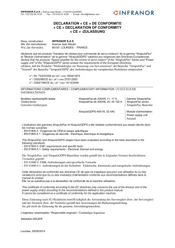 Pac_GDPS_CEconformity
1 Page
![SMT100D_e_1.01[1]](https://img.directindustry.com/pdf/repository_di/4620720/smt100d-e-101-1-1141223_1mg.jpg) SMT100D_e_1.01[1]
SMT100D_e_1.01[1]40 Pages
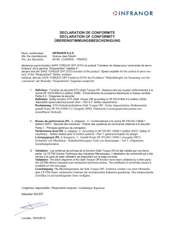 STO_declaration_Gem
2 Pages