
- Catalogs
- Infranor Group
- Manual Movinor N 03-2026


Manual Movinor N 03-2026

Manual Movinor N 03-2026
- Protection Levels: IP65 (standard), IP67, IP40.
- Thermal Sensors: Options include PTC (standard), NTC, KTY84-130 (discontinued), and PT1000.
- Certifications: UL listed and ATEX listed (EX).
- Connectivity: M5 air plug located on the rear cover.
- Fan Kit: Available for multiple motor sizes.
- Y-tec Angled Rotatable Hiperface INFRANOR.
- M23/M40 Angled Towards Shaft INFRANOR Sensorless.
- Y-tec Angled Rotatable Hiperface Universal.
- M23/M40 Angled Rotatable INFRANOR Sensorless.
- Y-tec Angled Rotatable BiSS-B Universal.
- M23/M40 17 Pole Straight INFRANOR Resolver.
- Y-tec Angled Rotatable QR12 SinCos without UVW Signals.
- Customer-specific options are available for each field.
- Document is subject to modifications as of March 12, 2026.
Catalog excerpts

Technical manual, mounting and first installation High Efficiency Pole Winding Synchronous Servomotors
Open the catalog to page 1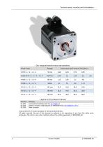
Technical manual, mounting and first installation Our range of synchronous servomotors Improvement of motors subject to technical alterations. All rights reserved. No part of this document is allowed to be reproduced in any form (by either print, photocopy, film shots or any other method) without the written agreement of INFRANOR SA.
Open the catalog to page 2
Technical manual, mounting and first installation
Open the catalog to page 3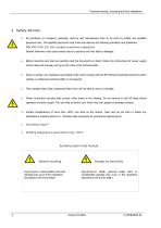
Technical manual, mounting and first installation ■ All operations on transport, assembly, start-up and maintenance have to be done by skilled and qualified personnel only. The qualified personnel must know and observe the following standards and guidelines: DIN VDE 0105, IEC 364, accident prevention regulations Deviant behaviour may cause serious injury to persons and may lead to damages. ■ Before mounting and start-up carefully read the documents on hand. Follow the instructions for power supply (motor label and manual) and go by the rules of the technical data. ■ Ensure a proper, low-impedance...
Open the catalog to page 4
Technical manual, mounting and first installation ■ Synchronous servomotors are precision motors. They are not intended to be connected directly to a rotary current power supply system. They have to be operated only by a particular electronic power stage. A direct connection to main supply will lead to the destruction of the motor. ■ To fit zero backlash drive elements strictly use the intended thread at the motor shaft and if possible warm up the drive elements. Only use suitable tools to fit the drive elements. ■ Avoid strong punches to the motor flange and the motor shaft. ■ Take care that...
Open the catalog to page 5
Technical manual, mounting and first installation 4. In General 4.1. About this manual This manual describes the synchronous servomotors of the N range and it is directed towards specialized staff having knowledge of electrical and mechanical engineering. The servomotors are operated together with the corresponding servo drives. Therefore absolutely follow the documentation of the servo drive too. If not stated in other unit all dimension to be understood in millimetre (mm). 4.2. Provisionary use Synchronous-servomotors are specially designed to run machines with high requirements to dynamics....
Open the catalog to page 6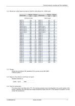
Technical manual, mounting and first installation Flange sizes according to IEC-standards, fit j6, accuracy as per DIN 42955 Tolerance grade: R The motor series N are fitted with a PTC. The overload protection has to be integrated in the control system of the inverter. Operation with rated data and a flange temperature higher than 65°C is only allowed in exception. For that contact the manufacturer.
Open the catalog to page 7
Technical manual, mounting and first installation Other windings are available on request. At the motor a supply voltage Udc <560V results into Io-current that requires a verification of the cable ampacity.
Open the catalog to page 8
Technical manual, mounting and first installation 3) Torque & length size: - C: 320V, D: 560V, W1: under specific windings list 1 W: a very large choice of different windings allowing us to adapt the motors to the particular requirements is available - 0: standard without keyway - 1: standard with keyway - 2: 11k6 x 23 without keyway, tapped hole M4 x 14 only N070 range! - 3: 11k6 x 23 with keyway, tapped hole M4 x 14 only N070 range! - 0: standard, 1: with shaft seal - 0: without brake, 1: with brake - R02: Resolver 2T safe mounting - H01: Hiperface Sick SEK34 Singleturn - H02: Hiperface Sick...
Open the catalog to page 9
Technical manual, mounting and first installation - Connectors orientation: - F: angled towards front (shaft) - B: angled towards back (rear) - Y: Ytec rotatable double receptacle - 01: M23 resolver, Infranor standard (power M23 or M40) - 02: M23 resolver, Mavilor FP compatible (power M23 or M40) - 03: M23 Hiperface, Infranor standard (power M23 or M40) - 04: M23 incremental, Infranor standard (power M23 or M40) - 05: M23 Incremental, Mavilor FP compatible (power M23 or M40) - 06: M23 or M40 Hiperface DSL, Infranor standard - 07: M23 or M40 sensorless, Infranor standard - 08: Ytec resolver, Infranor...
Open the catalog to page 10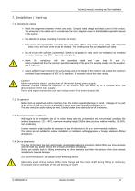
Technical manual, mounting and first installation 7. Installation / Start-up 7.1. Important notes Check the assignment between inverter and motor. Compare rated voltage and rated current of the devices. The wiring has to be carried out in accordance to the circuit diagram shown in the installation/operation manual of the inverter. Pay attention to proper grounding of inverter and motor. Place power and signal cables separately from each other. When using motor power cables with integrated brake wires, the brake wires should be shielded. The shielding braid has to be applied both-sided. Lay all...
Open the catalog to page 11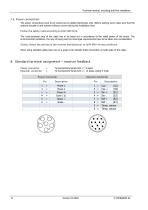
Technical manual, mounting and first installation The power connections have to be carried out by skilled electricians only. Before starting work make sure that the systems actually is and remains without current during the installation time. Follow the safety rules according to DIN VDE 0105. The cross-sectional area of the cable has to be layed out in accordance to the rated power of the motor. The environmental conditions, the way of laying and the local legal requirements have to be taken into consideration. Strictly follow the advices of the inverter manufacturer to fulfil EMV-wiring conditions....
Open the catalog to page 12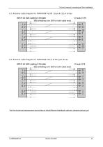
Technical manual, mounting and first installation 8.1. Resolver cable diagram for INFRANOR PacHP / Easy & CD1/k drives Take shielding over 360°on both cable ends For the terminal assignment according to the different feedback options, please contact us!
Open the catalog to page 13
Technical manual, mounting and first installation 8.3. Power connector according to the rated motor current If the rated motor current in the application is > 25Arms, the standard 1’’ M23 type 923 power connector/receptacle is no longer compatible - 1st alternative is cable output by PG thread M20 or M25 2nd alternative is 1,5’’ M40 type 940 connector/receptacle both depends on current value and on motor size Connectors/receptacles type: 1’’ M23 type 923 power connector = up to 25Arms 1,5’’ M40 type 940 power connector = up to 75Arms Power cables section: In case of cable 4,0mm² and 6,0mm², the...
Open the catalog to page 14All Infranor Group catalogs and technical brochures
 XtrapulsPac_EN
4 Pages
 SMTBSi-2Tz_en_2.1
43 Pages
 PacSimBox_d_1
1 Page
 Pac-SF01_flyer_en_18.02
4 Pages
 Pac_User_1.2.1.218
253 Pages
 Pac_Templates_en_1.9
27 Pages
 Pac_STO_Installation_en_2.2
13 Pages
 Pac_SF01_operating_en_1.6
63 Pages
 Pac_SF01_EN
4 Pages
 Pac_Installation_en_2.23
82 Pages
 Pac_flyer_en_17.12
4 Pages
 Option_CT_EMF
6 Pages
 MOVINOR_LH055_LH086_LH097_LH142
23 Pages
 ma_series
6 Pages
 GemSafeTorqueOff_en_1.1
12 Pages
 CD1pm_e_1.2(old)
18 Pages
 CD1pInst_e_7.2(old)
35 Pages
 CD1kInst_e_4.1(old)
40 Pages
 CD1k_CANopenProtocol_e_1.3(old)
86 Pages
 CD1a_e_7.1(old)
45 Pages
 Catalogue gamme SMT-BD1
11 Pages
 BM20A(F)v3_0
20 Pages
 BM20A(D)v3_0
20 Pages
 BF400(GB)v2_2
21 Pages
 BF400(D)v2_2
21 Pages
 BF230(GB)v2_0
23 Pages
 BF230(F)v2_0
23 Pages
 BD2m_e_2.2
69 Pages
 BD2m(GB)2.0
70 Pages
 BD2_e_3.2
53 Pages
 BD2(GB)3.1
53 Pages
 BD2(D)3.1
54 Pages
 Movinor_LH_e
4 Pages
 ma_series
6 Pages
 BD1t(GB)3.1
81 Pages
 BD1t(F)3.0
85 Pages
 BD1pInst(GB)3.0
25 Pages
 BD1pInst(F)3.0
23 Pages
 BD1pInst(D)3.0
24 Pages
 BD1pCD1pUse_e_2.4
57 Pages
 BD1m(GB)5.0
58 Pages
 BD1m(F)5.0
57 Pages
 BD1m(D)v3_3
64 Pages
 BD1k(GB)2.1
35 Pages
 BD1k(F)2.1
36 Pages
 BD1j(GB)v2_41
19 Pages
 BD1j(F)v2_4
21 Pages
 BD1i(GB)v2_21
23 Pages
 BD1i(F)v2_2
27 Pages
 BD1h(F)3.0
65 Pages
 BD1h(D)3.0
59 Pages
 BD1g(GB)v3_0
28 Pages
 BD1g(F)v3_0
28 Pages
 BD1a400(GB)v2_3
43 Pages
 BD1a400(F)v2_3
44 Pages
 BD1a400(D)v2_3
45 Pages
 BD1(GB)7.1_noPW
45 Pages
 BD1(GB)7.1
45 Pages
 BD1(F)7.1_noPW
47 Pages
 BD1(F)7.1
47 Pages
 BD1(D)7.1
45 Pages
 BD1 Katalog
11 Pages
 Easy_User_5.0.1.60.2
190 Pages
 01ma_smv_e_01953
40 Pages
 PacHP-SF_Flyer_en_23.06
4 Pages
 IRD_User_Manual_en_1.2.XX.54.rev_b
216 Pages
 PacHP_User_en_1.2.8.100.b
280 Pages
 PacHP_SF02_operating_en_1.6
103 Pages
 PacHP_SF01_operating_en_2.0
63 Pages
 PacHP_Installation_en_2.9
91 Pages
 PacHP_Series_Brochure
8 Pages
 PacHP_Flyer_us_20.10
4 Pages
 IRD_Installation_en_1.5
42 Pages
 Easy_STO_en_1.4
14 Pages
 Easy_DB_STO_en_1.2
14 Pages
 Easy_DB_Installation_en_1.4
36 Pages
 CD1pmUser_en_4.2
55 Pages
 CD1pmInst_en_8.15
40 Pages
 CD1k_CANopenProtocol_en_2.10.1.1
108 Pages
 CD1pm_ProfibusProtocol_en_1.5
50 Pages
 CD1kUser_en_2.3
26 Pages
 CD1a_en_8.17
62 Pages
 CD1kInst_en_5.16
46 Pages
 CD1_STO_en_1.8
16 Pages
 CD1_flyer_en_14.09
4 Pages
 Braking_Resistors_en_1.5
10 Pages
 XtracontrolDC2_EN
4 Pages
 Flyer_VisiTouchCNC_EN_V1.1-1
2 Pages
 XtraforsWashdown_EN-2024
2 Pages
 DataSheet_CybIO_CNC_V1.0
6 Pages
 XtraforsPrime_EN-2024
2 Pages
 XtraforsMSS_EN
4 Pages
 XtraforsMSA_EN_2024
2 Pages
 XtraforsEx_EN-2024
2 Pages
 XtraforsBR_EN-2024
2 Pages
 XtraforsBL_EN-2024
2 Pages
 XtraforsBC-ed01-vs3
4 Pages
 Manual_XtraforsPrime
46 Pages
 Drawing_1
1 Page
 Datasheet_MSS
5 Pages
 Datasheet_2
2 Pages
 Datasheet_1
4 Pages
 BLSBLT_series
2 Pages
 BL220221
2 Pages
 BL270
BL2702 Pages
 BL190
BL1902 Pages
 bl100_series
6 Pages
 bl40_series
6 Pages
 BL30
BL302 Pages
 2019-01_XtraforsFP-DSL_FR
4 Pages
 Movinor_T_EN
4 Pages
 Movinor_N_EN
4 Pages
 Movinor_Low_Voltage_EN
4 Pages
 Manual Movinor T 03-2026
46 Pages
 XtrapulsEasy™ AC servo-drive
4 Pages
 XtrapulsCD1 AC servo-drives
4 Pages
 CybIO
CybIO6 Pages
 AC SERVOMOTORS
2 Pages
 Movinor® N AC Servomotors
4 Pages






Archived catalogs
 AN_CD1ak_AbsoluteEncoder_en_2.0
10 Pages
 AN_CD1ak_SinCosTracks_e_1.0
7 Pages
 AN_CD1pm_AbsoluteEncoder_en_2.0
10 Pages
 AN_CD1pm_SinCosTracks_e_1.0
7 Pages
 AN_DC_bus_interfacing_en_1.3
5 Pages
 CD1_EC_conformity_24.05
1 Page
 CD1_STO_conformity_19.02
2 Pages
 EtherCAT Interface_en_1.3
20 Pages
 Easy_EC_Conformity_24_10
1 Page
 GDPS_EC_conformity_24.07
1 Page
 IRD_EC_Conformity_25.03
1 Page
 PacHP_TÜV_certificate_25.07
2 Pages
 BD1c(F)v2_01
19 Pages
 BD1c(GB)v2_01
19 Pages
 BD1d(F)v2_01
25 Pages
 BD1d(GB)v2_01
25 Pages
 BD1e(F)v2_01
22 Pages
 BD1f(F)v2_01
17 Pages
 BD1f(GB)v2_01
18 Pages
 Pac_EC_conformity_25.04
1 Page




















