
- Catalogs
- Infranor Group
- IRD_User_Manual_en_1.2.XX.54.rev_b


IRD_User_Manual_en_1.2.XX.54.rev_b

IRD_User_Manual_en_1.2.XX.54.rev_b
The IRD drive is designed to control motor torque and speed using a high-resolution position sensor. It supports various position sensor types, configurable via software, and can be connected to a PC through EtherCAT for parameter display and modification using the Optio software tool. The drive parameters are identified by an index and sub-index, with properties such as access type and length.
Architecture
The IRD drive is configurable and includes parameters for servo-loop, motor, sensor, communication, and I/O configuration. It can be controlled via CANopen or EtherCAT fieldbus, or digital I/Os, depending on the operation mode.
Commissioning
The commissioning process involves using the Optio software for parameterization. The software requires a minimum PC configuration and involves steps such as power supply configuration, motor parameter setting, servo loop setting, and application setting. Each step involves specific configurations like operating voltage, motor parameters, and servo loop gains.
Power Supply Configuration
The drive's operating voltage must match the drive voltage rating, with parameters for undervoltage fault and warning thresholds. These thresholds ensure the drive operates within safe voltage levels.
Motor Configuration
If the motor is listed in the catalog, it can be selected directly, setting parameters like position sensor and current limits. For unlisted motors, parameters must be manually configured, including current limits, speed limit, and winding inductance.
Position Sensor Configuration
The IRD drive supports various position sensors, including TTL encoders and Hall effect sensors. Configuration involves setting parameters like resolution and zero mark pitch, with auto-phasing procedures available for adjustments.
The document outlines the process for setting up and tuning a servo motor system to achieve optimal performance with minimal noise. Key parameters include motor torque constant, motor inertia, and load inertia, which are crucial for calculating servo loop gains. The auto-tuning process is emphasized, with specific configurations for different scenarios, such as vertical axes affected by gravity.
Auto-Tuning Execution:
Auto-tuning involves adjusting the drive's maximum current value and ensuring the drive is initially disabled to prevent damage. The procedure identifies motor and load specifications through small displacements and calculates appropriate gain values. Warnings are provided about potential motor displacement during tuning and the importance of setting current limitations post-tuning.
Auto-Tuning Processes:
1. Max Servo Loop Bandwidth: Involves iterative adjustments to speed measurement filters and bandwidth to achieve stable servo loop behavior.
2. Vertical Axis Tuning: Special considerations are made for vertical axes due to gravity, starting with low gain values and progressively increasing them.
3. Iterative Tuning: Begins with standard filter settings and adjusts based on stability, increasing bandwidth and sampling rate as needed.
Mechanical Resonance Filtering:
When using an anti-resonance filter, the relationship between sampling rate, bandwidth, and low-pass filter cut-off frequency is crucial. The document provides a chart for selecting appropriate values based on mechanical resonance analysis.
Servo Loop Sampling Rate:
The sampling rate affects servo loop stability and bandwidth. It should be significantly higher than the required bandwidth to ensure stability. Factors like sensor delay and mechanical coupling also influence the maximum achievable bandwidth.
Servo Loop Gains Adjustment:
Adjusting speed loop gains is critical due to their dependence on mechanical load characteristics. Parameters such as proportional speed gain, integral speed gain, and damping gain are defined, with guidance on their impact on system performance.
Conclusion:
The document provides detailed procedures and considerations for configuring and tuning servo motor systems, emphasizing the importance of careful parameter selection and iterative adjustments to achieve optimal performance and stability.
The document discusses the impact of speed measurement delay on operational gains, emphasizing the selection of the speed measurement filter time constant based on motor position sensor resolution and acceptable noise levels. Position loop gains are crucial for servo motor behavior during displacements, affecting factors like following error and position overshoot.
Gain Parameters
- Proportional Position Gain (KPp): Enhances axis stiffness and reduces following error.
- Feedforward Speed 1 Gain (KFp): Reduces following error during motor displacement, set to maximum post-autotuning.
- Feedforward Speed 2 Gain (KBv): Compensates for viscous friction, calculated post-autotuning.
- Feedforward Acceleration Gain (KAv): Reduces following error during acceleration/deceleration, calculated during autotuning.
User Position Scaling
Defines internal position and speed setpoints using "user unit" definitions, requiring a relationship between sensor data and user unit values.
Following Error Protection
Speed and position error thresholds are set to protect the drive and application, adjusted based on maximum error values measured during operation cycles.
Position Loop Feedback
Typically uses a motor-mounted position sensor, but can use a second sensor on the mechanical load for specific applications.
Encoder Configuration
Details the configuration of various encoder types (TTL, SinCos, HIPERFACE, ENDAT 2.2, Biss C) for position sensors, including parameters like Zero Mark pitch and Motor Position Scaling.
Quick Test of the Servo Drive
Describes enabling control via software or hardware, testing servo loop stability, and optimizing regulator gains manually or through autotuning.
Profile Parameters
Includes setting maximum velocity, acceleration, and deceleration parameters for both velocity and position profile modes, with options for trapezoidal or S-curve motion profiles.
Checking Servo Loop Stability
Outlines procedures for ensuring stability in both velocity and position modes, including adjustments for noise and mechanical resonances.
- Feedforward Control: Adjust the Feedforward acceleration gain (KAv) to 0 if noise occurs during acceleration/deceleration. Reduce Feedforward speed 1 value (KFp) to prevent position overshoot.
- Profile Modes: In Profile velocity mode, only speed regulator gains are active. In Profile position mode, both speed and position regulator gains are active. Auto-tuning in Velocity mode sets position loop gains to 0, disabling motor movement.
- Interpolated and Cyclic Synchronous Modes: Clear KAv manually post Auto-tuning if noise is significant during motor movement.
- After testing and validating motor parameters, add the motor to the catalog using the Add (+) command, entering and saving parameters manually.
- Inputs: Various inputs like ENABLE, INHIBIT, LIMIT SWITCH, HOME SWITCH, and others control motor functions. Proper voltage levels and polarity settings are crucial for correct operation.
- Outputs: Outputs like BRAKE, FAULT, WARNING, and others indicate motor and drive states. Output voltage can be adjusted between 3.3V and 5V.
- Parameters can be saved in non-volatile memory using the Store command. Backup and Restore commands manage file transfers between the drive and PC.
- USER_PAR.TXT file allows saving user-specific parameters not included in the standard DRIVEPAR.TXT file.
- Oscilloscope: A digital oscilloscope in PC software displays drive signals using Index/Sub-index identification.
- Dialog Terminal: Allows reading and writing parameter values on selected axes, supporting multiple parameters and axes simultaneously.
- Communication Objects: CAN telegrams consist of several fields including SOM, COB-ID, and data segment. Default COB-ID is 11 bits, with specific function codes for different objects.
- Network Management: NMT protocols manage network states and synchronization. SYNC messages provide network clock synchronization.
- Process Data Objects (PDO): Used for real-time data exchange, with RPDOs sent by the master and TPDOs by the drive. Each PDO is defined by communication parameters and mapping.
The document outlines the communication parameters for RPDOs and TPDOs, focusing on PDO COB-ID and Transmission Type. The COB-ID can be modified in the NMT Pre-Operational State and takes effect in the Operational State. Transmission types include cyclic, acyclic, synchronous, asynchronous, and RTR only.
PDO Transmission Modes
Synchronous transmission occurs with SYNC messages, while asynchronous transmission is independent. Event-driven and remotely requested modes are also described.
PDO Mapping
The mapping parameter's sub-index 0 contains the number of valid entries, which corresponds to the number of application variables transmitted/received. The structure of a PDO mapping entry includes index, sub-index, and object length.
Multiplexed Data
Multiplexed data allows multiple axis demand values in one message. The document provides examples of how to map objects for different axes using dummy objects.
Receive PDO Communication Parameters
Details for objects 0x1400 to 0x1403 are provided, including COB-ID and Transmission Type, with default values and access types.
Receive PDO Mapping
Objects 0x1600 to 0x1603 are described, detailing the number of mapped objects and default values.
Transmit PDO Parameters
Objects 0x1800 to 0x1803 are outlined, including COB-ID and Transmission Type, with default values.
Transmit PDO Mapping
Objects 0x1A00 to 0x1A03 are detailed, focusing on the number of mapped objects and default values.
Manufacturer PDO Transmission Mode
This mode controls the number of cyclic TPDOn for each axis, using TPDOn_Control and TPDO_Count.
Service Data Objects (SDO)
The SDO communication channel features a client/server relationship and an object dictionary. Node ID settings and SDO message redirection are discussed.
Emergency Objects
The document describes the structure of emergency messages, including error codes and manufacturer-specific error fields.
This section defines the behavior of the EMCY message with three possible values: 0 (no message sent), 1 (message sent on error), and 2 (message sent on error or error reset). The last case is not applicable for EtherCAT.
NodeGuarding Guard Time: Defines the guard time in milliseconds, multiplied by the lifetime factor, to determine the lifetime for the Life Guarding Protocol. Default is 0 if not used.
Lifetime Factor: Multiplied by the guard time to give the lifetime for the node guarding protocol. Default is 0 if not used.
Defines drive behavior when a Node guarding error occurs with values: 0 (No Operation), 1 (Drive Error), and 2 (Bus Stop state).
NMT State Machine: Describes communication status transitions from Power On to Operational state, including Pre-Operational and Stop states.
NMT Reset Configuration: Defines reset behavior of the drive, including Communication Reset and Warm Reset options.
NMT Message: Start/Pre-Op Remote Nodes: Sends an NMT message on the CAN bus to start or Pre-Op all nodes.
Signals that an NMT slave has entered the PRE-OPERATIONAL state after INITIALISING. A bootup message can be configured to be sent when the drive goes into Pre-Op state.
Drive State Machine: Describes the status and control sequence of the drive with states like NOT READY TO SWITCH ON, SWITCH ON DISABLED, READY TO SWITCH ON, SWITCHED ON, OPERATION ENABLE, QUICK STOP ACTIVE, FAULT REACTION ACTIVE, and FAULT.
State Transitions: Detailed transitions between states caused by internal events or host commands.
Control Word: Defines device control commands with bit patterns for operations like Shutdown, Switch On, Disable Voltage, Quick Stop, Disable Operation, Enable Operation, and Fault Reset.
Status Word: Indicates the current status of the drive with bits representing various states and conditions.
Allows linking specific bits in the control and status words to any bit of a signal, enabling custom configurations for device control and status monitoring.
The document describes a code array with two elements, each representing a target signal link for specific bits of a control word. Sub Index 1 links to bit 11, and Sub Index 2 links to bit 12. Both are of data type Unsigned32, accessible for read and write (Rw), and not mapped in PDO. The default value for both is 0x00000000. The structure for target signal entries includes a 16-bit index, an 8-bit sub-index, and a bit number (0-31). The index/sub-index must correspond to a variable object type that can be mapped in a RPDO.
An example is provided for copying bit 11 of the control word to a logic output, using the format 0x3045,1 = 0x60FE0111.
Errors are displayed in objects 0x3022,1 and 0x3022,2, with each bit corresponding to a specific error. An emergency message is sent with the last error code. Object 0x3025 allows error inhibition, triggering stops, and selecting errors not considered for AOK signal deactivation. Errors can be cleared by the "Reset Fault" bit in the control word (0x6040).
The document lists various errors with corresponding codes and troubleshooting steps. Errors range from hardware system errors to encoder and communication errors. Each error is associated with specific checks and corrective actions, such as verifying connections, checking voltage levels, and ensuring compliance with installation manual requirements.
The document emphasizes the importance of checking connections, voltage levels, and compliance with installation manuals to prevent errors. It also suggests specific actions for troubleshooting various errors, such as adjusting parameters and verifying wiring configurations.
This section defines the stop behavior when a DISABLE_OPERATION command is executed. The options include:
- 0: Disable operation
- 1: Stop on Slow down speed ramp
- 2: Stop on Quick Stop speed ramp
- 3: Stop on current limit
This section outlines the stop behavior when an Inhibit logic input is activated. The options are similar to the Disable Operation Option Code but include disabling the drive.
Parameters define the deceleration for a stop executed with stop option code 1 or 5. It includes two sub-indexes for future use.
This object defines the deceleration for a quick stop with Quick Stop Option Code 2 or 6.
Defines the current limit when a stop on current limit is performed. It includes two sub-indexes, with the second reserved for future use.
Defines the time limit for a stop operation to prevent incorrect detection if the axis is oscillating.
Includes Manufacturer Drive Data, which indicates peak and rated current, drive voltage, and power supply voltage thresholds.
Stored in object 0x6410, these parameters include motor manufacturer name, model, code, type, max speed, rated speed, stall current, peak current, torque constant, inertia, inductance, number of pole pairs, motor phase, and sensor offset.
Defines parameters controlling the motor, including number of pole pairs, motor phase, and motor offset.
These procedures calculate motor control parameters and are executed with specific signatures to avoid accidental activation.
Activated by setting a specific bit, this operation allows higher motor speed limits but reduces available torque.
Includes timing diagrams and parameters for drive and motor brake reaction times, with automatic control via control_word.
- Index 0x3307: This section describes the motor brake output control with four sub-indexes detailing parameters such as pull voltage, hold voltage, pull time, and switching frequency. Each parameter is defined with data type, access rights, and default values.
Motor Current Limits & Current Loop
- Index 0x6073 & 0x6075: Defines motor maximum and rated current. These parameters are crucial for calculating internal drive limitations.
- Index 0x3411 & 0x3412: Used for calculating current loop gains and drive current limitations based on motor parameters.
Current Loop Parameters
- Index 0x341C: Defines current loop bandwidth and filter settings, which are essential for current loop gain calculations.
- Index 0x60F6: Contains parameters for current loop settings, including proportional and integral gains for q-loop and d-loop.
PWM Frequency
- Index 0x31F6: Details PWM frequency settings, which affect drive performance and power losses. The default is 8kHz, with options for 4kHz and 16kHz based on specific application needs.
Torque Offset and Feedforward
- Index 0x60B2 & 0x30B4: Discusses torque offset and feedforward commands, which adjust the current command for the drive.
Dynamic Current Limits
- Index 0x30D1 & 0x342B: These objects allow dynamic limitation of motor current, with default and maximum values specified.
Motor Temperature Probe
- Index 0x3324: Configures motor temperature probe settings, including types and thresholds for warnings and errors.
The motor temperature is monitored in Celsius degrees using a Hiperface DSL encoder and motor temperature probe. The warning and error thresholds are set using specific indices.
IGBT Temperature Probe
The IGBT module temperature is monitored and returned as an integer value in Celsius.
Sensors
The IRD servo drive includes two sensor inputs for motor or position feedback. The position feedback sensor and motor feedback sensor can be selected and configured using specific indices.
Encoder Types and Parameters
Various encoder types are supported, including TTL Incremental Encoder, Sin-Cos Incremental Encoder, and Hiperface Encoder. Each encoder type has specific parameters and configurations, such as encoder type, configuration, virtual top Z shift, and zero mark pitch.
Encoder Position and Offset
The encoder position is monitored and can be adjusted using an offset. The position is calculated based on internal position and offset values.
TTL Encoder
TTL encoders can be used for motor or position feedback. Motor-phasing is required for motor feedback, while position feedback requires setting the encoder resolution.
Hall Effect Sensor
The Hall effect sensor is used with TTL or Sin-Cos encoders to avoid motor phase search during startup. Parameters include motor phase order and sensor offset.
Encoder with Digital Interface
Encoders with digital interfaces, such as Hiperface DSL and EnDAT 2.2, are supported on specific inputs. Parameters for these encoders include type, configuration, and maximum revolution.
The document outlines the configuration and protocols for Encoder 2, including supported protocols such as Hiperface DSL, EnDAT 2.2, BiSS-C, and Tamagawa. It details the encoder's position, offset, and data parameters, emphasizing the importance of setting these correctly for accurate position monitoring and feedback.
Encoder 2 Position and Offset
Encoder 2's position is calculated using internal position and offset values. The offset is crucial for aligning user and internal positions, especially in multi-turn absolute encoders where it is saved and restored at power on.
Encoder 2 Data
This section describes various sub-indexes related to Encoder 2, including error status, name, type, resolution, factor, maximum revolution, and specifications. These parameters are essential for ensuring compatibility and functionality with different encoder models.
Linear Absolute Digital Encoder
The document explains the use of linear absolute digital encoders for motor and position feedback. It highlights the need to adjust parameters like motor pole pitch and encoder distance for accurate feedback and scaling.
Absolute Multi-turn Position
Absolute encoders provide position values over one revolution, enabling immediate servo motor activation after power-up. The document stresses the importance of setting encoder zero positions to prevent overflow and ensure accurate positioning.
Position Factor and Units
The position factor is defined by numerator and denominator values, determining increments in user and motor units per revolution. This section provides examples for setting these parameters to achieve desired resolutions.
Reducer Ratio
The reducer ratio for rotary axes is detailed, with examples illustrating how to set input and output ratios for different mechanical setups.
Servo Loops
The document describes the structure and parameters of servo loops, including speed and position loop gains. It emphasizes the importance of adjusting these gains based on mechanical load characteristics to optimize performance and stability.
Index 0x31F1 defines the servo loops sampling rate with four elements. The current loop sampling rate is determined by the PWM frequency and cannot be modified. The position and speed loop sampling rate can be set to 2000, 4000, or 8000 Hz, affecting servo loop stability and bandwidth. Higher rates increase bandwidth but may affect stability due to other factors like motor position sensor resolution.
Index 0x60F9 outlines the speed loop parameters with eight elements, including proportional, integral, and derivative gains, and their respective filters. These parameters are adjustable within a range of 0 to 65535, allowing customization of the speed loop's response characteristics.
Index 0x30F9 describes a low-pass filter for the speed loop, with three elements defining cut-off frequencies between 20 and 1000 Hz. This filter helps manage the speed loop's response to changes in speed demand.
Index 0x30F8 provides monitoring capabilities for the speed loop, including speed set point, motor speed, speed loop error, and current command. It helps ensure the drive operates within specified parameters.
Index 0x60FB details the position control parameters, including proportional gain and feedforward gains for speed and acceleration. These parameters help reduce following errors during motor acceleration and deceleration.
Index 0x31FF allows selection between internal and external feedforward for speed and acceleration, providing flexibility in control strategies.
Index 0x31FB describes the integrator reset configuration for the speed loop, which can help reduce target position overshoot during positioning.
Indexes 0x3441 and 0x3442 provide status and configuration options for the device, including activation of specific functions like current limitation detection and motor zero speed detection.
The auto-tuning procedure identifies motor and mechanical load specifications to set appropriate gain values, optimizing the drive's performance.
The document outlines the auto-tuning configuration for servo systems, emphasizing the importance of selecting appropriate settings based on application requirements. Key factors include the type of position sensor, position resolution, motor-load coupling, and mechanical structure. The auto-tuning process should be iteratively adjusted to achieve optimal servo loop performance.
Auto-tuning Configuration
- Index 0x342A: Defines auto-tuning mode with options for legacy compatibility, standard mode, and vertical axis mode.
- Index 0x3425: Specifies parameters like bandwidth, filter type, speed filter, and application requirements. Bandwidth and filter type are crucial for stability and performance.
Auto-tuning Parameters
- Bandwidth selection ranges from low to high, affecting servo loop bandwidth.
- Filter types include standard, anti-resonance, and high stiffness, chosen based on mechanical coupling and resonance.
- Speed filter settings adjust cut-off frequency and time constant, with auto-select options based on sensor resolution and load specifications.
- Application requirements focus on minimizing tracking error or overshoot, depending on synchronization or positioning needs.
Auto-tuning Procedure
- Index 0x3426: Initiates the auto-tuning process with a specific signature to prevent accidental execution. The procedure's status can be monitored, and it can be aborted if necessary.
Parameter Storage and Restoration
- Parameters can be saved to and restored from internal flash memory using specific commands, ensuring consistent drive configurations.
Operation Modes
The document details various supported drive modes, including Profile Position, Velocity, Torque, Homing, and Cyclic Synchronous modes. Each mode has specific control and status word bits for operation.
Profile Position Mode
- Utilizes a trapezoidal or S-curve trajectory for positioning, with parameters like target position, max motor speed, profile velocity, and acceleration/deceleration settings.
- The mode allows for immediate setpoint changes and acknowledges new setpoints through control and status word bits.
This structured summary highlights the critical aspects of configuring and operating the IRD servo drive system, focusing on auto-tuning, parameter management, and supported operation modes.
1. Data Types and Object Classes: Various data types such as Unsigned32, Unsigned16, and Integer32 are used across different object classes like pp, pv, sm, and hm. Access is generally read/write (rw), and PDO mapping varies.
2. Position Window: Defines a symmetrical range around the target position. If the motor's current position is within this window, the target is considered reached.
3. Max Profile Velocity: Limits the maximum speed during profiled moves in various modes.
4. Position Profile Speed Modulation: Allows speed modulation of the profile generator in different modes.
5. Axis Type: Defines whether the axis is linear or rotating, affecting software position limits.
Procedures:
1. Homing Mode: Used to set the motor to a known position using various signals. The procedure is controlled by the homing method and involves specific trajectories.
2. Homing Speeds and Acceleration: Define the motor speed and acceleration during the homing process.
3. Homing Current Limit: Sets the current limit during homing on mechanical limits.
4. End on Home Position: Determines if the drive moves to the home position after homing.
Standards and Norms:
1. Position Reference Error Flag: Indicates errors related to position reference and can be reset by the host controller.
2. Interpolated Position Mode: Used for coordinated control of multiple axes, requiring real-time data flow and synchronization.
Recommendations:
1. Ensure proper configuration of homing methods and speeds for accurate positioning.
2. Monitor position reference error flags to detect and address errors promptly.
3. Utilize interpolated position mode for synchronized multi-axis control.
Key Parameters:
1. Position Window Time: Time within which the position must be maintained to set the target reached status.
2. Max Profile Velocity: Maximum allowable speed during moves.
3. Homing Method: Various methods available for different homing requirements.
4. Homing Current Limit: Defines the current limit during homing.
Limitations:
1. Position window control is inactive if the value is set to 0.
2. Homing errors can occur if the drive is not in "operation enabled" mode or if an unimplemented method is selected.
The document discusses various interpolation modes for CAN bus systems, including linear, PV, and P3 interpolation. Linear interpolation is optimal at low speeds, while PV and P3 support feedforward acceleration terms. The interpolation submode is selected via index 0x60C0, and data is recorded in index 0x60C1. The interpolated data output is at index 0x30C1, applied only in Interpolated Position Mode.
This mode allows operation with a velocity reference, closing only the speed and current loops. Key parameters include Velocity Demand Value (0x606B), Actual Velocity (0x606C), and Target Velocity (0x60FF). The Velocity Window and Threshold define acceptable velocity ranges, influencing status word bits for target achievement.
In this mode, the drive operates with current loops, without speed or position control. Target Torque (0x6071) is the input for the current loop, with parameters like Torque Slope (0x6087) defining torque change rates. The DC Voltage (0x6079) is monitored for system stability.
The document outlines Cyclic Synchronous Position (CSP), Velocity (CSV), and Torque (CST) Modes. CSP involves position control with interpolation, CSV focuses on velocity control, and CST emphasizes torque control. Each mode has specific object indices for target and actual values, with offsets for fine-tuning.
Sequence Mode enables pre-programmed moves, identified by sequence numbers. Sequences can be linked for complex operations, with start and end conditions defined by logic bit patterns. Control and status words manage sequence execution and completion.
The document outlines the management of sequence parameters stored in RAM memory, which can be set via a sequence file (SEQUENCE.TXT) or direct access through objects. Loading a sequence file erases existing parameters, while merging retains them unless specified in the file.
Object Definition
Objects control sequence execution, with specific indices for inputs, outputs, pulse configurations, and sequence types. Parameters are accessed through objects 0x3610 and 0x3611.
Positioning Sequence
Main parameters include position, speed, acceleration, deceleration, and delay time. Example sequences demonstrate configurations without stopping.
Homing Sequence
Parameters include home offset, method, speeds, acceleration, and current limit. The sequence operates in Homing Mode.
Speed Sequence
Parameters include speed setpoint, acceleration, deceleration, and running time. Running time of 65535 indicates infinite execution, with end conditions for exit.
Torque Sequence
Parameters include speed setpoint, acceleration, running time, and current limit. The sequence runs until current reaches the limit, with infinite holding time possible.
Gearing Sequence
Parameters include configuration, factor, acceleration, differential speed, and synchronization distances. Global parameters affect all gearing sequences.
Sequence Chaining
Controlled by SeqCount, SeqNext, SeqLink, and StartCond. Sequences link based on conditions, with examples provided for counter loops and conditional jumps.
The document outlines the configuration and parameters for sequence management in a technical system. Key parameters include:
- SeqNb (0x3610): Selects the sequence number (0-127).
- SeqType (0x3611-1): Defines the sequence type, such as Positioning (POS), Homing (HOME), Speed (SPEED), Torque (TORQUE), and Gear (GEAR).
- NextSeq (0x3611-2): Specifies the next sequence to execute if no condition or counter is present.
- SeqCount (0x3611-3): Indicates how many times the sequence should be executed, decrementing each time a sequence completes.
- SeqLink (0x3611-4): Specifies the sequence to execute when SeqCount is not zero.
- Trigger (0x3611-5): Defines the output triggering event.
- Output (0x3611-6 to 0x3611-8): Manages output bits for reset, set, and toggle actions.
- StartCond (0x3611-9 to 0x3611-10): Defines condition bits to start the sequence.
- Tempo (0x3611-23): Sets delay time in milliseconds at the end of positioning.
- EndCond (0x3611-11 to 0x3611-12): Defines condition bits to stop the sequence.
- Sequence Inputs (Index 0x3601): Includes sequence number input, executed sequence number, and conditional input.
- Sequence Outputs (Index 0x3602): Covers programmable logic outputs, polarity, dedicated logic outputs, and their polarity.
- Minimum Sequence Pulse (Index 0x3603): Defines the minimum duration of the SEQ output.
- Output Pulse Configuration (Index 0x3604): Configures output pulse and its duration.
- Sequence Phase (Index 0x3605): Monitors the state inside a sequence.
- Sequence Captured Position (Index 0x360B): Provides the value of the position captured by the torque sequence.
- Supported Sequence Types (Index 0x360F): Lists various sequence types supported by the firmware and drive model.
- Maximum Sequences Supported (Index 0x3612): Indicates the maximum number of sequences supported by a device.
Sequence files are text files with parameters defined by key-value pairs. Key points include:
- Parameters are defined with syntax:
Key_word = value. - Sequences begin with
SeqNband parameters can be declared in any order. - Incoherent parameters or values out of limits generate errors.
- Sequences can be loaded or merged into memory.
The IRD drive allows configuration of digital inputs and outputs, connecting physical logic inputs to variables and vice versa. Available logic input functions include Negative Limit Switch, Positive Limit Switch, Homing Switch, and Inhibit.
- General Commands: The update process involves writing and reading specific codes to change modes and verify support. The execution time can vary significantly depending on the operation, such as switching from firmware to bootmanager mode.
- Parameters: Includes the number of binary blocks, block types, sectors, and an erase command. The erase command has a long execution time.
- Parameters: Defines block type, buffer size, current sector, and address. Data transfer involves a segmented buffer.
- Initialization: Involves writing update codes and verifying program mode.
- Erase: Specifies the number of blocks, block types, and sectors mask, followed by an erase command.
- Programming: Repeated for each block, involves writing block type and data, followed by a program command.
- Communication: Lists various parameters related to CANopen identity, server and client SDO parameters, RPDO and TPDO mappings, and NMT configurations.
- General: Includes device type, manufacturer details, software and hardware versions, and parameter storage and restoration.
- Device Control: Covers control and status words, operation modes, device state monitoring, and various control configurations.
- Motor: Details motor data, parameters, and temperature monitoring.
- Sensors: Describes position feedback and motor feedback sensor selections.
- Encoders: Provides detailed configurations and status for multiple encoders.
- Servo Loops: Includes current and speed loop parameters, monitoring, and control.
- Position Control: Covers position control parameters, monitoring, and external feedforward.
- Auto-tuning: Describes auto-tuning configurations and parameters.
- Error Control: Details error monitoring, codes, and control masks.
- Profile Position Mode: Includes target position, speed, acceleration, deceleration, and position limits.
- Home Offset (0x607C): Defines the offset for the home position.
- Homing Method (0x6098): Specifies the method used for homing.
- Homing Speeds (0x6099): Includes two speeds: Speed during switch search (HomeSpd1) and speed during zero search (HomeSpd2).
- Homing Acceleration (0x609A): Sets the acceleration during homing.
- Home Current Limit (0x309C): Limits the current during homing.
- End On Home Position (0x309D): Indicates the end of the homing process.
- Offset Velocity (0x60B1): Sets the velocity offset.
- Target Velocity (0x60FF): Defines the desired velocity.
- Velocity Demand Value (0x606B): The demanded velocity value.
- Velocity Actual Value (0x606C): The actual measured velocity.
- Velocity Window (0x606D): Defines the acceptable range for velocity.
- Velocity Threshold (0x606F): Sets the threshold for velocity changes.
- Target Torque (0x6071): Specifies the desired torque.
- Torque Slope (0x6087): Defines the rate of change for torque.
- Torque Demand Value (0x6074): The demanded torque value.
- Torque Actual Value (0x6077): The actual measured torque.
- Sequence Inputs (0x3601): Includes sequence number input, executed sequence number, and conditional inputs.
- Sequence Outputs (0x3602): Configures programmable and dedicated logic outputs.
- Sequence Configuration (0x360C): Defines the configuration for sequences.
- Digital Inputs (0x60FD): Configures digital input settings.
- Digital Outputs (0x60FE): Configures digital output settings.
- Digital Cam Positions (0x30E0): Defines positions for digital cam operations.
- Oscillo Function Support (0x5800): Supports oscilloscope functions.
- Oscillo Trigger Configuration (0x5820): Configures triggers for oscilloscope operations.
- Update Firmware (0x5F30): Procedures for updating firmware.
Catalog excerpts
Warning This is a general manual describing a series of servo drives having output capability suitable for driving AC brushless sinusoidal servo motors. Please see also: -IRD Installation Guide for the hardware installation of the drive (mounting, wiring, …). -EtherCAT fieldbus interface manual for the IRD-eb version Instructions for storage, use after storage, commissioning as well as all technical details require the MANDATORY reading of the manual before getting the drives operational. Maintenance procedures should be attempted only by highly skilled technicians who have good knowledge of...
Open the catalog to page 2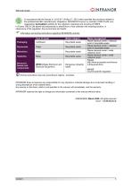
IRD User Guide OINFRANOR IRD User Guide OINFRANOR In accordance with the Decree nr. 2012-617 of May 2nd, 2012 which specifies the provisions related to the professional EEE manufacturers' obligations, INFRANOR France is a member of RECYLUM: ecoorganization ecosystem certified for the collection, treatment and recycling of WEEE. In France, RECYLUM allows all professionals to benefit from a free collection and recycling solution, in observance of the regulation, the environment and health. Information and sorting instructions regarding INFRANOR products Sorting instructions may vary according to...
Open the catalog to page 3
CHAPTER 1 - GENERAL DESCRIPTION 1.1 - Introduction The IRD drive directly controls the motor torque and speed from the information provided by a high-resolution position sensor. The sinusoidal current commutation generated from the information of this high-resolution position sensor ensures very smooth motor torque/force control. The IRD drive can be configured for the feedback of various position sensor types. The appropriate position sensor configuration is selectable by software and saved in the drive. ▪ With an incremental encoder only, a motor phasing procedure (Phasing) must be executed...
Open the catalog to page 6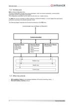
1.2 - Architecture IRD is a freely configurable drive. The drive configuration includes servo-loop parameters, motor and sensor parameters, communication parameters and I/O configuration parameters. The configuration parameters can be stored into the drive non- volatile memory. The IRD drive can be controlled via either CANopen or EtherCAT fieldbus, or via the digital I/Os (stand-alone positioner) according to the selected operation mode. The following diagram describes the functional architecture of the IRD drive: Communication bus (CANopen or EtherCAT) Standard Modes EtherCat Modes Manufacturer...
Open the catalog to page 7
IRD User Guide OINFRANOR This chapter describes the commissioning procedure of the drive by means of the Optio software. The Optio Drive Assistant software is PC compliant under Windows and allows an easy parameterization of the IRD drive range. Please see our website www.infranor.com for downloading the Optio software. Minimum Configuration The use of the Optio Drive Assistant software requires the minimum PC configuration described below: • 15" screen, 256 color screen, 1024x768 resolution • Windows Seven operating system • Microsoft .NET Framework V4.6.1 installed • 160 MB available on hard...
Open the catalog to page 8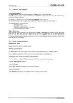
IRD User Guide OINFRANOR The Optio software allows the parameterization of all IRD drives for a given application. Each IRD drive of the Optio project is identified by its node ID. The node ID code values must all be different from each other in the same project. On the IRD, this NodeID is read from the EtherCAT EEPROM value at power-on. This EEPROM value can be changed using an EtherCAT master. The default NodeID value is “1”. The different software commands allow: - Opening an existing project, - Adding and/or removing axes in the project, Each parameter (object) of the drive can be defined...
Open the catalog to page 9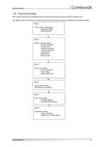
2.4 - Parameter Setting This chapter describes the parameterization procedure of the drive by means of the PC software tool. The different steps of the drive commissioning procedure and the sequence of operations are presented below. Step 1 : Power supply configuration -operating voltage -braking resistor Step 2 : Motor parameter setting -Position feedback -Current limits -Current loop gains -Thermal protection -I2t protection -Speed limit -Motor control Step 3 : Servo loop setting -Gains calculation -Auto-tuning -Gains adjustment Step 4 : User position scaling Following error protection Step...
Open the catalog to page 10
IRD User Guide 2.4.1 - Power supply configuration The Drive operating Voltage parameter value must be less than or equal to the drive voltage rating (24Vdc or 48Vdc). When this parameter is changed, the Overvoltage fault threshold and the Undervoltage fault threshold are modified accordingly. The Undervoltage fault threshold parameter defines the undervoltage fault level on the DC bus. When the DC bus voltage value drops below this parameter value, the drive Undervoltage fault is activated. When the DC bus voltage value goes above this parameter value, the drive Undervoltage fault is reset. The...
Open the catalog to page 11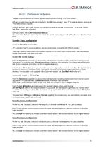
Position sensor configuration The IRD drive can operate with various position sensor types according to the drive version. Different encoder types can also be connected to the IRD drive encoder 1 input: TTL (square) signals, incremental + Hall effect sensor channels. Absolute encoders with digital interface can also be connected to the IRD drive encoder 2 or encoder 3 input. Only Biss C protocol is supported. For more details, refer to IRD Installation Manual. The used motor feedback sensor must be selected, enabled, and configured in the PC software tool as described below. Encoder 1 input configuration...
Open the catalog to page 12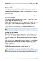
Motor parameters Current limit adjustment The Maximum current parameter defines the maximum output current value of the drive. It may vary between 20 % and 100 % of the drive’s current rating. The Rated current parameter defines the limitation threshold of the drive output RMS current (I 2t). It may vary between 20 % and 50 % of the drive’s current rating. Current loop adjustment Enter the value of the total phase-to-phase inductance connected to the drive (motor internal winding inductance + external filtering inductance if used). Select the current loop Bandwidth: -The High bandwidth selection...
Open the catalog to page 13All Infranor Group catalogs and technical brochures
 XtrapulsPac_EN
4 Pages
 SMTBSi-2Tz_en_2.1
43 Pages
 PacSimBox_d_1
1 Page
 Pac-SF01_flyer_en_18.02
4 Pages
 Pac_User_1.2.1.218
253 Pages
 Pac_Templates_en_1.9
27 Pages
 Pac_STO_Installation_en_2.2
13 Pages
 Pac_SF01_operating_en_1.6
63 Pages
 Pac_SF01_EN
4 Pages
 Pac_Installation_en_2.23
82 Pages
 Pac_flyer_en_17.12
4 Pages
 Option_CT_EMF
6 Pages
 MOVINOR_LH055_LH086_LH097_LH142
23 Pages
 ma_series
6 Pages
 GemSafeTorqueOff_en_1.1
12 Pages
 CD1pm_e_1.2(old)
18 Pages
 CD1pInst_e_7.2(old)
35 Pages
 CD1kInst_e_4.1(old)
40 Pages
 CD1k_CANopenProtocol_e_1.3(old)
86 Pages
 CD1a_e_7.1(old)
45 Pages
 Catalogue gamme SMT-BD1
11 Pages
 BM20A(F)v3_0
20 Pages
 BM20A(D)v3_0
20 Pages
 BF400(GB)v2_2
21 Pages
 BF400(D)v2_2
21 Pages
 BF230(GB)v2_0
23 Pages
 BF230(F)v2_0
23 Pages
 BD2m_e_2.2
69 Pages
 BD2m(GB)2.0
70 Pages
 BD2_e_3.2
53 Pages
 BD2(GB)3.1
53 Pages
 BD2(D)3.1
54 Pages
 Movinor_LH_e
4 Pages
 ma_series
6 Pages
 BD1t(GB)3.1
81 Pages
 BD1t(F)3.0
85 Pages
 BD1pInst(GB)3.0
25 Pages
 BD1pInst(F)3.0
23 Pages
 BD1pInst(D)3.0
24 Pages
 BD1pCD1pUse_e_2.4
57 Pages
 BD1m(GB)5.0
58 Pages
 BD1m(F)5.0
57 Pages
 BD1m(D)v3_3
64 Pages
 BD1k(GB)2.1
35 Pages
 BD1k(F)2.1
36 Pages
 BD1j(GB)v2_41
19 Pages
 BD1j(F)v2_4
21 Pages
 BD1i(GB)v2_21
23 Pages
 BD1i(F)v2_2
27 Pages
 BD1h(F)3.0
65 Pages
 BD1h(D)3.0
59 Pages
 BD1g(GB)v3_0
28 Pages
 BD1g(F)v3_0
28 Pages
 BD1a400(GB)v2_3
43 Pages
 BD1a400(F)v2_3
44 Pages
 BD1a400(D)v2_3
45 Pages
 BD1(GB)7.1_noPW
45 Pages
 BD1(GB)7.1
45 Pages
 BD1(F)7.1_noPW
47 Pages
 BD1(F)7.1
47 Pages
 BD1(D)7.1
45 Pages
 BD1 Katalog
11 Pages
 Easy_User_5.0.1.60.2
190 Pages
 01ma_smv_e_01953
40 Pages
 PacHP-SF_Flyer_en_23.06
4 Pages
 PacHP_User_en_1.2.8.100.b
280 Pages
 PacHP_SF02_operating_en_1.6
103 Pages
 PacHP_SF01_operating_en_2.0
63 Pages
 PacHP_Installation_en_2.9
91 Pages
 PacHP_Series_Brochure
8 Pages
 PacHP_Flyer_us_20.10
4 Pages
 IRD_Installation_en_1.5
42 Pages
 Easy_STO_en_1.4
14 Pages
 Easy_DB_STO_en_1.2
14 Pages
 Easy_DB_Installation_en_1.4
36 Pages
 CD1pmUser_en_4.2
55 Pages
 CD1pmInst_en_8.15
40 Pages
 CD1k_CANopenProtocol_en_2.10.1.1
108 Pages
 CD1pm_ProfibusProtocol_en_1.5
50 Pages
 CD1kUser_en_2.3
26 Pages
 CD1a_en_8.17
62 Pages
 CD1kInst_en_5.16
46 Pages
 CD1_STO_en_1.8
16 Pages
 CD1_flyer_en_14.09
4 Pages
 Braking_Resistors_en_1.5
10 Pages
 XtracontrolDC2_EN
4 Pages
 Flyer_VisiTouchCNC_EN_V1.1-1
2 Pages
 XtraforsWashdown_EN-2024
2 Pages
 DataSheet_CybIO_CNC_V1.0
6 Pages
 XtraforsPrime_EN-2024
2 Pages
 XtraforsMSS_EN
4 Pages
 XtraforsMSA_EN_2024
2 Pages
 XtraforsEx_EN-2024
2 Pages
 XtraforsBR_EN-2024
2 Pages
 XtraforsBL_EN-2024
2 Pages
 XtraforsBC-ed01-vs3
4 Pages
 Manual_XtraforsPrime
46 Pages
 Drawing_1
1 Page
 Datasheet_MSS
5 Pages
 Datasheet_2
2 Pages
 Datasheet_1
4 Pages
 BLSBLT_series
2 Pages
 BL220221
2 Pages
 BL270
BL2702 Pages
 BL190
BL1902 Pages
 bl100_series
6 Pages
 bl40_series
6 Pages
 BL30
BL302 Pages
 2019-01_XtraforsFP-DSL_FR
4 Pages
 Movinor_T_EN
4 Pages
 Movinor_N_EN
4 Pages
 Movinor_Low_Voltage_EN
4 Pages
 Manual Movinor T 03-2026
46 Pages
 Manual Movinor N 03-2026
63 Pages
 XtrapulsEasy™ AC servo-drive
4 Pages
 XtrapulsCD1 AC servo-drives
4 Pages
 CybIO
CybIO6 Pages
 AC SERVOMOTORS
2 Pages
 Movinor® N AC Servomotors
4 Pages






Archived catalogs
 AN_CD1ak_AbsoluteEncoder_en_2.0
10 Pages
 AN_CD1ak_SinCosTracks_e_1.0
7 Pages
 AN_CD1pm_AbsoluteEncoder_en_2.0
10 Pages
 AN_CD1pm_SinCosTracks_e_1.0
7 Pages
 AN_DC_bus_interfacing_en_1.3
5 Pages
 CD1_EC_conformity_24.05
1 Page
 CD1_STO_conformity_19.02
2 Pages
 EtherCAT Interface_en_1.3
20 Pages
 Easy_EC_Conformity_24_10
1 Page
 GDPS_EC_conformity_24.07
1 Page
 IRD_EC_Conformity_25.03
1 Page
 PacHP_TÜV_certificate_25.07
2 Pages
 BD1c(F)v2_01
19 Pages
 BD1c(GB)v2_01
19 Pages
 BD1d(F)v2_01
25 Pages
 BD1d(GB)v2_01
25 Pages
 BD1e(F)v2_01
22 Pages
 BD1f(F)v2_01
17 Pages
 BD1f(GB)v2_01
18 Pages
 Pac_EC_conformity_25.04
1 Page




















