- Catalogs
- Infranor Group
- IRD_Installation_en_1.5


IRD_Installation_en_1.5

IRD_Installation_en_1.5
- Diagnostic Coverage: Specifies a diagnostic coverage of 95% as per EN ISO 13849-1 standards.
- Periodic Inspection Routine: Safety function checks every three months and during machine safety function validation, ensuring all subsystems are operational.
- Residual Risk: Risk of motor shaft rotation up to 360° in case of a short-circuit between power transistors.
- STO Safety Function: Removes motor torque without shutting down the power supply, requiring both STO inputs connected to a +24V supply.
- SBC Safety Function: Activates a safety output to maintain the motor at standstill when torque is removed, activated with the STO function.
- LED Indicators: Red and green LEDs indicate operational status, faults, and communication states for EtherCAT and CANopen fieldbus.
- Connectors: Details for encoder ports, digital inputs/outputs, motor brake output, and thermal sensor input, with voltage and current specifications.
- Wiring Instructions: Guidelines for cable types and lengths, emphasizing shielded cables and proper grounding for EMC compliance.
- Connection Diagrams: Examples for connecting to EtherCAT and CANopen fieldbus and various sensor types.
- Ensure proper polarity between power supply and drives to avoid damage.
- Motor and brake cables must be shielded and connected to ground reference potential.
Catalog excerpts
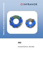
DIGITAL SERVO DRIVES FOR BRUSHLESS AC MOTORS Installation Guide
Open the catalog to page 1
IRD-eb Installation guide This is a general manual describing a series of servo drives having output capability suitable for driving AC brushless sinusoidal servo motors Warning Please see also: IRD User Guide for the operation of the drive (commissioning, configuration, ...) EtherCAT fieldbus interface manual Instructions for storage, use after storage, commissioning as well as all technical details require the MANDATORY reading of the manual before getting the drives operational. Maintenance procedures should be attempted only by highly skilled technicians having good knowledge of electronics...
Open the catalog to page 2
IRD-eb Installation guide All electrical industrial automated systems whose lifetime is coming to its end are Waste Electronic and Electrical Equipment (WEEE) according to article R543-172 of the French Environmental Code. WASTE DISPOSAL This symbol indicates that INFRANOR devices shall be eliminated by selective disposal and not with household waste. WEEE classification of the INFRANOR products Category 9: Monitoring and control instruments In accordance with the Decree nr. 2012-617 of May 2nd, 2012 which specifies the provisions related to the professional EEE manufacturers' obligations, INFRANOR...
Open the catalog to page 3
IRD-eb Installation guide
Open the catalog to page 4
IRD-eb Installation guide_ OINFRANOR
Open the catalog to page 5
IRD-eb Installation guide CHAPTER 1 - GENERAL 1.1 - INTRODUCTION IRD all-digital drives with sinusoidal PWM control are servo drives that provide the control of brushless AC motors with a position sensor. The standard control interface can be EtherCAT1 or 2CANopen, The IRD drive can be used in following typical applications: • • Axes controlled by EtherCAT or CANopen fieldbus, Stand-alone operation as a sequencer with control by means of logic I/Os, The configuration and parameterization software tool Optio allows a quick configuration of the IRD drives according to the target application. Thanks...
Open the catalog to page 6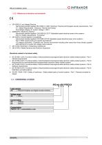
IRD-eb Installation guide 1.2.2 - Reference to directives and standards 2014/35/EU: Low Voltage Directive Harmonized standard applied: EN 61800-5-1:2007: Electrical, Thermal and Energetic security requirements - Part 5-1: Safety Requirements - Electrical, Thermal and Energy Overvoltage category III, System Voltage = 300 V 2006/42/EC: Machinery directive Harmonized standard applied: EN 61800-5-2:2017: Adjustable speed electrical power drive systems – Part 5-2: Safety requirements - Functional 2014/30/EU: Electromagnetic Compatibility Harmonized standard applied: EN 61800-3:2018: Adjustable speed...
Open the catalog to page 7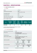
IRD-eb Installation guide OINFRANOR
Open the catalog to page 8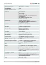
IRD-eb Installation guide OINFRANOR Maximum current frequency 500 Hz (Nondual use limitation) Drive reaction time (initialization delay before PWM on)
Open the catalog to page 9
IRD-eb Installation guide 2.1.3 - Thermal mounting specifications Cooling : Natural air convection The surrounding air temperature should never exceed 60°C. This typically refers to the air temperature near to the IRD drive or inside the robot. Cooling : Cold plate The IRD drives must be mounted to a structure (heatsink, motor, machine structure…) that should never exceed 70°C. For a proper running of the drive, the following specifications shall be fulfilled: - The contact surface between the drive and the mounting structure shall be at least as large as the drive heatsink. - The planarity of...
Open the catalog to page 10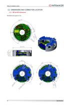
IRD-eb Installation guide 2.2 - DIMENSIONS AND CONNECTOR LOCATION 2.2.1 - IRD-eb-48/24 dimensions Dimensions are given in mm.
Open the catalog to page 11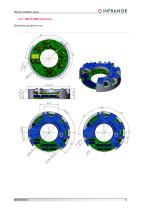
IRD-eb Installation guide OINFRANOR
Open the catalog to page 12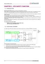
IRD-eb Installation guide CHAPTER 3 - STO SAFETY FUNCTION 3.1 - INTRODUCTION Safe Torque Off (STO) definition according to the EN 61800-5-2 standard: "Power, which can cause the rotation of a motor (or displacement in the case of a linear motor), is not applied to the motor. The drive will not provide energy to the motor which can generate torque (or force in the case of a linear motor)". Used alone, the STO function corresponds to an uncontrolled stopping in accordance with the stop category 0 of the EN 60204-1 standard. The STO function may be used where power removal is required to prevent...
Open the catalog to page 13
IRD-eb Installation guide OINFRANOR The integration of the STO function must be the result of a risk analysis of the complete machine. All control components must comply with the requirements of this risk analysis. Installing and commissioning of safety functions must be performed by skilled personnel only. Short-circuit avoidance: Install the drive in a control cabinet with a minimum IP54 protection. Avoid different control signals proximity. Any short-circuit between two control signals must be detected: - By the circuit-breaking system (fuse for example). In this case, the voltage reference...
Open the catalog to page 14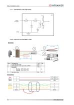
IRD-eb Installation guide OINFRANOR 3.3.2.1 - Specification of the logic inputs 3.3.2.2 - EtherCAT and STO-SBC-in cable
Open the catalog to page 15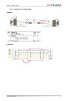
IRD-eb Installation guide OINFRANOR Shield recovery
Open the catalog to page 16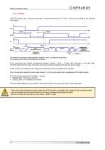
IRD-eb Installation guide 3.3.3 - Timings The STO function has a maximum activation / release response time of 10ms / 2ms max according to the following chronogram : A functional incoherence state between channels 1 and 2 is allowed during 50ms. The response time of the monitoring part is 200ms. If the monitoring part detects incoherence between channel 1 and 2, it locks both channels in the safe state. The STO fault cannot be reset. This state can only be exited by shutting down the 24V power supply. At this moment, the problem at the origin of this fault state must be identified and corrected....
Open the catalog to page 17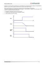
IRD-eb Installation guide OINFRANOR Used alone, the STO function corresponds to an uncontrolled stop in accordance with stop category 0 of the EN 60204-1 standard. So, this function is suited to machines with low inertia or high resistive torque. When using high inertia or low resistive torque machines, the user should initiate a controlled stop. To achieve a controlled stop in accordance with stop category 1 of the EN 60204-1 standard, the control system of the machine must generate the following sequences: ■ Deceleration of the load by means of the drive control, ■ Disabling of the PWM when...
Open the catalog to page 18All Infranor Group catalogs and technical brochures
 XtrapulsPac_EN
4 Pages
 XtrapulsGemTemplates_e_1.4
21 Pages
 XtrapulsGem_User_Manual_v1.2.0.64
199 Pages
 XtrapulsGem_Inst_e_2.1
42 Pages
 XtrapulsGem_Inst_e_2.0
42 Pages
 SMTBSi-2Tz_en_2.1
43 Pages
 smt-100
32 Pages
 PacSimBox_d_1
1 Page
 Pac-SF01_flyer_en_18.02
4 Pages
 Pac_User_1.2.1.218
253 Pages
 Pac_Templates_en_1.9
27 Pages
 Pac_STO_Installation_en_2.2
13 Pages
 Pac_SF01_operating_en_1.6
63 Pages
 Pac_SF01_EN
4 Pages
 Pac_Installation_en_2.23
82 Pages
 Pac_flyer_en_17.12
4 Pages
 Option_CT_EMF
6 Pages
 MOVINOR_LH055_LH086_LH097_LH142
23 Pages
 ma_series
6 Pages
 GemSafeTorqueOff_en_1.1
12 Pages
 GemProgramming_e_1.1
47 Pages
 GDPS_old_version_1.1_1
11 Pages
 CD1pm_e_1.2(old)
18 Pages
 CD1pInst_e_7.2(old)
35 Pages
 CD1kInst_e_4.1(old)
40 Pages
 CD1k_CANopenProtocol_e_1.3(old)
86 Pages
 CD1a_e_7.1(old)
45 Pages
 Catalogue gamme SMT-BD1
11 Pages
 BM20A(F)v3_0
20 Pages
 BM20A(D)v3_0
20 Pages
 BF400(GB)v2_2
21 Pages
 BF400(D)v2_2
21 Pages
 BF230(GB)v2_0
23 Pages
 BF230(F)v2_0
23 Pages
 BD2m_e_2.2
69 Pages
 BD2m(GB)2.0
70 Pages
 BD2_e_3.2
53 Pages
 BD2(GB)3.1
53 Pages
 BD2(D)3.1
54 Pages
 Movinor_LH_e
4 Pages
 ma_series
6 Pages
 BD1t(GB)3.1
81 Pages
 BD1t(F)3.0
85 Pages
 BD1pInst(GB)3.0
25 Pages
 BD1pInst(F)3.0
23 Pages
 BD1pInst(D)3.0
24 Pages
 BD1pCD1pUse_e_2.4
57 Pages
 BD1m(GB)5.0
58 Pages
 BD1m(F)5.0
57 Pages
 BD1m(D)v3_3
64 Pages
 BD1k(GB)2.1
35 Pages
 BD1k(F)2.1
36 Pages
 BD1j(GB)v2_41
19 Pages
 BD1j(F)v2_4
21 Pages
 BD1i(GB)v2_21
23 Pages
 BD1i(F)v2_2
27 Pages
 BD1h(F)3.0
65 Pages
 BD1h(D)3.0
59 Pages
 BD1g(GB)v3_0
28 Pages
 BD1g(F)v3_0
28 Pages
 BD1a400(GB)v2_3
43 Pages
 BD1a400(F)v2_3
44 Pages
 BD1a400(D)v2_3
45 Pages
 BD1(GB)7.1_noPW
45 Pages
 BD1(GB)7.1
45 Pages
 BD1(F)7.1_noPW
47 Pages
 BD1(F)7.1
47 Pages
 BD1(D)7.1
45 Pages
 BD1 Katalog
11 Pages
 08ma_ms_e_01700
20 Pages
 Easy_User_5.0.1.60.2
190 Pages
 08ma_mrm_em_01575
20 Pages
 01ma_smv_e_01953
40 Pages
 PacHP-SF_Flyer_en_23.06
4 Pages
 IRD_User_Manual_en_1.2.XX.54.rev_b
216 Pages
 PacHP_User_en_1.2.8.100.b
280 Pages
 PacHP_SF02_operating_en_1.6
103 Pages
 PacHP_SF01_operating_en_2.0
63 Pages
 PacHP_Installation_en_2.9
91 Pages
 PacHP_Series_Brochure
8 Pages
 PacHP_Flyer_us_20.10
4 Pages
 GDPS_Installation_en_4.4
18 Pages
 Easy_STO_en_1.4
14 Pages
 Easy_DB_STO_en_1.2
14 Pages
 Easy_DB_Installation_en_1.4
36 Pages
 CD1pmUser_en_4.2
55 Pages
 CD1pmInst_en_8.15
40 Pages
 CD1k_CANopenProtocol_en_2.10.1.1
108 Pages
 CD1pm_ProfibusProtocol_en_1.5
50 Pages
 CD1kUser_en_2.3
26 Pages
 CD1a_en_8.17
62 Pages
 CD1kInst_en_5.16
46 Pages
 CD1_STO_en_1.8
16 Pages
 CD1_flyer_en_14.09
4 Pages
 Braking_Resistors_en_1.5
10 Pages
 XtracontrolDC2_EN
4 Pages
 Flyer_VisiTouchCNC_EN_V1.1-1
2 Pages
 XtraforsWashdown_EN-2024
2 Pages
 DataSheet_CybIO_CNC_V1.0
6 Pages
 XtraforsPrime_EN-2024
2 Pages
 XtraforsMSS_EN
4 Pages
 XtraforsMSA_EN_2024
2 Pages
 XtraforsEx_EN-2024
2 Pages
 XtraforsBR_EN-2024
2 Pages
 XtraforsBL_EN-2024
2 Pages
 XtraforsBC-ed01-vs3
4 Pages
 Manual_XtraforsPrime
46 Pages
 Drawing_1
1 Page
 Datasheet_MSS
5 Pages
 Datasheet_2
2 Pages
 Datasheet_1
4 Pages
 BLSBLT_series
2 Pages
 BL220221
2 Pages
 BL270
BL2702 Pages
 BL190
BL1902 Pages
 bl100_series
6 Pages
 bl40_series
6 Pages
 BL30
BL302 Pages
 2019-01_XtraforsFP-DSL_FR
4 Pages
 Movinor_T_EN
4 Pages
 Movinor_N_EN
4 Pages
 Movinor_Low_Voltage_EN
4 Pages
 Manual Movinor T 03-2026
46 Pages
 Manual Movinor N 03-2026
63 Pages
 XtrapulsEasy™ AC servo-drive
4 Pages
 XtrapulsCD1 AC servo-drives
4 Pages
 CybIO
CybIO6 Pages
 AC SERVOMOTORS
2 Pages
 Movinor® N AC Servomotors
4 Pages






Archived catalogs
 AN_CD1ak_AbsoluteEncoder_en_2.0
10 Pages
 AN_CD1ak_SinCosTracks_e_1.0
7 Pages
 AN_CD1pm_AbsoluteEncoder_en_2.0
10 Pages
 AN_CD1pm_SinCosTracks_e_1.0
7 Pages
 AN_DC_bus_interfacing_en_1.3
5 Pages
 CD1_EC_conformity_24.05
1 Page
 CD1_STO_conformity_19.02
2 Pages
 EtherCAT Interface_en_1.3
20 Pages
 Easy_EC_Conformity_24_10
1 Page
 GDPS_EC_conformity_24.07
1 Page
 IRD_EC_Conformity_25.03
1 Page
 PacHP_TÜV_certificate_25.07
2 Pages
 BD1c(F)v2_01
19 Pages
 BD1c(GB)v2_01
19 Pages
 BD1d(F)v2_01
25 Pages
 BD1d(GB)v2_01
25 Pages
 BD1e(F)v2_01
22 Pages
 BD1f(F)v2_01
17 Pages
 BD1f(GB)v2_01
18 Pages
 CE_conformity_Gem
1 Page
 Pac_EC_conformity_25.04
1 Page
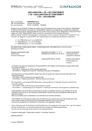 Pac_GDPS_CEconformity
1 Page
![SMT100D_e_1.01[1]](https://img.directindustry.com/pdf/repository_di/4620720/smt100d-e-101-1-1141223_1mg.jpg) SMT100D_e_1.01[1]
SMT100D_e_1.01[1]40 Pages
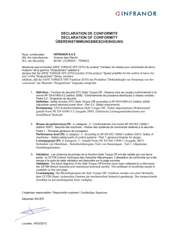 STO_declaration_Gem
2 Pages