
- Catalogs
- Infranor Group
- AN_IRD_ConfigurationWithJoints_RobotArm_03.26


AN_IRD_ConfigurationWithJoints_RobotArm_03.26

AN_IRD_ConfigurationWithJoints_RobotArm_03.26
IRD servo drives by INFRANOR are designed for integration into Haozhi joints with high ratio reducers. The setup process depends on the joint position sensor configuration, either using motor position feedback alone or with an additional sensor on the reducer output. The document is structured into three parts: joint setup without load, axis tuning on the robot arm, and online tuning optimization during operation.
Prerequisites: Ensure IRD drives have firmware 1.2.18.54 or higher, use the latest OPTIO version, and disconnect the EtherCAT master during commissioning.
Step 1: Motor Parameters Setting
- Case 1: For cataloged motors, select from the list and verify parameters.
- Case 2: For non-cataloged motors, manually adjust parameters using motor data.
Step 2: Motor Parameters Protected Storage
Secure motor and reducer parameters to prevent overwriting.
Step 3: Servo Loop Setting
Configure the position loop sensor and ensure correct User Position Scaling and Reducer ratio.
Step 4: Quick Test of the Joint
Perform a test in Profile Position Mode to verify setup accuracy.
Prerequisites: Complete joint commissioning and testing without load.
Step 1: Servo Loop Autotuning in "Critical" Position
Identify the critical position for stability and perform autotuning.
Step 2: Servo Loop Adjustment
Fine-tune control loops to prevent vibration and position lag.
Step 3: Servo Loop Parameters Saving
Save adjusted parameters to maintain tuning settings.
Step 4: Avoid Axis Falling
Ensure proper brake control to prevent axis falling during tuning.
Step 1: CANopen Fieldbus Wiring
Ensure proper wiring between drives for communication.
Step 2: Online Servo Loop Tuning
Optimize tuning while the robot is operational to enhance performance.
- After auto-tuning, set the notch filter based on the FFT curve if needed.
- Increase Bandwidth and Tuning levels to a higher value without causing noise, typically 80% is a good compromise.
- Higher Bandwidth and Tuning levels result in a high KPp gain value for the position loop.
- After auto-tuning, set the notch filter based on the FFT curve if needed.
- Increasing Bandwidth and Tuning levels affects only the speed loop gains, not the position loop gain KPp.
- KPp can be optimized manually; it is generally lower due to reducer elasticity.
- Vibration from reducer elasticity can be filtered by adjusting the "Load feedback vibration filter" cut-off frequency.
- Save parameters in the drive's flash memory and switch to another axis.
- If the axis falls when disabling the drive, increase the "Motor brake reaction time" and ensure "Brake control" is set to "Automatic".
- If the axis falls when enabling the drive, use the "Continuous Torque Offset" function to maintain the axis at standstill.
- Save parameters in the flash memory to ensure torque values are applied immediately upon enabling.
- IRD drives must have a CAN communication interface and firmware version 1.2.18.54 or higher.
- Use the latest version of OPTIO software.
- IRD servo drives can operate with either EtherCat or CANopen masters.
- Parameterization and monitoring are done via CANopen communication.
- Test with interpolated motion and manually adjust controller gains to meet specifications.
- Use low pass filters to manage noise during acceleration/deceleration and at standstill.
- Adjust gain scaling factor KJv for oscillations at the end of movements.
- Adapt position loop KPp gain and "Load feedback vibration filter" for undamped low-frequency vibrations.
- Save parameters in the drive flash memory.
Catalog excerpts
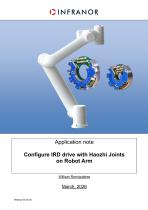
Application note Configure IRD drive with Haozhi Joints on Robot Arm William Romiguières
Open the catalog to page 1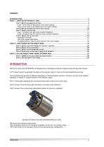
INTRODUCTION IRD servo drives from INFRANOR are designed to be embedded inside the Haozhi joints with high ratio reducer. A 2nd position sensor is generally mounted on the reducer output to improve the load positioning accuracy. The commissioning process is different depending on the joint position sensor’s structure: only the motor position feedback, or added 2nd position sensor on the reducer output. Part 1 of this paper describes the commissioning process of the joint in both cases. Part 2 concern the axis tuning when the joint is mounted on the robot arm. Part 3 concern the on-line tuning...
Open the catalog to page 2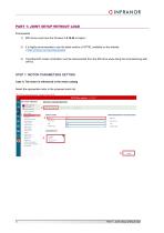
1) IRD drives must have the firmware 1.2.18.54 or higher; 2) It is highly recommended to use the latest version of OPTIO, available on the website ( https://infranor.com/en/downloads/) 3) The EtherCAT master (controller) must be disconnected from the IRD drive when doing the commissioning with OPTIO Select the appropriate motor in the proposed motor list. User position scaling Following errors Profile modes Position sensors Brake control Stop operation Position limits Modulo Digital inputs Digital outputs Sequences Digital cams Field bus configuration Process data configuration Seen red data...
Open the catalog to page 3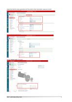
itant by Infranor SAS - Copyright © Infra OPTIO Drive Assistant vl .0.39.917 MOTOR CONFIGURATION MOTOR CATALOG NEW MOTOR ADVANCED Device information Power supply M otor config uration Controller Position sensors Brake control Position limits Modulo Digital inputs Digital outputs Sequences Fieldbus configuration Process data configuration MOTOR DETAILS General information Type complement |+| Position sensor ED Drive current loop [—1 Motor protection i current limit (A) rent limit (A) Set the reducer ratio of the joint. Power supply Motor Configuration Control!** Profile modes Position sensors...
Open the catalog to page 4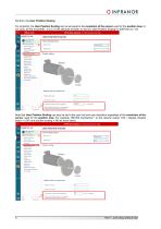
Set then, the User Position Scaling:For simplicity, the User Position Scaling can be set equal to the resolution of the sensor used for the position loop. Inour case, for the encoder#"!, it is a 21 bits absolute encoder, so we set “User Position Scaling” to 2097152 inc / rev. ■r'l Power supply Motor configuration Controller Profile modes Position sensors Brake control Stop operation Position limits Digital inputs Digital outputs Digital cams Fietdbus configuration Process data configuration Secured data Display factor | Position scaling Motor LoadReducer ratio for rotative axis Reducer ratio...
Open the catalog to page 5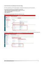
Case 2) The motor is not referenced in the motor catalog The motor parameters can be manually adjusted or calculated by using the drive's built-in procedures. The required motor data for the manual setup are listed below: - Motor position sensor specifications (BISS-C encoder parameters) - Motor current limits: rated current and peak current - Motor winding inductance - Motor speed limit Select the motor type and set the motor sensor parameters values Q OPTIQ Drive Assistant by Infranor SAS - Copyright © Infranor SAS 2025 OPTIO Drive Assistant vl .0.39.917 Device information j^owersuggl^^^^^...
Open the catalog to page 6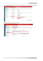
^ OPTIO Drive Assistant by Infranor SAS - Copyright © Infranor SAS 2025 — OPTIO Drive Assistant by Infranor SAS - Copyright © Infranor SAS 2026 Device information Power supply Motor configuration Controller User position scaling Following errors Profile modes Motor feedback Motor feedback sensor BiSS-C encoder #1 Note: The motor feedback can only be set in the motor configuration window Position sensors Brake control Stop operation Position limits Modulo Digital inputs Digital outputs Position loop feedback sensor selection Feedback type BiSS-C encoder #1 (Motor feedback) Sensor parameters Name...
Open the catalog to page 7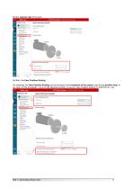
Set the reducer ratio of the joint. Set then, the User Position Scaling: For simplicity, the User Position Scaling can be set equal to the resolution of the sensor used for the position loop. In our case, for the encoder#"!, it is a 21 bits absolute encoder, so we set “User Position Scaling” to 2097152 inc / rev. Power supply Motor configuration . Controller_ Display factor flowing errors Profile modes Position sensors Brake control Stop operation Position limits Modulo Digital inputs Digital outputs Sequences Digital cams FieWbus configuration Process data configuration Secured data Motor Load...
Open the catalog to page 8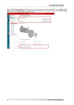
Following error* Prpfa* modes Position sensors Brake control Stop operation Position limits Digital inputs Digital outputs Digital cams Process data configuration Secured data LoadReducer ratio for rotative axis Reducer ratio input Reducer ratio output n3 One reducer output revolution represents Notr In case of reeftjeer ratio > 1 the scaling is between the reducer output and the load. 9 Part 1: Joint setup without load
Open the catalog to page 9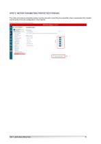
Process data Device information Power supply Motor configuration Controller User position scaling Following errors Profile modes Position sensors Brake control Stop operation Position limits Digital inputs Digital outputs Digital cams Fieldbus configuration Process data configuration Poles pairs number Phases order Feedback offset Reducer ratio input Reducer ratio output Part 1: Joint setup without load 10
Open the catalog to page 10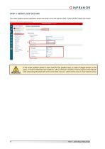
The motor position sensor parameter values have been set on the previous step. Check that the values are correct. |J OPTIO Drive Assistant by InfranorSAS- Copyright© lnfranorSAS2025 OPTIO Drive Assistant vl .0.39.917 ■ MY LAST PROJECT B Store parameters Device information _Power_su£|3l^^^^ MOTOR CONFIGURATION MOTOR CATALOG NEW MOTC 2 | ADVANCEI[T"| iHl Controller User position scaling Following errors Profile modes Position sensors Brake control Stop operation Position limits Modulo Digital inputs Digital outputs Sequences Fieldbus configuration Process data configuration Secured data MOTOR DETAILS...
Open the catalog to page 11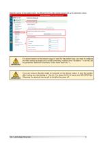
Position sensors Brake control Stop operation Position limits Digital inputs Digital outputs Digital cams Fieldbus configuration Process data configuration Secured data Motor feedback Motor feedback sensor BiSS-C encoder #1 Note: The motor feedback can only be set in the motor configuration window Position loop feedback sensor selection Feedback type Sensor parameters Clock frequency CRC length Encoder resolution (increments per revolution) Maximum revolutions SCD length without CRC If a second sensor on the reducer output is used for the position loop, you need to configure the motor sensor...
Open the catalog to page 12All Infranor Group catalogs and technical brochures
 XtrapulsPac_EN
4 Pages
 SMTBSi-2Tz_en_2.1
43 Pages
 PacSimBox_d_1
1 Page
 Pac-SF01_flyer_en_18.02
4 Pages
 Pac_User_1.2.1.218
253 Pages
 Pac_Templates_en_1.9
27 Pages
 Pac_STO_Installation_en_2.2
13 Pages
 Pac_SF01_operating_en_1.6
63 Pages
 Pac_SF01_EN
4 Pages
 Pac_Installation_en_2.23
82 Pages
 Pac_flyer_en_17.12
4 Pages
 Option_CT_EMF
6 Pages
 MOVINOR_LH055_LH086_LH097_LH142
23 Pages
 ma_series
6 Pages
 GemSafeTorqueOff_en_1.1
12 Pages
 CD1pm_e_1.2(old)
18 Pages
 CD1pInst_e_7.2(old)
35 Pages
 CD1kInst_e_4.1(old)
40 Pages
 CD1k_CANopenProtocol_e_1.3(old)
86 Pages
 CD1a_e_7.1(old)
45 Pages
 Catalogue gamme SMT-BD1
11 Pages
 BM20A(F)v3_0
20 Pages
 BM20A(D)v3_0
20 Pages
 BF400(GB)v2_2
21 Pages
 BF400(D)v2_2
21 Pages
 BF230(GB)v2_0
23 Pages
 BF230(F)v2_0
23 Pages
 BD2m_e_2.2
69 Pages
 BD2m(GB)2.0
70 Pages
 BD2_e_3.2
53 Pages
 BD2(GB)3.1
53 Pages
 BD2(D)3.1
54 Pages
 Movinor_LH_e
4 Pages
 ma_series
6 Pages
 BD1t(GB)3.1
81 Pages
 BD1t(F)3.0
85 Pages
 BD1pInst(GB)3.0
25 Pages
 BD1pInst(F)3.0
23 Pages
 BD1pInst(D)3.0
24 Pages
 BD1pCD1pUse_e_2.4
57 Pages
 BD1m(GB)5.0
58 Pages
 BD1m(F)5.0
57 Pages
 BD1m(D)v3_3
64 Pages
 BD1k(GB)2.1
35 Pages
 BD1k(F)2.1
36 Pages
 BD1j(GB)v2_41
19 Pages
 BD1j(F)v2_4
21 Pages
 BD1i(GB)v2_21
23 Pages
 BD1i(F)v2_2
27 Pages
 BD1h(F)3.0
65 Pages
 BD1h(D)3.0
59 Pages
 BD1g(GB)v3_0
28 Pages
 BD1g(F)v3_0
28 Pages
 BD1a400(GB)v2_3
43 Pages
 BD1a400(F)v2_3
44 Pages
 BD1a400(D)v2_3
45 Pages
 BD1(GB)7.1_noPW
45 Pages
 BD1(GB)7.1
45 Pages
 BD1(F)7.1_noPW
47 Pages
 BD1(F)7.1
47 Pages
 BD1(D)7.1
45 Pages
 BD1 Katalog
11 Pages
 Easy_User_5.0.1.60.2
190 Pages
 01ma_smv_e_01953
40 Pages
 PacHP-SF_Flyer_en_23.06
4 Pages
 IRD_User_Manual_en_1.2.XX.54.rev_b
216 Pages
 PacHP_User_en_1.2.8.100.b
280 Pages
 PacHP_SF02_operating_en_1.6
103 Pages
 PacHP_SF01_operating_en_2.0
63 Pages
 PacHP_Installation_en_2.9
91 Pages
 PacHP_Series_Brochure
8 Pages
 PacHP_Flyer_us_20.10
4 Pages
 IRD_Installation_en_1.5
42 Pages
 Easy_STO_en_1.4
14 Pages
 Easy_DB_STO_en_1.2
14 Pages
 Easy_DB_Installation_en_1.4
36 Pages
 CD1pmUser_en_4.2
55 Pages
 CD1pmInst_en_8.15
40 Pages
 CD1k_CANopenProtocol_en_2.10.1.1
108 Pages
 CD1pm_ProfibusProtocol_en_1.5
50 Pages
 CD1kUser_en_2.3
26 Pages
 CD1a_en_8.17
62 Pages
 CD1kInst_en_5.16
46 Pages
 CD1_STO_en_1.8
16 Pages
 CD1_flyer_en_14.09
4 Pages
 Braking_Resistors_en_1.5
10 Pages
 XtracontrolDC2_EN
4 Pages
 Flyer_VisiTouchCNC_EN_V1.1-1
2 Pages
 XtraforsWashdown_EN-2024
2 Pages
 DataSheet_CybIO_CNC_V1.0
6 Pages
 XtraforsPrime_EN-2024
2 Pages
 XtraforsMSS_EN
4 Pages
 XtraforsMSA_EN_2024
2 Pages
 XtraforsEx_EN-2024
2 Pages
 XtraforsBR_EN-2024
2 Pages
 XtraforsBL_EN-2024
2 Pages
 XtraforsBC-ed01-vs3
4 Pages
 Manual_XtraforsPrime
46 Pages
 Drawing_1
1 Page
 Datasheet_MSS
5 Pages
 Datasheet_2
2 Pages
 Datasheet_1
4 Pages
 BLSBLT_series
2 Pages
 BL220221
2 Pages
 BL270
BL2702 Pages
 BL190
BL1902 Pages
 bl100_series
6 Pages
 bl40_series
6 Pages
 BL30
BL302 Pages
 2019-01_XtraforsFP-DSL_FR
4 Pages
 Movinor_T_EN
4 Pages
 Movinor_N_EN
4 Pages
 Movinor_Low_Voltage_EN
4 Pages
 Manual Movinor T 03-2026
46 Pages
 Manual Movinor N 03-2026
63 Pages
 XtrapulsEasy™ AC servo-drive
4 Pages
 XtrapulsCD1 AC servo-drives
4 Pages
 CybIO
CybIO6 Pages
 AC SERVOMOTORS
2 Pages
 Movinor® N AC Servomotors
4 Pages





Archived catalogs
 AN_CD1ak_AbsoluteEncoder_en_2.0
10 Pages
 AN_CD1ak_SinCosTracks_e_1.0
7 Pages
 AN_CD1pm_AbsoluteEncoder_en_2.0
10 Pages
 AN_CD1pm_SinCosTracks_e_1.0
7 Pages
 AN_DC_bus_interfacing_en_1.3
5 Pages
 CD1_EC_conformity_24.05
1 Page
 CD1_STO_conformity_19.02
2 Pages
 EtherCAT Interface_en_1.3
20 Pages
 Easy_EC_Conformity_24_10
1 Page
 GDPS_EC_conformity_24.07
1 Page
 IRD_EC_Conformity_25.03
1 Page
 PacHP_TÜV_certificate_25.07
2 Pages
 BD1c(F)v2_01
19 Pages
 BD1c(GB)v2_01
19 Pages
 BD1d(F)v2_01
25 Pages
 BD1d(GB)v2_01
25 Pages
 BD1e(F)v2_01
22 Pages
 BD1f(F)v2_01
17 Pages
 BD1f(GB)v2_01
18 Pages
 Pac_EC_conformity_25.04
1 Page




















