- Catalogs
- Infranor Group
- GemSafeTorqueOff_en_1.1


GemSafeTorqueOff_en_1.1

GemSafeTorqueOff_en_1.1
The GD1 Safe Torque Off (STO) Manual provides guidelines for servo drives used with AC brushless sinusoidal servo motors. The STO function prevents motor rotation by ensuring no power is applied, complying with EN 61800-5-2 standards. It is essential for preventing unexpected motor start-ups and may require additional measures like mechanical brakes in certain situations.
- Functional Diagram: The STO function stops motor shaft movement by removing IGBT command supply and PWM signals, incorporating safety channels and fault monitoring.
- Command System Conception: STO integration requires a risk analysis, with safety instructions to avoid short-circuits and ensure proper installation in an IP54 protected control cabinet.
- STO Connection: Details include connector specifications, input/output requirements, and voltage levels, using optocoupled inputs in negative logic.
- Timings: Specific activation and release response times are defined, with monitoring for channel incoherence to lock channels safely if needed.
- Performance Level: The STO function meets category 3/PLd of EN ISO 13849-1:2006, equivalent to SIL2.
- Periodic Inspection Routines: Annual checks ensure all safety subsystems are operational, with a detailed inspection process provided.
- Residual Risk: There is a potential risk of motor shaft rotation due to a short-circuit between power transistors.
Examples for integrating the STO function include a stop category 0 setup per EN 60204-1, suitable for low inertia or high resistive torque applications.
The document details configuration and connection for a multiaxis system using a GD1 servodrive, specifying power supply requirements of a 230 Vac single-phase auxiliary supply and a brake supply. It supports 230 V and 400 V configurations with power capacities of less than 4 kW for 230 V or less than 7 kW for 400 V.
Before activating the STO function, disable motor control. Use digital input IN1 to disable PWM control, with a light on the STO_OUT output indicating drive state. An example stop category 1 procedure per EN 60204-1, compliant with EN13849-1 category 3, involves using a PILZ safety relay to decelerate the servodrive via the ENABLE signal, then activating the STO function after a 0.5-second delay.
The GD1 range complies with EN954-1 and EN 13849-1 standards, with the STO function being safe according to EN13849-1 category 3.
Set up servodrive behavior on ENABLE signal activation in the appropriate mode, such as speed ramp deceleration, before any stop procedure. Shielded cables are unnecessary as the PILZ safety relay detects short-circuits.
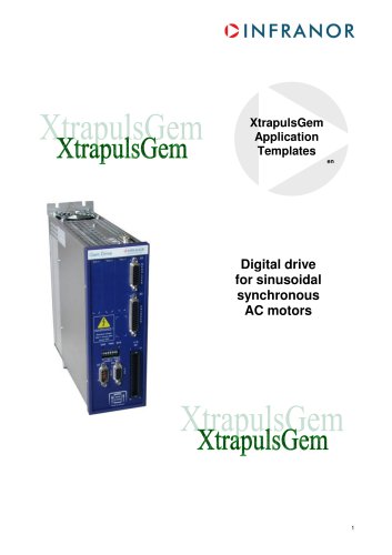
The GD1 servodrive order code includes specifications for voltage (230 or 400 Vac), peak current, power supply, integrated braking resistor, safety features, and extension slots for additional interfaces like Profibus DP, additional input/output, Encoder Output, and Ethercat.
Catalog excerpts
Gem Drive Safe Torque Off Manual
Open the catalog to page 1
WARNING This is a general manual describing a series of servo drives having output capability suitable for driving AC brushless sinusoidal servo motors. Please see GD1 User Guide for the operation of the drive (commissioning, configuration, …). Instructions for storage, use after storage, commissioning as well as all technical details require the MANDATORY reading of the manual before getting the drives operational. Maintenance procedures should be attempted only by highly skilled technicians having good knowledge of electronics and servo systems with variable speed (EN 60204-1 standard) and...
Open the catalog to page 2
CINFRANOR SERVO DRIVES & MOTION CONTROL 3.1 - Example 1: Stop category 0 according to EN 60204-1 complying with EN13849-1 cat. 3... 8 3.2 - Example 2: Stop category 1 according to EN 60204-1 complying with EN13849-1 cat. 3 ... 9
Open the catalog to page 3
Chapter 1 – General description Safe Torque Off (STO) definition according to the EN 61800-5-2 standard: "Power, that can cause the rotation of a motor (or displacement in the case of a linear motor), is not applied to the motor. The drive will not provide energy to the motor which can generate torque (or force in the case of a linear motor)". The STO function corresponds to an uncontrolled stopping in accordance with the stop category 0 of the EN 60204-1 standard. The STO function may be used where power removal is required to prevent an unexpected start-up. In circumstances where external influences...
Open the catalog to page 4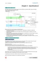
Chapter 2 – Specifications 2.1 – FUNCTIONAL DIAGRAM The "Safe Torque Off" function allows to keep the motor shaft free by avoiding the IGBT module commutation. This is achieved by means of two techniques: - IGBT command supply removal, - PWM removal. GEM DRIVE DSP POWER BOARD IGBT Module Drivers STO_OUT Different parts of the functional diagram are described below: • The green part is the first channel of the safety function. PWM signals are disabled by inhibiting the optocouplers commutation. • The blue part is the second channel of the safety function. IGBT gate signals are disabled by the...
Open the catalog to page 5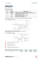
CINFRANOR 2.2.2 - STO CONNECTION 2.2.2.1 - X2 Connector Weidmuller D 32 pins male Section: 0.25 mm2 (AWG22) During the installation, take care to avoid proximity between any STO signal and high potential. These optocoupled inputs operate in negative logic. The input voltage corresponding to level 1 must be between 18 V and 30 V. External supply +24 V (18 V < U < 30 V) Maximum voltage drop: 2 V Protection against overload Available output current per output (mA)
Open the catalog to page 6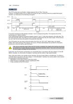
2.2.3 – TIMINGS The STO function has an activation / release response time of 15ms / 2ms max. However, an additional delay of 6,5 ms after STO inputs are high is necessary before the enable/inhibit signal activation, as mentioned on the following chronogram: STO1/ t≤50ms Drive state 2ms Safe : Warning STO active displayed 0x3024,0.bit0 A functional incoherence state between channels 1 and 2 is allowed during 50ms. The response time of the monitoring part is 100ms to 200ms. If the monitoring part detects incoherence between channel 1 and 2, it locks both channels in the safe state. The STO fault...
Open the catalog to page 7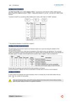
CINFRANOR 2.2.4 - Performance level The Safe Torque Off function fulfills category 3 /PLd (1) requirements of the EN ISO 13849-1:2006 standard. PLd corresponds to SIL2 according to "Table 4 - Relationship between PL and SIL" of the EN ISO 13849-1:2006 standard. To achieve overall PL by combining safety related parts in series, refer to §6.3 of 13849-1 standard: At each step, the operator must verify that the motor provides or not torque, If the drive behavior is different from the one described in the table above, the drive must be replaced. In case of short-circuit between two power transistors,...
Open the catalog to page 8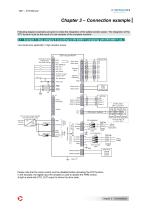
GDI - STO Manual SERVO DRIVES & MOTION CONTROL Following diagram examples are given to make the integration of the safety function easier. The integration of the STO function must be the result of a risk analysis of the complete machine. Low inertia axis application / high resistive torque GD1-uuu/cc/PS-R Example of inputs configuration See User manual 24 V Ext. if logic outputs used Motor brake + Motor brake - GND Motor U phase Motor V phase Motor W phase MOTOR GND Phase 1 Phase 2 Phase 3 L1 phase L2 phase L3 phase GND Total power of the application < 4 kW in 230 V or < 7 kW in 400 V Braking...
Open the catalog to page 9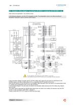
3.2 – Example 2: Stop category 1 according to EN 60204-1 complying with EN13849-1 cat. 3 High inertia axis application / low resistive torque In the following diagram, only the STO integration is safe. The deceleration ramp is not safe according to EN13849-1 because it uses a common drive function. Motor temp. Motor temp. Example of inputs 32 AOK+ configuration 31 AOKSee User manual 1 IN1 (ENABLE) 2 IN2 (FC+) 3 IN3 (FC-) 4 IN4 (Index) 19 24 V Ext. if logic outputs used 20 Ext. reference 24V Resolver signal Resolver reference Motor brake - 24 Vdc power supply isolated from the 230 Vac mains AC...
Open the catalog to page 10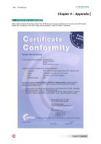
After a deep analysis of the GDI range, the CETIM (French Industrial and Mechanical Technical Center) third-party attests the compliance of the GD1 range with the EN954-1 and EN 13849-1 standards: Gf i c-cd:M[ ilon Vi lw Number A526 04 09 65 02 To the request of the Company : INFAANOR SAS Avenue Jean Moulin BP 142 A technical file and a sample of the following equipment: Designation : GEM DRIVE Series [with safety function STO : Safe torque off) Brand : INFRANOFI servo drives and motion control Type : GDI-uuu/cc-SI (SI : STO integrated). Have been examined by Daniei RENAULT, CETIM PlD - Machines...
Open the catalog to page 11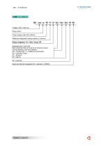
4.2 – ORDER CODE GD1 – uuu / cc – PS – R – SI – Ex1 – Ex2 – Ex3 – 00 - RS Voltage: 230 or 400 Vac Peak current Power supply inside (00: without) Additional integrated braking resistor (0: without) Safety integrated: S1 = Safe Torque Off Extensions Ex1, Ex2, Ex3: Each extension slot can receive an extension board. Can be selected: One bus interface: PR = Profibus DP, I1 = additional input/output, EO = Encoder Output ET = Ethercat 00 = without 00 = reserved Serial link RS-422 integrated (00 = standard = RS232)
Open the catalog to page 12All Infranor Group catalogs and technical brochures
 XtrapulsPac_EN
4 Pages
 XtrapulsGemTemplates_e_1.4
21 Pages
 XtrapulsGem_User_Manual_v1.2.0.64
199 Pages
 XtrapulsGem_Inst_e_2.1
42 Pages
 XtrapulsGem_Inst_e_2.0
42 Pages
 SMTBSi-2Tz_en_2.1
43 Pages
 smt-100
32 Pages
 PacSimBox_d_1
1 Page
 Pac-SF01_flyer_en_18.02
4 Pages
 Pac_User_1.2.1.218
253 Pages
 Pac_Templates_en_1.9
27 Pages
 Pac_STO_Installation_en_2.2
13 Pages
 Pac_SF01_operating_en_1.6
63 Pages
 Pac_SF01_EN
4 Pages
 Pac_Installation_en_2.23
82 Pages
 Pac_flyer_en_17.12
4 Pages
 Option_CT_EMF
6 Pages
 MOVINOR_LH055_LH086_LH097_LH142
23 Pages
 ma_series
6 Pages
 GemProgramming_e_1.1
47 Pages
 GDPS_old_version_1.1_1
11 Pages
 CD1pm_e_1.2(old)
18 Pages
 CD1pInst_e_7.2(old)
35 Pages
 CD1kInst_e_4.1(old)
40 Pages
 CD1k_CANopenProtocol_e_1.3(old)
86 Pages
 CD1a_e_7.1(old)
45 Pages
 Catalogue gamme SMT-BD1
11 Pages
 BM20A(F)v3_0
20 Pages
 BM20A(D)v3_0
20 Pages
 BF400(GB)v2_2
21 Pages
 BF400(D)v2_2
21 Pages
 BF230(GB)v2_0
23 Pages
 BF230(F)v2_0
23 Pages
 BD2m_e_2.2
69 Pages
 BD2m(GB)2.0
70 Pages
 BD2_e_3.2
53 Pages
 BD2(GB)3.1
53 Pages
 BD2(D)3.1
54 Pages
 Movinor_LH_e
4 Pages
 ma_series
6 Pages
 BD1t(GB)3.1
81 Pages
 BD1t(F)3.0
85 Pages
 BD1pInst(GB)3.0
25 Pages
 BD1pInst(F)3.0
23 Pages
 BD1pInst(D)3.0
24 Pages
 BD1pCD1pUse_e_2.4
57 Pages
 BD1m(GB)5.0
58 Pages
 BD1m(F)5.0
57 Pages
 BD1m(D)v3_3
64 Pages
 BD1k(GB)2.1
35 Pages
 BD1k(F)2.1
36 Pages
 BD1j(GB)v2_41
19 Pages
 BD1j(F)v2_4
21 Pages
 BD1i(GB)v2_21
23 Pages
 BD1i(F)v2_2
27 Pages
 BD1h(F)3.0
65 Pages
 BD1h(D)3.0
59 Pages
 BD1g(GB)v3_0
28 Pages
 BD1g(F)v3_0
28 Pages
 BD1a400(GB)v2_3
43 Pages
 BD1a400(F)v2_3
44 Pages
 BD1a400(D)v2_3
45 Pages
 BD1(GB)7.1_noPW
45 Pages
 BD1(GB)7.1
45 Pages
 BD1(F)7.1_noPW
47 Pages
 BD1(F)7.1
47 Pages
 BD1(D)7.1
45 Pages
 BD1 Katalog
11 Pages
 08ma_ms_e_01700
20 Pages
 Easy_User_5.0.1.60.2
190 Pages
 08ma_mrm_em_01575
20 Pages
 01ma_smv_e_01953
40 Pages
 PacHP-SF_Flyer_en_23.06
4 Pages
 IRD_User_Manual_en_1.2.XX.54.rev_b
216 Pages
 PacHP_User_en_1.2.8.100.b
280 Pages
 PacHP_SF02_operating_en_1.6
103 Pages
 PacHP_SF01_operating_en_2.0
63 Pages
 PacHP_Installation_en_2.9
91 Pages
 PacHP_Series_Brochure
8 Pages
 PacHP_Flyer_us_20.10
4 Pages
 IRD_Installation_en_1.5
42 Pages
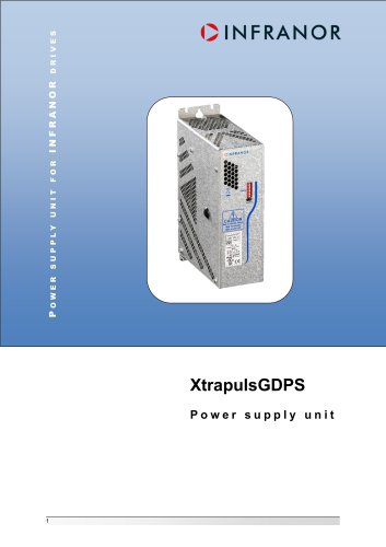 GDPS_Installation_en_4.4
18 Pages
 Easy_STO_en_1.4
14 Pages
 Easy_DB_STO_en_1.2
14 Pages
 Easy_DB_Installation_en_1.4
36 Pages
 CD1pmUser_en_4.2
55 Pages
 CD1pmInst_en_8.15
40 Pages
 CD1k_CANopenProtocol_en_2.10.1.1
108 Pages
 CD1pm_ProfibusProtocol_en_1.5
50 Pages
 CD1kUser_en_2.3
26 Pages
 CD1a_en_8.17
62 Pages
 CD1kInst_en_5.16
46 Pages
 CD1_STO_en_1.8
16 Pages
 CD1_flyer_en_14.09
4 Pages
 Braking_Resistors_en_1.5
10 Pages
 XtracontrolDC2_EN
4 Pages
 Flyer_VisiTouchCNC_EN_V1.1-1
2 Pages
 XtraforsWashdown_EN-2024
2 Pages
 DataSheet_CybIO_CNC_V1.0
6 Pages
 XtraforsPrime_EN-2024
2 Pages
 XtraforsMSS_EN
4 Pages
 XtraforsMSA_EN_2024
2 Pages
 XtraforsEx_EN-2024
2 Pages
 XtraforsBR_EN-2024
2 Pages
 XtraforsBL_EN-2024
2 Pages
 XtraforsBC-ed01-vs3
4 Pages
 Manual_XtraforsPrime
46 Pages
 Drawing_1
1 Page
 Datasheet_MSS
5 Pages
 Datasheet_2
2 Pages
 Datasheet_1
4 Pages
 BLSBLT_series
2 Pages
 BL220221
2 Pages
 BL270
BL2702 Pages
 BL190
BL1902 Pages
 bl100_series
6 Pages
 bl40_series
6 Pages
 BL30
BL302 Pages
 2019-01_XtraforsFP-DSL_FR
4 Pages
 Movinor_T_EN
4 Pages
 Movinor_N_EN
4 Pages
 Movinor_Low_Voltage_EN
4 Pages
 Manual Movinor T 03-2026
46 Pages
 Manual Movinor N 03-2026
63 Pages
 XtrapulsEasy™ AC servo-drive
4 Pages
 XtrapulsCD1 AC servo-drives
4 Pages
 CybIO
CybIO6 Pages
 AC SERVOMOTORS
2 Pages
 Movinor® N AC Servomotors
4 Pages






Archived catalogs
 AN_CD1ak_AbsoluteEncoder_en_2.0
10 Pages
 AN_CD1ak_SinCosTracks_e_1.0
7 Pages
 AN_CD1pm_AbsoluteEncoder_en_2.0
10 Pages
 AN_CD1pm_SinCosTracks_e_1.0
7 Pages
 AN_DC_bus_interfacing_en_1.3
5 Pages
 CD1_EC_conformity_24.05
1 Page
 CD1_STO_conformity_19.02
2 Pages
 EtherCAT Interface_en_1.3
20 Pages
 Easy_EC_Conformity_24_10
1 Page
 GDPS_EC_conformity_24.07
1 Page
 IRD_EC_Conformity_25.03
1 Page
 PacHP_TÜV_certificate_25.07
2 Pages
 BD1c(F)v2_01
19 Pages
 BD1c(GB)v2_01
19 Pages
 BD1d(F)v2_01
25 Pages
 BD1d(GB)v2_01
25 Pages
 BD1e(F)v2_01
22 Pages
 BD1f(F)v2_01
17 Pages
 BD1f(GB)v2_01
18 Pages
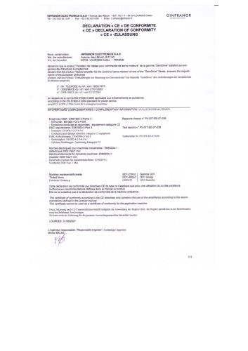 CE_conformity_Gem
1 Page
 Pac_EC_conformity_25.04
1 Page
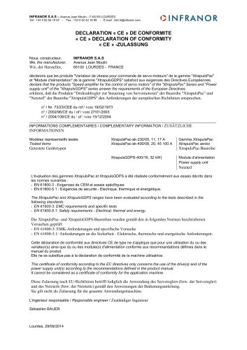 Pac_GDPS_CEconformity
1 Page
![SMT100D_e_1.01[1]](https://img.directindustry.com/pdf/repository_di/4620720/smt100d-e-101-1-1141223_1mg.jpg) SMT100D_e_1.01[1]
SMT100D_e_1.01[1]40 Pages
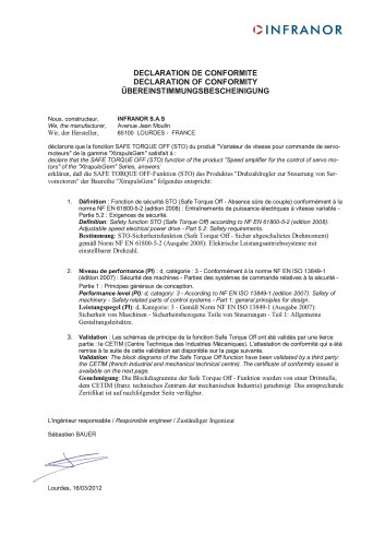 STO_declaration_Gem
2 Pages