- Catalogs
- Infranor Group
- GDPS_Installation_en_4.4


- Products
- Catalogs
- News & Trends
- Exhibitions
GDPS_Installation_en_4.4
1 /18Pages
GDPS_Installation_en_4.4
1 /18Pages
Catalog excerpts
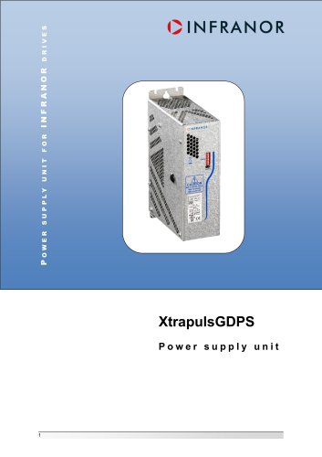
GDPS installation guide XtrapulsGDPS Power supply unit
Open the catalog to page 1
GDPS installation guide This is a general manual describing a series of power supplies having output capability suitable for powering servo drives. Instructions for storage, use after storage, commissioning as well as all technical details require the MANDATORY reading of the manual before getting the drives operational. Maintenance procedures should be attempted only by highly skilled technicians having good knowledge of electronics and servo systems with variable speed (EN 60204-1 standard) and using proper test equipment. The conformity with the standards and the "CE" approval is only valid...
Open the catalog to page 2
GDPS installation guide All electrical industrial automatisms which lifetime is coming to its end are Waste Electronic and Electrical Equipment (WEEE) according to article R543-172 of the French Environmental Code. WASTE DISPOSAL This symbol indicates that INFRANOR devices shall be eliminated by selective disposal and not with household waste. WEEE classification of the INFRANOR products Category 9: Monitoring and control instruments In accordance with the Decree nr. 2012-617 of May 2nd, 2012 which specifies the provisions related to the professional EEE manufacturers' obligations, INFRANOR...
Open the catalog to page 3
GDPS installation guide
Open the catalog to page 4
GDPS installation guide QINFRANOR 1.1.1 -General description The external XtrapulsGDPS-400/xx power supply unit is the multi-axis power supply intended for use with the XtrapulsPac and XtrapulsPacHP servo drives. For the various configurations, see XtrapulsPac and XtrapulsPacHP Installation manuals. The XtrapulsGDPS -400/xx power supply unit operates within a wide voltage range between 230 and 480 Vac. Consequently, the output power will depend on the input voltage. The specified power values are given for a maximum voltage of 480 Vac. 1.1.2 -Reference to directives and standards C€ Harmonized...
Open the catalog to page 5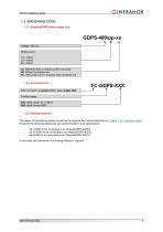
GDPS installation guide 1.2 -ORDERING CODE 1.2.1 -XtrapulsGDPS power supply unit GDPS-400/pp-xx Voltage: 400 VAC Rated power: 16 = 16kW 32 = 32kW 64 = 64kW xx: Delivered with or without power connector 00: Without connector set FC: With power (X1) + auxiliary (X2) connector set 1.2.2 -Connectors kit With connector set power (X1) + aux. supply (X2) Product range 403: rated power 16 or 32kW 406: rated power 64kW 1.2.3 -Braking resistors The choice of the braking resistor should be the result of the method described in Chapter 1.5.3: Braking system. However, the following references are recommended...
Open the catalog to page 6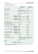
GDPS installation guide OINFRANOR For special applications, the input voltage range can be extended to 230 Vac - 480 Vac (see chapter 2.4 for reducing the undervoltage threshold to 100 Vdc).
Open the catalog to page 7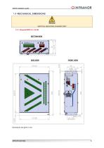
GDPS installation guide Warning VERTICAL MOUNTING IS MANDATORY 1.4.1 -XtrapulsGDPS 16 / 32 kW BOTTOM VIEW SIDE VIEW FRONT VIEW
Open the catalog to page 8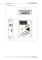
GDPS installation guide 1.4.2 -XtrapulsGDPS 64 kW
Open the catalog to page 9
GDPS installation guide 1.5 -SIZING OF THE POWER SUPPLY 1.5.1 -Continuous power For a reliable and safe operation of the installation, the continuous average power needs to be evaluated for all axes. Various ways to proceed for evaluating the continuous power of a machine are listed below: Accurate method: The power can be calculated by the absolute value average of the mechanical power for each axis. Torque value in Nm (positive when the speed increases) Speed value in rad/s Duration of the deceleration or acceleration phase Period of the whole cycle Simplified method 1: If the continuous average...
Open the catalog to page 10
GDPS installation guide Simplified method 2: If the continuous average power cannot be evaluated by the "accurate method", it may be convenient to define a service ratio (KS) for each drive. In this case, the average power can be evaluated by means of following formula: Prated.axis.n = 3 U I rated.axis.n 1.5.2 -Peak power The sum of the electrical power of all axes must not exceed the power ability of the XtrapulsGDPS supply unit at any moment. The maximum power of a servo-axis is generally reached at the end of the acceleration phase. 1.5.3 -Braking system The braking I²t function defines...
Open the catalog to page 11
GDPS installation guide Choice of the ohmic value With: RMIN: Minimum braking resistor value in Ohm according to section "Main technical data". UBRAKING: Triggering threshold of the braking system in V. RBRAKING: Braking resistor in . Maximum of all PELEC calculated for all motors and for all deceleration phases in W. Average power The required average power must be calculated to correctly choose the size of the braking resistor and to take into account the heat dissipation effect into the near environment. PELEC (n, p) TDEC (n, p) TCYCLE Power managed by the drive axis n during the deceleration...
Open the catalog to page 12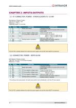
GDPS installation guide QINFRANOR Manufacturer: Phoenix Contact Type: PC 5/ 7-STCL1-7.62 Reference: 1778117 Tightening torque: 0.7 to 0.8 Nm *) According to the actual power, the total cross section can be distributed on all four DC bus outputs
Open the catalog to page 13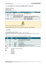
GDPS installation guide OINFRANOR Manufacturer: Weidmuller Type: BLZP 5.08 / 04 / 180 Reference: 194360 Tightening torque: 0.4 to 0.5 Nm X No influence on the status described — — regular blink — — three flashes
Open the catalog to page 14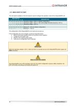
GDPS installation guide 2.5 -MINI-SWITCH SW1 The mini-switch available on the front panel is used to configure the operation mode of the XtrapulsGDPS unit: MINI-SWITCH 1 2 3 4 5 6 0 0 0 0 X X 1 1 0 0 X X 1 1 1 1 X X DESCRIPTION 7 8 X X Operating voltage = 400 VAC (default configuration) X X Operating voltage = 400 VAC with undervoltage threshold reduced to 100 VDC X X Operating voltage = 230 VAC Braking I²t = 200 ms (default configuration) Braking I²t = 100 ms The configuration of the XtrapulsGDPS unit is read only at power up. If the configuration has to be changed, proceed as described below:...
Open the catalog to page 15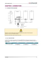
GDPS installation guide QINFRANOR Power relay remote control 24 V Xtrapuls drive Q1: Circuit breaker type D 3.2 -UL FUSE RATING In order to be UL compliant, the protection of the XtrapulsGDPS-400/xx multi-axis power supply unit must be achieve by a class J fuse. Suitable for use on a circuit of delivering not more 5000Arms symmetrical amperes at a voltage of 480V.
Open the catalog to page 16All Infranor Group catalogs and technical brochures
 XtrapulsPac_EN
4 Pages
 XtrapulsGemTemplates_e_1.4
21 Pages
 XtrapulsGem_User_Manual_v1.2.0.64
199 Pages
 XtrapulsGem_Inst_e_2.1
42 Pages
 XtrapulsGem_Inst_e_2.0
42 Pages
 STO_declaration_Gem
2 Pages
 SMTBSi-2Tz_en_2.1
43 Pages
![SMT100D_e_1.01[1]](https://img.directindustry.com/pdf/repository_di/4620720/smt100d-e-101-1-1141223_1mg.jpg) SMT100D_e_1.01[1]
SMT100D_e_1.01[1]40 Pages
 smt-100
32 Pages
 PacSimBox_e
1 Page
 PacSimBox_d_1
1 Page
 Pac-SF01_flyer_en_18.02
4 Pages
 Pac_User_1.2.1.218
253 Pages
 Pac_Templates_en_1.9
27 Pages
 Pac_STO_Installation_en_2.2
13 Pages
 Pac_SF01_operating_en_1.6
63 Pages
 Pac_SF01_EN
4 Pages
 Pac_Installation_en_2.23
82 Pages
 Pac_GDPS_CEconformity
1 Page
 Pac_flyer_en_17.12
4 Pages
 Pac_EC_conformity_25.04
1 Page
 Option_CT_EMF
6 Pages
 MOVINOR_LH055_LH086_LH097_LH142
23 Pages
 ma_series
6 Pages
 GemSafeTorqueOff_en_1.1
12 Pages
 GemProgramming_e_1.1
47 Pages
 GDPS_old_version_1.1_1
11 Pages
 CE_conformity_Gem
1 Page
 CD1pm_e_1.2(old)
18 Pages
 CD1pInst_e_7.2(old)
35 Pages
 CD1kInst_e_4.1(old)
40 Pages
 CD1k_CANopenProtocol_e_1.3(old)
86 Pages
 CD1a_e_7.1(old)
45 Pages
 Catalogue gamme SMT-BD1
11 Pages
 BM20A(F)v3_0
20 Pages
 BM20A(D)v3_0
20 Pages
 BF400(GB)v2_2
21 Pages
 BF400(D)v2_2
21 Pages
 BF230(GB)v2_0
23 Pages
 BF230(F)v2_0
23 Pages
 BD2m_e_2.2
69 Pages
 BD2m(GB)2.0
70 Pages
 BD2_e_3.2
53 Pages
 BD2(GB)3.1
53 Pages
 BD2(D)3.1
54 Pages
 Movinor_LH_e
4 Pages
 ma_series
6 Pages
 BD1t(GB)3.1
81 Pages
 BD1t(F)3.0
85 Pages
 BD1pInst(GB)3.0
25 Pages
 BD1pInst(F)3.0
23 Pages
 BD1pInst(D)3.0
24 Pages
 BD1pCD1pUse_e_2.4
57 Pages
 BD1m(GB)5.0
58 Pages
 BD1m(F)5.0
57 Pages
 BD1m(D)v3_3
64 Pages
 BD1k(GB)2.1
35 Pages
 BD1k(F)2.1
36 Pages
 BD1j(GB)v2_41
19 Pages
 BD1j(F)v2_4
21 Pages
 BD1i(GB)v2_21
23 Pages
 BD1i(F)v2_2
27 Pages
 BD1h(F)3.0
65 Pages
 BD1h(D)3.0
59 Pages
 BD1g(GB)v3_0
28 Pages
 BD1g(F)v3_0
28 Pages
 BD1f(GB)v2_01
18 Pages
 BD1f(F)v2_01
17 Pages
 BD1e(F)v2_01
22 Pages
 BD1d(GB)v2_01
25 Pages
 BD1d(F)v2_01
25 Pages
 BD1c(GB)v2_01
19 Pages
 BD1c(F)v2_01
19 Pages
 BD1a400(GB)v2_3
43 Pages
 BD1a400(F)v2_3
44 Pages
 BD1a400(D)v2_3
45 Pages
 BD1(GB)7.1_noPW
45 Pages
 BD1(GB)7.1
45 Pages
 BD1(F)7.1_noPW
47 Pages
 BD1(F)7.1
47 Pages
 BD1(D)7.1
45 Pages
 BD1 Katalog
11 Pages
 08ma_ms_e_01700
20 Pages
 Easy_User_5.0.1.60.2
190 Pages
 08ma_mrm_em_01575
20 Pages
 01ma_smv_e_01953
40 Pages
 PacHP-SF_Flyer_en_23.06
4 Pages
 IRD_User_Manual_en_1.2.XX.54.rev_b
216 Pages
 PacHP_User_en_1.2.8.100.b
280 Pages
 PacHP_TÜV_certificate_25.07
2 Pages
 PacHP_SF02_operating_en_1.6
103 Pages
 PacHP_SF01_operating_en_2.0
63 Pages
 PacHP_Installation_en_2.9
91 Pages
 PacHP_Series_Brochure
8 Pages
 PacHP_Flyer_us_20.10
4 Pages
 IRD_Installation_en_1.5
42 Pages
 IRD_EC_Conformity_25.03
1 Page
 EtherCAT Interface_en_1.3
20 Pages
 GDPS_EC_conformity_24.07
1 Page
 Easy_STO_en_1.4
14 Pages
 Easy_EC_Conformity_24_10
1 Page
 Easy_DB_STO_en_1.2
14 Pages
 Easy_DB_Installation_en_1.4
36 Pages
 CD1pmUser_en_4.2
55 Pages
 CD1pmInst_en_8.15
40 Pages
 CD1k_CANopenProtocol_en_2.10.1.1
108 Pages
 CD1pm_ProfibusProtocol_en_1.5
50 Pages
 CD1kUser_en_2.3
26 Pages
 CD1a_en_8.17
62 Pages
 CD1kInst_en_5.16
46 Pages
 CD1_STO_en_1.8
16 Pages
 CD1_STO_conformity_19.02
2 Pages
 CD1_flyer_en_14.09
4 Pages
 CD1_EC_conformity_24.05
1 Page
 Braking_Resistors_en_1.5
10 Pages
 AN_DC_bus_interfacing_en_1.3
5 Pages
 AN_CD1pm_SinCosTracks_e_1.0
7 Pages
 AN_CD1pm_AbsoluteEncoder_en_2.0
10 Pages
 AN_CD1ak_SinCosTracks_e_1.0
7 Pages
 AN_CD1ak_AbsoluteEncoder_en_2.0
10 Pages
 XtracontrolDC2_EN
4 Pages
 Flyer_VisiTouchCNC_EN_V1.1-1
2 Pages
 XtraforsWashdown_EN-2024
2 Pages
 DataSheet_CybIO_CNC_V1.0
6 Pages
 XtraforsPrime_EN-2024
2 Pages
 XtraforsMSS_EN
4 Pages
 XtraforsMSA_EN_2024
2 Pages
 XtraforsEx_EN-2024
2 Pages
 XtraforsBR_EN-2024
2 Pages
 XtraforsBL_EN-2024
2 Pages
 XtraforsBC-ed01-vs3
4 Pages
 Manual_XtraforsPrime
46 Pages
 Drawing_1
1 Page
 Datasheet_MSS
5 Pages
 Datasheet_2
2 Pages
 Datasheet_1
4 Pages
 BLSBLT_series
2 Pages
 BL220221
2 Pages
 BL270
BL2702 Pages
 BL190
BL1902 Pages
 bl100_series
6 Pages
 bl40_series
6 Pages
 BL30
BL302 Pages
 2019-01_XtraforsFP-DSL_FR
4 Pages
 Movinor_T_EN
4 Pages
 Movinor_N_EN
4 Pages
 Movinor_Low_Voltage_EN
4 Pages
 Manual Movinor T 03-2026
46 Pages
 Manual Movinor N 03-2026
63 Pages
 XtrapulsEasy™ AC servo-drive
4 Pages
 XtrapulsCD1 AC servo-drives
4 Pages
 CybIO
CybIO6 Pages
 AC SERVOMOTORS
2 Pages
 Movinor® N AC Servomotors
4 Pages