
- Catalogs
- Infranor Group
- EtherCAT Interface_en_1.3


EtherCAT Interface_en_1.3

EtherCAT Interface_en_1.3
This manual provides guidance on using the EtherCAT fieldbus interface with Xtrapuls drives, including models such as XtrapulsGem, XtrapulsPac, XtrapulsPacHP, and XtrapulsIRD. It is crucial to read this manual alongside other relevant manuals to ensure proper operation and compliance with standards.
EtherCAT is a real-time Ethernet-based fieldbus used in automation technology. The manual details the functions of EtherCAT slave nodes, including frame processing and data exchange management. It also explains the EtherCAT state machine, operational states, transitions, and error codes for troubleshooting.
Instructions are provided for the connectors and cables required for the EtherCAT network. Specific requirements for connectors and cable lengths are outlined for different Xtrapuls models. Proper connection to "IN" and "OUT" sockets is essential for network integrity.
LED indicators on Xtrapuls drives provide diagnostic information. The manual describes the location and function of these LEDs, which help assess the operational status of the EtherCAT interface.
Emphasis is placed on electrostatic discharge (ESD) precautions and proper disposal in compliance with the WEEE directive. Maintenance should be performed by skilled technicians, and conditions that may void the warranty are highlighted.
Integrated into RJ-45 sockets, these indicators show link and activity status on the IN and OUT ports. The L/A IN LED is green for link indication, while the L/A OUT LED flickers to show activity.
The green 'run' LED indicates the status of the EtherCAT state machine, with states such as Init (Off), Pre-Op (Blinking), Safe-Op (Single Flash), and Operational (On).
The red 'ERR' LED highlights errors in the EtherCAT state machine, with states like No error (Off), Booting error (Flickering), Invalid Configuration (Blinking), Unsolicited state change (Single Flash), and Application watchdog timeout (Double Flash).
The EtherCAT master can use Logical, Position, and Node addressing modes. Logical addressing is mandatory for process data exchange, Position addressing is used during startup and clock compensation, and Node addressing is for communication parameter setup.
All four Sync Manager channels must be set up by the EtherCAT master during communication initialization. SDO services are encapsulated in EtherCAT telegrams and are 8 bytes long. Specific objects include Sync Manager Communication type, Synchronisation clock object, and RPDO Watchdog time.
The EtherCAT fieldbus supports multi-axis applications with time-critical constraints. Synchronization types include SYNC TYPE 0 (disabled), SYNC TYPE 1 (process data exchange enabled), SYNC TYPE 2 (soft synchronization), and SYNC TYPE 4 (hard synchronization), each with specific setup and operation requirements.
Catalog excerpts

EtherCAT Fieldbus Interface
Open the catalog to page 1
Xtrapuls – EtherCAT Fieldbus Interface ! This is a specific manual describing the EtherCat fieldbus interface. It must be used in conjunction with the Installation, User and Programming manuals of the XtrapulsPac, XtrapulsPacHP and XtrapulsGem drives. Instructions for storage, use after storage, commissioning as well as all technical details require the MANDATORY reading of the manual before getting the amplifiers operational. Maintenance procedures should be attempted only by highly skilled technicians having good knowledge of electronics and servo systems with variable speed (EN 60204-1 standard)...
Open the catalog to page 2
Xtrapuls – EtherCAT Fieldbus Interface
Open the catalog to page 3
Xtrapuls - EtherCAT Fieldbus Interface Chapter 1 - Introduction The purpose of this manual is to provide the user with a support when designing an application and configuring the EtherCAT1 communication. The EtherCAT fieldbus interface allows the Xtrapuls drives to be used in an EtherCAT communication network using the CANopen over EtherCAT protocol. In this manual, the EtherCAT slave is supposed to be: • the XtrapulsGem drive equipped with an EtherCAT extension board, 1 EtherCAT is a registered trademark and patented technology, licensed by Beckhoff Automation GmbH, Germany.
Open the catalog to page 4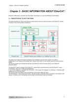
Xtrapuls – EtherCAT Fieldbus Interface Chapter 2 - BASIC INFORMATION ABOUT EtherCAT EtherCAT (“Ethernet for Controller and Automation Technology”) is a real-time Ethernet-based fieldbus. 2.1 - MAIN ETHERCAT SLAVE FUNCTIONS The following EtherCAT slave node reference model makes it easy to locate the impact of the EtherCAT specific functions on the communication architecture. CANopen Profile Object Dictionary Application Layer Data Link Layer EtherCAT State Machine Distributed Clock EtherCAT Data Link Layer Physical Layer Ethernet Physical Layer (100Base-TX or 100Base-FX) or LVDS The green box...
Open the catalog to page 5
Xtrapuls - EtherCAT Fieldbus Interface The EtherCAT master controls the following state machine in every slave: Description of the states and the transitions: Description Initial state at the power on. Amplifier configuration is performed. No communication. SM0 and SM1 are active : SDO exchange is possible. SM0, SM1, SM3 are active : SDO and TPDO exchange is possible. DC generates event. SM0, SM1, SM2 and SM3 are active : SDO, TPDO and RPDO exchange is possible. DC generates event. Chapter 2 - Basic information about EtherCAT®
Open the catalog to page 6
Xtrapuls - EtherCATFieldbus Interface In motion control applications, EtherCAT slaves are connected together in one line. The physical layer technology employed by the EtherCAT fieldbus is the 100BASE-TX. The EtherCAT master is connected at one end of the line. Sockets on EtherCAT slaves are labelled “IN” and “OUT”. The EtherCAT Master should be connected to the first EtherCAT Slave using the “IN” socket of the EtherCAT slave. Each drive have his specifics vendor ID and product codes. Chapter 3 - Electrical installation
Open the catalog to page 7
Xtrapuls - EtherCAT Fieldbus Interface 3.1.1 - XtrapulsGem, XtrapulsPac, and Xtrapuls PacHP connectors and cables On the XtrapulsGem EtherCAT extension board, the EtherCAT fieldbus connectors E3 and E4 are located on the front panel. On the XtrapulsPac drive, the EtherCAT fieldbus connectors X6 and X7 are located on the top of the drive. On the XtrapulsPacHP drive, the EtherCAT fieldbus connectors X6 and X7 are located on the front panel. The cables used for the EtherCAT network must fulfil the following requirements: - Allowed cable conception: o F/UTP: general Foil + Unshielded Twisted Pair...
Open the catalog to page 8
Xtrapuls - EtherCATFieldbus Interface 3.1.2 - XtrapulsIRD connectors and cables The cables used for the EtherCAT network must fulfil the following requirements: - Allowed cable conception : S/FTP: general Shield (with shield pin recovery) + Foiled Twisted Pair ; - Maximum cable length: 30m from EtherCAT master to the last slave. 3.1.1.3 Exemple of XtrapulsIRD daisy chaining For the daisy chaining of the XtrapulsIRD both straight or crossed connection between the RX and TX can be made. 3.2 - INDICATORS Four LEDs are available for quick diagnosis purposes on the XtrapulsPac, XtrapulsPacHP and XtrapulsGem...
Open the catalog to page 9
Xtrapuls – EtherCAT Fieldbus Interface Link/Activity indicators Run/Error indicators On the XtrapulsIRD, only Run/Error indicators are presents. Chapter 3 – Electrical installatio
Open the catalog to page 10
Xtrapuls - EtherCATFieldbus Interface 3.2.1 - Link/Activity Indicators (XtrapulsGem, XtrapulsPac, and Xtrapuls PacHP only) These two LEDs are integrated in RJ-45 sockets The green led “run” highlights the status of the EtherCAT state machine. Blinking Single Flash On The red led “ERR” highlights the error of the EtherCAT state machine. No error Booting error Invalid Configuration Unsollicited state change Application watchdog timeout Flickering Blinking Single Flash Double Flash 3.3 SLAVE ADDRESSING MODES The EtherCAT master has the possibility to use 3 addressing modes: Logical addressing: this...
Open the catalog to page 11
Xtrapuls - EtherCAT Fieldbus Interface All four Sync Manager channels need to be setup by the EtherCAT master during the communication initialisation phases according to the device description file “Infranor_Xtrapuls_Vx_x.xml”. All of the Xtrapuls parameters can be accessed through the SDO communication channel which is carried in the EtherCAT telegrams. Please see “Xtrapuls User Guide” for more details about the available objects. SDO services encapsulated into the EtherCAT telegrams are only 8 byte long. Specific objects OF the EtherCAT Chapter 4 - Specifications of the SDOs and PD0s for the...
Open the catalog to page 12
Xtrapuls - EtherCATFieldbus Interface 4.1.2 - Sync manager channel 0 PDO assignment Value description Chapter 4 - Specifications of the SDOs and PD0s for the EtherCAT
Open the catalog to page 13
Xtrapuls - EtherCAT Fieldbus Interface 4.1.4 - Sync manager channel 2 PDO assignment Chapter 4 - Specifications of the SDOs and PD0s for the EtherCAT
Open the catalog to page 14
Xtrapuls - EtherCATFieldbus Interface 4.1.6 - Synchronisation clock object ESC register read sequence has to be performed as follows: 1- write into the object (index 0x2320 sub-index 0) the address of the ESC register to be read 2- read from the object the data stored at the previously written address Chapter 4 - Specifications of the SDOs and PD0s for the EtherCAT
Open the catalog to page 15All Infranor Group catalogs and technical brochures
 XtrapulsPac_EN
4 Pages
 SMTBSi-2Tz_en_2.1
43 Pages
 PacSimBox_d_1
1 Page
 Pac-SF01_flyer_en_18.02
4 Pages
 Pac_User_1.2.1.218
253 Pages
 Pac_Templates_en_1.9
27 Pages
 Pac_STO_Installation_en_2.2
13 Pages
 Pac_SF01_operating_en_1.6
63 Pages
 Pac_SF01_EN
4 Pages
 Pac_Installation_en_2.23
82 Pages
 Pac_flyer_en_17.12
4 Pages
 Option_CT_EMF
6 Pages
 MOVINOR_LH055_LH086_LH097_LH142
23 Pages
 ma_series
6 Pages
 GemSafeTorqueOff_en_1.1
12 Pages
 CD1pm_e_1.2(old)
18 Pages
 CD1pInst_e_7.2(old)
35 Pages
 CD1kInst_e_4.1(old)
40 Pages
 CD1k_CANopenProtocol_e_1.3(old)
86 Pages
 CD1a_e_7.1(old)
45 Pages
 Catalogue gamme SMT-BD1
11 Pages
 BM20A(F)v3_0
20 Pages
 BM20A(D)v3_0
20 Pages
 BF400(GB)v2_2
21 Pages
 BF400(D)v2_2
21 Pages
 BF230(GB)v2_0
23 Pages
 BF230(F)v2_0
23 Pages
 BD2m_e_2.2
69 Pages
 BD2m(GB)2.0
70 Pages
 BD2_e_3.2
53 Pages
 BD2(GB)3.1
53 Pages
 BD2(D)3.1
54 Pages
 Movinor_LH_e
4 Pages
 ma_series
6 Pages
 BD1t(GB)3.1
81 Pages
 BD1t(F)3.0
85 Pages
 BD1pInst(GB)3.0
25 Pages
 BD1pInst(F)3.0
23 Pages
 BD1pInst(D)3.0
24 Pages
 BD1pCD1pUse_e_2.4
57 Pages
 BD1m(GB)5.0
58 Pages
 BD1m(F)5.0
57 Pages
 BD1m(D)v3_3
64 Pages
 BD1k(GB)2.1
35 Pages
 BD1k(F)2.1
36 Pages
 BD1j(GB)v2_41
19 Pages
 BD1j(F)v2_4
21 Pages
 BD1i(GB)v2_21
23 Pages
 BD1i(F)v2_2
27 Pages
 BD1h(F)3.0
65 Pages
 BD1h(D)3.0
59 Pages
 BD1g(GB)v3_0
28 Pages
 BD1g(F)v3_0
28 Pages
 BD1a400(GB)v2_3
43 Pages
 BD1a400(F)v2_3
44 Pages
 BD1a400(D)v2_3
45 Pages
 BD1(GB)7.1_noPW
45 Pages
 BD1(GB)7.1
45 Pages
 BD1(F)7.1_noPW
47 Pages
 BD1(F)7.1
47 Pages
 BD1(D)7.1
45 Pages
 BD1 Katalog
11 Pages
 Easy_User_5.0.1.60.2
190 Pages
 01ma_smv_e_01953
40 Pages
 PacHP-SF_Flyer_en_23.06
4 Pages
 IRD_User_Manual_en_1.2.XX.54.rev_b
216 Pages
 PacHP_User_en_1.2.8.100.b
280 Pages
 PacHP_SF02_operating_en_1.6
103 Pages
 PacHP_SF01_operating_en_2.0
63 Pages
 PacHP_Installation_en_2.9
91 Pages
 PacHP_Series_Brochure
8 Pages
 PacHP_Flyer_us_20.10
4 Pages
 IRD_Installation_en_1.5
42 Pages
 Easy_STO_en_1.4
14 Pages
 Easy_DB_STO_en_1.2
14 Pages
 Easy_DB_Installation_en_1.4
36 Pages
 CD1pmUser_en_4.2
55 Pages
 CD1pmInst_en_8.15
40 Pages
 CD1k_CANopenProtocol_en_2.10.1.1
108 Pages
 CD1pm_ProfibusProtocol_en_1.5
50 Pages
 CD1kUser_en_2.3
26 Pages
 CD1a_en_8.17
62 Pages
 CD1kInst_en_5.16
46 Pages
 CD1_STO_en_1.8
16 Pages
 CD1_flyer_en_14.09
4 Pages
 Braking_Resistors_en_1.5
10 Pages
 XtracontrolDC2_EN
4 Pages
 Flyer_VisiTouchCNC_EN_V1.1-1
2 Pages
 XtraforsWashdown_EN-2024
2 Pages
 DataSheet_CybIO_CNC_V1.0
6 Pages
 XtraforsPrime_EN-2024
2 Pages
 XtraforsMSS_EN
4 Pages
 XtraforsMSA_EN_2024
2 Pages
 XtraforsEx_EN-2024
2 Pages
 XtraforsBR_EN-2024
2 Pages
 XtraforsBL_EN-2024
2 Pages
 XtraforsBC-ed01-vs3
4 Pages
 Manual_XtraforsPrime
46 Pages
 Drawing_1
1 Page
 Datasheet_MSS
5 Pages
 Datasheet_2
2 Pages
 Datasheet_1
4 Pages
 BLSBLT_series
2 Pages
 BL220221
2 Pages
 BL270
BL2702 Pages
 BL190
BL1902 Pages
 bl100_series
6 Pages
 bl40_series
6 Pages
 BL30
BL302 Pages
 2019-01_XtraforsFP-DSL_FR
4 Pages
 Movinor_T_EN
4 Pages
 Movinor_N_EN
4 Pages
 Movinor_Low_Voltage_EN
4 Pages
 Manual Movinor T 03-2026
46 Pages
 Manual Movinor N 03-2026
63 Pages
 XtrapulsEasy™ AC servo-drive
4 Pages
 XtrapulsCD1 AC servo-drives
4 Pages
 CybIO
CybIO6 Pages
 AC SERVOMOTORS
2 Pages
 Movinor® N AC Servomotors
4 Pages






Archived catalogs
 AN_CD1ak_AbsoluteEncoder_en_2.0
10 Pages
 AN_CD1ak_SinCosTracks_e_1.0
7 Pages
 AN_CD1pm_AbsoluteEncoder_en_2.0
10 Pages
 AN_CD1pm_SinCosTracks_e_1.0
7 Pages
 AN_DC_bus_interfacing_en_1.3
5 Pages
 CD1_EC_conformity_24.05
1 Page
 CD1_STO_conformity_19.02
2 Pages
 Easy_EC_Conformity_24_10
1 Page
 GDPS_EC_conformity_24.07
1 Page
 IRD_EC_Conformity_25.03
1 Page
 PacHP_TÜV_certificate_25.07
2 Pages
 BD1c(F)v2_01
19 Pages
 BD1c(GB)v2_01
19 Pages
 BD1d(F)v2_01
25 Pages
 BD1d(GB)v2_01
25 Pages
 BD1e(F)v2_01
22 Pages
 BD1f(F)v2_01
17 Pages
 BD1f(GB)v2_01
18 Pages
 Pac_EC_conformity_25.04
1 Page




















