
- Catalogs
- Infranor Group
- Easy_User_5.0.1.60.2


Easy_User_5.0.1.60.2

Easy_User_5.0.1.60.2
XtrapulsEasy™ is a series of digital servo drives for controlling brushless AC motors using sinusoidal PWM control. They are cost-effective and support interfaces like CANopen and analog, with integrated Safe Torque Off (STO) protection.
The drive is configurable with parameters for servo-loop, motor, sensor, communication, and I/O, stored in non-volatile memory. Control is via CANopen, analog input, or digital I/Os.
Commissioning uses "Gem Drive Studio" software, compatible with Windows®. It requires a Pentium III processor, 512 MB RAM, and Windows XP SP2. Installation involves unzipping and following setup instructions.
- Uninstall previous Gem Drive Studio versions before new installations.
- Use "." as a decimal separator.
- Installation requires an Administrator session.
Devices are WEEE classified and should be disposed of per regulations. Safety includes waiting 10 minutes post-power down to avoid voltage risks.
Drives are ESD protected but should be stored in original packaging and handled with ESD protection equipment.
Software consists of modules communicating via a server, which starts/stops with client connections. Data format is consistent across communication types.
Different user levels exist, with the administrator having full access. Passwords can be changed by the administrator.
Gem Drive Studio allows drive parameterization within a project, with unique node IDs for each drive.
Refer to the "Installation Guide" before powering drives. Communication is via RS232 or CANopen, with adjustable CAN bus baudrate.
Configuration involves enabling the drive, selecting control methods, and setting motor operation parameters.
Motors can be selected from a catalog or configured manually with parameters like current limits and speed limits.
Sensors are configured based on application needs, with settings for resolution and direction reversal.
Includes low speed threshold, reverse direction, current limit adjustment, and current loop adjustment.
Includes controller type selection, position loop requirements, speed measurement filter, and servo loop filter type.
Includes cut-off frequencies, profile velocity and position modes, and logic inputs and outputs.
Defines the communication cycle period for synchronization in interpolated position mode.
Each drive must have a unique Node ID. SDO messages facilitate communication between drives.
EMCY message behavior is defined by object 0x205F, with options for message sending upon errors.
Object 0x205E defines the drive's response to Node guarding errors.
Manages communication status, transitioning through states like Initialization and Operational.
Signals when a NMT slave enters the PRE-OPERATIONAL state.
Outlines possible states and transitions affecting drive status and functionality.
Manage and indicate drive status with specific bit patterns for control commands.
Object 0x3440 allows activation of drive-specific functions.
Indicated by object at Index 0x3441, showing current status of drive-specific functions.
Errors are displayed in objects 0x3022,1 and 0x3022,2, with emergency messages sent with the last error code.
Each error has a specific bit value and error code, with troubleshooting steps provided.
Includes actual position, following error window, and position deadband window.
Allows selection between internal and external feedforward speed and acceleration.
Includes auto-tuning parameters and gains calculation procedure.
Store and restore drive parameters to/from internal flash memory.
Lists various operational modes supported by the drive.
Involves a trapezoidal trajectory generator for positioning.
Describes linear, PV, and P3 interpolation modes.
Allows operation with a velocity reference, closing only speed and current loops.
Operates with current loops without speed or position control.
Allows for basic moves with sequences like positioning and homing.
Outlines parameters for searching the homing position of a motor.
Allows the axis to move with a profile speed.
Involves moving the axis with a profile speed and a current limit.
Controlled by parameters like SeqCount and SeqNext.
Defines sequence type, execution order, and conditions for starting and stopping sequences.
Defined by indices 0x3601 and 0x3602.
Includes positioning, homing, velocity, torque, gearbox, and cam sequences.
Provides detailed specifications, procedures, norms, recommendations, and key data from tables and diagrams.
Configuration of digital inputs and outputs, including analog input and capture function.
Describes the initialization process for updating the system.
Details the programming sequence, including initialization, erasing, and programming steps.
Provides a comprehensive list of parameters and their descriptions.
Configuration of digital inputs and outputs, specifically mentioning 16-bit digital user inputs/outputs.
Details for analog input configuration, including parameters like input gain and offset.
Describes the oscilloscope function support and configuration.
Instructions for updating firmware.
Infranor Group is highlighted as a provider of motion solutions.
Catalog excerpts
DIGITAL SERVO DRIVES FOR BRUSHLESS AC MOTORS XtrapulsEasy™ - User Guide XtrapulsEasy™ User Guid
Open the catalog to page 1
XtrapulsEasy™ - User Guide ! This is a general manual describing a series of servo drives having output capability suitable for driving AC brushless sinusoidal servo motors. Please see also: o XtrapulsEasy™ User Guide for the operation of the drive (commissioning, configuration, ...) o XtrapulsEasy™ STO for the Safe Torque Off function o Gem Drive Studio software Quick Start manual for the drive parameterization. Instructions for storage, use after storage, commissioning as well as all technical details require the MANDATORY reading of the manual before getting the drives operational. Maintenance...
Open the catalog to page 2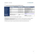
XtrapulsEasy™ - User Guide Information and sorting instructions regarding INFRANOR® products instructions may vary according to regions / countries. INFRANOR does not assume any responsibility for any physical or material damage due to improper handling or wrong descriptions of the ordered items. Any intervention on the items, which is not specified in the manual, will immediately cancel the warranty. INFRANOR reserves the right to change any information contained in this manual without notice.
Open the catalog to page 3
XtrapulsEasy™ - User Guide
Open the catalog to page 4
XtrapulsEasy™ - User Guide Chapter 1 - General Description 1.1 - INTRODUCTION XtrapulsEasy all-digital drives with sinusoidal PWM control are servo drives that provide the control of brushless AC motors. The standard control interface can be: - CANopen, Analog. Series XtrapulsEasy drives are dedicated to basic applications that do not have a high level of requirements in terms of functionalities and where cost effectiveness is very important. XtrapulsEasy drives are delivered as standard with the integrated protection Safe Torque Off : STO SIL 1. The XtrapulsEasy can be used in following typical...
Open the catalog to page 5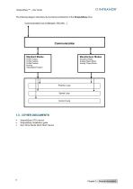
XtrapulsEasy™ - User Guide The following diagram describes the functional architecture of the XtrapulsEasy drive: Standard Modes Manufacturer Modes Profile Torque Profile Velocity Profile Position Homing Interpolated Position Sequence Mode Analog Speed Mode Analog Torque Mode Position Loop Speed Loop Current Loop XtrapulsEasy STO manual XtrapulsEasy Installation guide Gem Drive Studio Quick Start manual
Open the catalog to page 6
XtrapulsEasy™ - User Guide This chapter describes the commissioning procedure of the drive by means of the "Gem Drive Studio" software. Do not perform the drive parameterization by means of both "Gem Drive Studio" software tool and CANopen bus at the same time. The Gem Drive Studio software is PC compliant under Windows® and allows an easy parameterization of the Xtrapuls drive. Please see our website www.infranor.com for downloading the “Gem Drive Studio” software. Minimum Configuration The use of the Gem Drive Studio software requires the minimum PC configuration described below: • 15" screen,...
Open the catalog to page 7
XtrapulsEasy ™ - User Guide Former versions can also be uninstalled from the menu "Start/Gem Drive Studio/Uninstall Gem Drive Studio". B. If the installation program is detecting that files already installed on the hard disk are more recent than those of the installation, we advise to keep these hard disk files. C. For a correct operation of the software tool, use ONLY the dot "." as decimal separator when entering digital values. Do not use any thousands separator. D. The installation of Gem Drive Studio under Windows XP, Vista or Seven requires the opening of an Administrator session. The software...
Open the catalog to page 8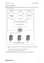
XtrapulsEasy™ - User Guide Architecture of the software The software is made of several independent software modules. Each of them can communicate with the drive(s) via a communication server. Client module Client module Client module Communication server Serial port or CAN port The server is automatically started when a client module is trying to establish a communication with a drive. The server is commissioning the drivers of the hardware peripherals. The server stops when the last connected client is stopped. The format of the exchanged data is the same whichever the communication type (RS232,...
Open the catalog to page 9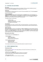
XtrapulsEasy ™ - User Guide When starting the software, various user levels can be selected. The drive parameter modification levels are protected by passwords. Administrator is the highest level with full access. The Administrator can change all passwords by using the Tools/User identification menu. The default password for the administrator level is "admin". The Gem Drive Studio software allows the parameterization of all Xtrapuls drives for a given application. All Xtrapuls drives of a given application, connected together via CANopen, are included in the same project. Each Xtrapuls drive...
Open the catalog to page 10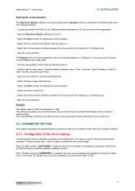
XtrapulsEasy™ - User Guide The Gem Drive Studio software can communicate with an Xtrapuls drive by using either the RS232 serial link or the CANopen fieldbus. - Connect the serial link RS232 or the CANopen fieldbus between the PC and one drive of the application, - Start the Gem Drive Studio software on the PC, - Select the Scan function for starting the communication, - Select the drive node ID (the default node ID value is 1), - Select the communication interface between the drives and the PC (Serial link or CANopen bus), All Xtrapuls drives of a given application can be connected together...
Open the catalog to page 11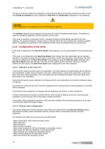
XtrapulsEasy™ - User Guide The drive can also be enabled and disabled by using directly the IN4 input internally connected to Inhibit. In this case Enable by hardware must be configured on High level (the Rising edge configuration is not operating). CAUTION ! This configuration is not suitable for the drive STO function operation. The AutoStart selection allows setting the control word bit 4 with the hardware enable signal. This selection is useful for standalone application with the sequence control mode. If the motor is operating in sensorless control, a phasing procedure is automatically executed...
Open the catalog to page 12All Infranor Group catalogs and technical brochures
 XtrapulsPac_EN
4 Pages
 SMTBSi-2Tz_en_2.1
43 Pages
 PacSimBox_d_1
1 Page
 Pac-SF01_flyer_en_18.02
4 Pages
 Pac_User_1.2.1.218
253 Pages
 Pac_Templates_en_1.9
27 Pages
 Pac_STO_Installation_en_2.2
13 Pages
 Pac_SF01_operating_en_1.6
63 Pages
 Pac_SF01_EN
4 Pages
 Pac_Installation_en_2.23
82 Pages
 Pac_flyer_en_17.12
4 Pages
 Option_CT_EMF
6 Pages
 MOVINOR_LH055_LH086_LH097_LH142
23 Pages
 ma_series
6 Pages
 GemSafeTorqueOff_en_1.1
12 Pages
 CD1pm_e_1.2(old)
18 Pages
 CD1pInst_e_7.2(old)
35 Pages
 CD1kInst_e_4.1(old)
40 Pages
 CD1k_CANopenProtocol_e_1.3(old)
86 Pages
 CD1a_e_7.1(old)
45 Pages
 Catalogue gamme SMT-BD1
11 Pages
 BM20A(F)v3_0
20 Pages
 BM20A(D)v3_0
20 Pages
 BF400(GB)v2_2
21 Pages
 BF400(D)v2_2
21 Pages
 BF230(GB)v2_0
23 Pages
 BF230(F)v2_0
23 Pages
 BD2m_e_2.2
69 Pages
 BD2m(GB)2.0
70 Pages
 BD2_e_3.2
53 Pages
 BD2(GB)3.1
53 Pages
 BD2(D)3.1
54 Pages
 Movinor_LH_e
4 Pages
 ma_series
6 Pages
 BD1t(GB)3.1
81 Pages
 BD1t(F)3.0
85 Pages
 BD1pInst(GB)3.0
25 Pages
 BD1pInst(F)3.0
23 Pages
 BD1pInst(D)3.0
24 Pages
 BD1pCD1pUse_e_2.4
57 Pages
 BD1m(GB)5.0
58 Pages
 BD1m(F)5.0
57 Pages
 BD1m(D)v3_3
64 Pages
 BD1k(GB)2.1
35 Pages
 BD1k(F)2.1
36 Pages
 BD1j(GB)v2_41
19 Pages
 BD1j(F)v2_4
21 Pages
 BD1i(GB)v2_21
23 Pages
 BD1i(F)v2_2
27 Pages
 BD1h(F)3.0
65 Pages
 BD1h(D)3.0
59 Pages
 BD1g(GB)v3_0
28 Pages
 BD1g(F)v3_0
28 Pages
 BD1a400(GB)v2_3
43 Pages
 BD1a400(F)v2_3
44 Pages
 BD1a400(D)v2_3
45 Pages
 BD1(GB)7.1_noPW
45 Pages
 BD1(GB)7.1
45 Pages
 BD1(F)7.1_noPW
47 Pages
 BD1(F)7.1
47 Pages
 BD1(D)7.1
45 Pages
 BD1 Katalog
11 Pages
 01ma_smv_e_01953
40 Pages
 PacHP-SF_Flyer_en_23.06
4 Pages
 IRD_User_Manual_en_1.2.XX.54.rev_b
216 Pages
 PacHP_User_en_1.2.8.100.b
280 Pages
 PacHP_SF02_operating_en_1.6
103 Pages
 PacHP_SF01_operating_en_2.0
63 Pages
 PacHP_Installation_en_2.9
91 Pages
 PacHP_Series_Brochure
8 Pages
 PacHP_Flyer_us_20.10
4 Pages
 IRD_Installation_en_1.5
42 Pages
 Easy_STO_en_1.4
14 Pages
 Easy_DB_STO_en_1.2
14 Pages
 Easy_DB_Installation_en_1.4
36 Pages
 CD1pmUser_en_4.2
55 Pages
 CD1pmInst_en_8.15
40 Pages
 CD1k_CANopenProtocol_en_2.10.1.1
108 Pages
 CD1pm_ProfibusProtocol_en_1.5
50 Pages
 CD1kUser_en_2.3
26 Pages
 CD1a_en_8.17
62 Pages
 CD1kInst_en_5.16
46 Pages
 CD1_STO_en_1.8
16 Pages
 CD1_flyer_en_14.09
4 Pages
 Braking_Resistors_en_1.5
10 Pages
 XtracontrolDC2_EN
4 Pages
 Flyer_VisiTouchCNC_EN_V1.1-1
2 Pages
 XtraforsWashdown_EN-2024
2 Pages
 DataSheet_CybIO_CNC_V1.0
6 Pages
 XtraforsPrime_EN-2024
2 Pages
 XtraforsMSS_EN
4 Pages
 XtraforsMSA_EN_2024
2 Pages
 XtraforsEx_EN-2024
2 Pages
 XtraforsBR_EN-2024
2 Pages
 XtraforsBL_EN-2024
2 Pages
 XtraforsBC-ed01-vs3
4 Pages
 Manual_XtraforsPrime
46 Pages
 Drawing_1
1 Page
 Datasheet_MSS
5 Pages
 Datasheet_2
2 Pages
 Datasheet_1
4 Pages
 BLSBLT_series
2 Pages
 BL220221
2 Pages
 BL270
BL2702 Pages
 BL190
BL1902 Pages
 bl100_series
6 Pages
 bl40_series
6 Pages
 BL30
BL302 Pages
 2019-01_XtraforsFP-DSL_FR
4 Pages
 Movinor_T_EN
4 Pages
 Movinor_N_EN
4 Pages
 Movinor_Low_Voltage_EN
4 Pages
 Manual Movinor T 03-2026
46 Pages
 Manual Movinor N 03-2026
63 Pages
 XtrapulsEasy™ AC servo-drive
4 Pages
 XtrapulsCD1 AC servo-drives
4 Pages
 CybIO
CybIO6 Pages
 AC SERVOMOTORS
2 Pages
 Movinor® N AC Servomotors
4 Pages






Archived catalogs
 AN_CD1ak_AbsoluteEncoder_en_2.0
10 Pages
 AN_CD1ak_SinCosTracks_e_1.0
7 Pages
 AN_CD1pm_AbsoluteEncoder_en_2.0
10 Pages
 AN_CD1pm_SinCosTracks_e_1.0
7 Pages
 AN_DC_bus_interfacing_en_1.3
5 Pages
 CD1_EC_conformity_24.05
1 Page
 CD1_STO_conformity_19.02
2 Pages
 EtherCAT Interface_en_1.3
20 Pages
 Easy_EC_Conformity_24_10
1 Page
 GDPS_EC_conformity_24.07
1 Page
 IRD_EC_Conformity_25.03
1 Page
 PacHP_TÜV_certificate_25.07
2 Pages
 BD1c(F)v2_01
19 Pages
 BD1c(GB)v2_01
19 Pages
 BD1d(F)v2_01
25 Pages
 BD1d(GB)v2_01
25 Pages
 BD1e(F)v2_01
22 Pages
 BD1f(F)v2_01
17 Pages
 BD1f(GB)v2_01
18 Pages
 Pac_EC_conformity_25.04
1 Page




















