
- Catalogs
- Infranor Group
- Easy_STO_en_1.4


Easy_STO_en_1.4

Easy_STO_en_1.4
The document is a manual for the "Safe Torque Off" (STO) function in XtrapulsEasy 60VDC digital servo drives, designed for brushless AC motors. It provides safety and operational guidelines, emphasizing the importance of reading the manual before use.
The STO function is defined by the EN 61800-5-2 standard to prevent motor rotation by cutting power. It is suitable for uncontrolled stopping (Stop Category 0) and may require additional measures like mechanical brakes. It meets EN ISO 13849-1:2017 category 1 PLc requirements, equivalent to SIL1.
The STO function operates by removing IGBT command supply and PWM signals, ensuring the motor shaft remains free. Safety function channels are highlighted in green, while non-safety components are in black.
Integrating the STO function requires a comprehensive risk analysis. Safety instructions include installing the drive in a control cabinet with IP54 protection and ensuring short-circuit detection. The STO function does not shut down the power supply, so electrical risks remain.
The STO connection uses a SUB D 15 PIN MALE HD CONNECTOR, with specific input voltage and impedance requirements. The activation/release response time is a maximum of 50 ms, with additional initialization delays.
The STO function fulfills category 1/PLc requirements, with an MTTFd of 628 years and no average diagnostic coverage. A table is provided for combining safety-related parts to achieve overall PL.
The STO function should be checked annually and during machine safety validation. The procedure involves verifying the motor's torque provision at different input states.
There is a residual risk of motor shaft rotation in case of a short-circuit between power transistors. Electrical risks persist as the STO function does not provide galvanic insulation.
The manual includes configuration examples for integrating the STO function, emphasizing the need for a risk analysis.
Hardware Configuration: Discusses a low inertia axis application with high resistive torque. It is crucial to disable motor control before activating the STO function. The 'Enable' function is assigned to digital input IN1 to disable PWM control.
Gem Drive Studio Configuration: Requires selecting the rising edge in the 'Enable' configuration and linking IN1 to the ENABLE function. IN4 is not configurable, and the rising edge must be selected when IN4 is used as an STO channel. Stop category 0 is executed when IN4 STO\ is low.
Hardware Configuration: Covers a high inertia axis application with low resistive torque. A safe Stop 1 is performed with a delay between the deceleration ramp and STO activation. The deceleration ramp is not safe according to EN13849-1 as it uses a common drive function. The PILZ safety relay orders the drive to decelerate via the QUICK STOP signal assigned to digital input IN3, followed by a 0.5-second safety delay before activating the STO function.
Gem Drive Studio Configuration: Involves selecting the rising edge in the 'Enable' configuration, linking IN1 to the ENABLE function, and linking IN3 to the QUICK STOP function with reversed polarity (STOP is activated with a logical '0'). Stop category 1 is executed when IN3 Quick STOP is low, according to the Stop Operation parameters.
Catalog excerpts
DIGITAL SERVO DRIVES FOR BRUSHLESS AC MOTORS XtrapulsEasy™ 60VDC STO Safe Torque Off manual
Open the catalog to page 1
XtrapulsEasy "Safe Torque Off" manual ! This manual describes a series of servo drives having output capability suitable for driving AC brushless sinusoidal servo motors. Please see also: o o o XtrapulsEasy Installation Guide for the hardware installation of the drive (mounting, wiring, ...) XtrapulsEasy User Guide for the operation of the drive (commissioning, configuration, ...) Gem Drive Studio software Quick Start manual for the drive parameterization. Instructions for storage, use after storage, commissioning as well as all technical details require the MANDATORY reading of the manual before...
Open the catalog to page 2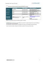
XtrapulsEasy "Safe Torque Off' manual Information and sorting instructions regarding INFRANOR® products Sorting instructions may vary according to regions / countries. INFRANOR does not assume any responsibility for any physical or material damage due to improper handling or wrong descriptions of the ordered items. Any intervention on the items, which is not specified in the manual, will immediately cancel the warranty. Infranor reserves the right to change any information contained in this manual without notice.
Open the catalog to page 3
XtrapulsEasy "Safe Torque Off” manual OINFRANOR
Open the catalog to page 4
XtrapulsEasy "Safe Torque Off" manual Chapter 1 - General description Safe Torque Off (STO) definition according to the EN 61800-5-2 standard: "Power, that can cause the rotation of a motor (or displacement in the case of a linear motor), is not applied to the motor. The drive will not provide energy to the motor which can generate torque (or force in the case of a linear motor)". Used alone, the STO function corresponds to an uncontrolled stopping in accordance with the stop category 0 of the EN 60204-1 standard. The STO function may be used where power removal is required to prevent an unexpected...
Open the catalog to page 5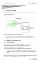
XtrapulsEasy "Safe Torque Off" manual 2.1 - FUNCTIONAL DIAGRAM The "Safe Torque Off" function allows keeping the motor shaft free by avoiding the IGBT module commutation. This is achieved by means of two techniques: - IGBT command supply removal, - PWM removal. XtrapulsEasy drive PWM INTELLIGENT POWER MODULE BUFFER The different parts of the functional diagram are described below: • • The green part is the channel of the safety function. PWM signals are disabled by inhibiting the buffer commutation. The black part is the functional part of the drive which is not used to achieve the safety function....
Open the catalog to page 6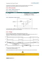
XtrapulsEasy "Safe Torque Off" manual OINFRANOR9 In applications with vertical axes, additional measures (mechanical brake) may be necessary. Please, refer to the EN13849-2 standard for any complementary information. *) From serial number 11420004, the capacitor value is 10 pF for the IN4 input only, in order to support safety relays with test pulse output (for short-circuit detection). The STO function has an activation / release response time of max. 50 ms. However, an additional delay of 6.5 ms is necessary for initialization before PWM becomes active, and 2 s in "Sensorless" or "HES only"...
Open the catalog to page 7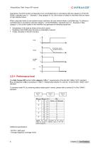
XtrapulsEasy "Safe Torque Off" manual Used alone, the STO function corresponds to an uncontrolled stop in accordance with stop category 0 of the EN 60204-1 standard (see 3.1 - Example 1: Stop category 0). So, this function is suited for machines with low inertia or high resistive torque. When using high inertia or low resistive torque machines, the user should initiate a controlled stop. To achieve a controlled stop in accordance with stop category 1 of the EN 60204-1 standard (see 3.2 - Example 2: Stop category 1), the control system of the machine must generate the following sequences: ■ Deceleration...
Open the catalog to page 8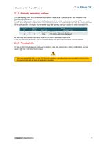
XtrapulsEasy "Safe Torque Off" manual The well-working of the function needs to be checked at least once a year and during the validation of the machine safety functions. The goal of this procedure is to verify that all subsystems of the safety function are operational. The command system must integrate a checking mode reserved to an operator aware of potential risks due to a wrong operation of the safety system. It is highly recommended to get the operator signing a register in order to sensitize him. At each step, the operator must verify whether the motor is providing torque or not. If the...
Open the catalog to page 9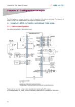
XtrapulsEasy "Safe Torque Off" manual The following diagram examples are given to make the integration of the safety function easier. The integration of the STO function must be the result of a risk analysis of the global machine.3.1 - EXAMPLE 1: STOP CATEGORY 0 ACCORDING TO EN 60204-13.1.1 - Hardware configurationLow inertia axis application / high resistive torque XtrapulsEasy-ak-230/17 Power relay remote control Motor U phase 1 Motor V phase 2 Motor W phase Use only copper conductors for the wiring terminations. The torque values of the wiring terminations must comply with the certified blockterminal....
Open the catalog to page 10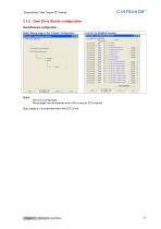
XtrapulsEasy "Safe Torque Off" manual Link IN1 to ENABLE function Basic digital inputs configuration Physical input 17 flN4 3~ r | None 3~ r |None ^— r |None 3 r I None TJ— r | None 3~ r |None ^ r | None jJ— r[None 3— r |None 3 r |None 3 r |None 3— r |None ^ r I None jJ— r | None 3_ r |None ^— r I None jJ— Chapter 3 - Connection examples Reset configuration Reversed polarity Reversed polarity Reversed polarity Reversed polarity Reversed polarity Reversed polarity Reversed polarity Reversed polarity Reversed polarity Reversed polarity Reversed polarity Reversed polarity Reversed polarity Reversed...
Open the catalog to page 11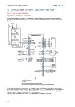
XtrapulsEasy "Safe Torque Off" manual High inertia axis application /low resistive torque In the following example, a safe Stop 1 is performed. The delay between the deceleration ramp and the STO activation is safe. The deceleration ramp is not safe according to EN13849-1 because it uses a common drive function. Use only copper conductors for the wiring terminations. The torque values of the wiring terminations must comply with the certified blockterminal. In the connection diagram example above, the PILZ safety relay orders the drive to decelerate via the QUICK STOP signal (assigned to digital...
Open the catalog to page 12All Infranor Group catalogs and technical brochures
 XtrapulsPac_EN
4 Pages
 SMTBSi-2Tz_en_2.1
43 Pages
 PacSimBox_d_1
1 Page
 Pac-SF01_flyer_en_18.02
4 Pages
 Pac_User_1.2.1.218
253 Pages
 Pac_Templates_en_1.9
27 Pages
 Pac_STO_Installation_en_2.2
13 Pages
 Pac_SF01_operating_en_1.6
63 Pages
 Pac_SF01_EN
4 Pages
 Pac_Installation_en_2.23
82 Pages
 Pac_flyer_en_17.12
4 Pages
 Option_CT_EMF
6 Pages
 MOVINOR_LH055_LH086_LH097_LH142
23 Pages
 ma_series
6 Pages
 GemSafeTorqueOff_en_1.1
12 Pages
 CD1pm_e_1.2(old)
18 Pages
 CD1pInst_e_7.2(old)
35 Pages
 CD1kInst_e_4.1(old)
40 Pages
 CD1k_CANopenProtocol_e_1.3(old)
86 Pages
 CD1a_e_7.1(old)
45 Pages
 Catalogue gamme SMT-BD1
11 Pages
 BM20A(F)v3_0
20 Pages
 BM20A(D)v3_0
20 Pages
 BF400(GB)v2_2
21 Pages
 BF400(D)v2_2
21 Pages
 BF230(GB)v2_0
23 Pages
 BF230(F)v2_0
23 Pages
 BD2m_e_2.2
69 Pages
 BD2m(GB)2.0
70 Pages
 BD2_e_3.2
53 Pages
 BD2(GB)3.1
53 Pages
 BD2(D)3.1
54 Pages
 Movinor_LH_e
4 Pages
 ma_series
6 Pages
 BD1t(GB)3.1
81 Pages
 BD1t(F)3.0
85 Pages
 BD1pInst(GB)3.0
25 Pages
 BD1pInst(F)3.0
23 Pages
 BD1pInst(D)3.0
24 Pages
 BD1pCD1pUse_e_2.4
57 Pages
 BD1m(GB)5.0
58 Pages
 BD1m(F)5.0
57 Pages
 BD1m(D)v3_3
64 Pages
 BD1k(GB)2.1
35 Pages
 BD1k(F)2.1
36 Pages
 BD1j(GB)v2_41
19 Pages
 BD1j(F)v2_4
21 Pages
 BD1i(GB)v2_21
23 Pages
 BD1i(F)v2_2
27 Pages
 BD1h(F)3.0
65 Pages
 BD1h(D)3.0
59 Pages
 BD1g(GB)v3_0
28 Pages
 BD1g(F)v3_0
28 Pages
 BD1a400(GB)v2_3
43 Pages
 BD1a400(F)v2_3
44 Pages
 BD1a400(D)v2_3
45 Pages
 BD1(GB)7.1_noPW
45 Pages
 BD1(GB)7.1
45 Pages
 BD1(F)7.1_noPW
47 Pages
 BD1(F)7.1
47 Pages
 BD1(D)7.1
45 Pages
 BD1 Katalog
11 Pages
 Easy_User_5.0.1.60.2
190 Pages
 01ma_smv_e_01953
40 Pages
 PacHP-SF_Flyer_en_23.06
4 Pages
 IRD_User_Manual_en_1.2.XX.54.rev_b
216 Pages
 PacHP_User_en_1.2.8.100.b
280 Pages
 PacHP_SF02_operating_en_1.6
103 Pages
 PacHP_SF01_operating_en_2.0
63 Pages
 PacHP_Installation_en_2.9
91 Pages
 PacHP_Series_Brochure
8 Pages
 PacHP_Flyer_us_20.10
4 Pages
 IRD_Installation_en_1.5
42 Pages
 Easy_DB_STO_en_1.2
14 Pages
 Easy_DB_Installation_en_1.4
36 Pages
 CD1pmUser_en_4.2
55 Pages
 CD1pmInst_en_8.15
40 Pages
 CD1k_CANopenProtocol_en_2.10.1.1
108 Pages
 CD1pm_ProfibusProtocol_en_1.5
50 Pages
 CD1kUser_en_2.3
26 Pages
 CD1a_en_8.17
62 Pages
 CD1kInst_en_5.16
46 Pages
 CD1_STO_en_1.8
16 Pages
 CD1_flyer_en_14.09
4 Pages
 Braking_Resistors_en_1.5
10 Pages
 XtracontrolDC2_EN
4 Pages
 Flyer_VisiTouchCNC_EN_V1.1-1
2 Pages
 XtraforsWashdown_EN-2024
2 Pages
 DataSheet_CybIO_CNC_V1.0
6 Pages
 XtraforsPrime_EN-2024
2 Pages
 XtraforsMSS_EN
4 Pages
 XtraforsMSA_EN_2024
2 Pages
 XtraforsEx_EN-2024
2 Pages
 XtraforsBR_EN-2024
2 Pages
 XtraforsBL_EN-2024
2 Pages
 XtraforsBC-ed01-vs3
4 Pages
 Manual_XtraforsPrime
46 Pages
 Drawing_1
1 Page
 Datasheet_MSS
5 Pages
 Datasheet_2
2 Pages
 Datasheet_1
4 Pages
 BLSBLT_series
2 Pages
 BL220221
2 Pages
 BL270
BL2702 Pages
 BL190
BL1902 Pages
 bl100_series
6 Pages
 bl40_series
6 Pages
 BL30
BL302 Pages
 2019-01_XtraforsFP-DSL_FR
4 Pages
 Movinor_T_EN
4 Pages
 Movinor_N_EN
4 Pages
 Movinor_Low_Voltage_EN
4 Pages
 Manual Movinor T 03-2026
46 Pages
 Manual Movinor N 03-2026
63 Pages
 XtrapulsEasy™ AC servo-drive
4 Pages
 XtrapulsCD1 AC servo-drives
4 Pages
 CybIO
CybIO6 Pages
 AC SERVOMOTORS
2 Pages
 Movinor® N AC Servomotors
4 Pages






Archived catalogs
 AN_CD1ak_AbsoluteEncoder_en_2.0
10 Pages
 AN_CD1ak_SinCosTracks_e_1.0
7 Pages
 AN_CD1pm_AbsoluteEncoder_en_2.0
10 Pages
 AN_CD1pm_SinCosTracks_e_1.0
7 Pages
 AN_DC_bus_interfacing_en_1.3
5 Pages
 CD1_EC_conformity_24.05
1 Page
 CD1_STO_conformity_19.02
2 Pages
 EtherCAT Interface_en_1.3
20 Pages
 Easy_EC_Conformity_24_10
1 Page
 GDPS_EC_conformity_24.07
1 Page
 IRD_EC_Conformity_25.03
1 Page
 PacHP_TÜV_certificate_25.07
2 Pages
 BD1c(F)v2_01
19 Pages
 BD1c(GB)v2_01
19 Pages
 BD1d(F)v2_01
25 Pages
 BD1d(GB)v2_01
25 Pages
 BD1e(F)v2_01
22 Pages
 BD1f(F)v2_01
17 Pages
 BD1f(GB)v2_01
18 Pages
 Pac_EC_conformity_25.04
1 Page




















