- Catalogs
- Infranor Group
- Easy_DB_Installation_en_1.4


Easy_DB_Installation_en_1.4

Easy_DB_Installation_en_1.4
The XtrapulsEasy™-DB is a digital servo drive designed for controlling brushless AC motors using sinusoidal PWM control. It supports interfaces such as CANopen® and analog, making it suitable for cost-effective applications like CANopen® fieldbus-controlled axes, stand-alone operations, and traditional analog speed drives.
The drive complies with various standards and can be configured in four feedback modes: Resolver or analog Hall, TTL encoder with or without Hall effect sensors, Hall effect sensors only, and Sensorless. Proper installation is necessary for CE approval.
The XtrapulsEasy™-ak-60/45-DB model includes detailed technical specifications, dimensions, and motherboard footprint. It operates with a 24VDC +/- 15% supply, supports various feedback mechanisms, and is programmable via RS-232 and CANopen® interfaces. Key technical data includes a maximum output current of 45Arms, a switching frequency of 8kHz or 16kHz, and a maximum motor speed adjustable from 100 to 25,000 rpm.
The guide details display features, including LEDs and CANopen® communication bus, and describes various connectors for feedback, power, and mechanical mounting.
Recommendations include copper section, power and signal separation, external capacitors, shielding, grounding, and impedance matching. Protections for auxiliary and power supplies are also covered.
Instructions are provided for motor, resolver, encoder cables, serial link, and CAN communication cables. Important notes on the connection of the 24VDC supply and DC Bus are included, along with starting procedures.
The document highlights compliance with the WEEE directive for waste disposal and provides safety warnings regarding electrical parts and ESD precautions.
Includes details on the development kit "DEV01", low operating voltage, maintenance procedures, warranty, and operating environment conditions.
The document provides a detailed installation guide for the XtrapulsEasy™-DB drive, focusing on its specifications, procedures, and standards compliance. It includes information on sensor feedback, power supply requirements, and communication protocols.
The drive complies with Electromagnetic Compatibility standards (EN 61800-3) and safety standards (EN 60204-1, EN 61800-5-2). It is designed for use in industrial environments and meets EC conformity requirements.
The drive features auto-tuning and auto-phasing functions for easy commissioning. The Gem Drive Studio software facilitates parameter configuration and diagnostics, supporting multi-axis setups. Error diagnostics are indicated via LEDs, with specific codes for various faults.
For optimal performance, ensure proper cooling through natural air convection and protect the drive from dust and condensation. The drive should be mounted inside a cabinet meeting pollution degree 2 requirements.
Lists accessories like the Easy-dev01 for external connectors and provides an ordering code breakdown for different drive configurations.
Details pin configurations for CAN communication and RS-232 data transmission. Default CANopen® bus parameters include a transmission speed of 1Mb/s and an address set at 1.
XtrapulsEasy™ drives can operate within a voltage range of 24VDC/17VAC to 60VDC/42VAC. Specifications such as minimum inductance and voltage thresholds vary with operating voltage.
Periodic checks include cooling, dust, corrosion, and mechanical mounting inspections, recommended annually. Any board intervention voids the warranty.
Climatic conditions include air temperature from -40°C to +40°C and relative moisture from 5% to 85% without condensation. Mechanical installation requires mounting on a stiff surface with potential cooling systems.
Abnormal conditions such as exposure to corrosive gases, excessive moisture, or vibrations require special considerations.
Equipment must be stored under conditions specified by IEC standards, avoiding condensation and extreme temperatures. Transport conditions include specific vibration and shock limits.
Infranor provides tailored motion solutions with a global presence in various countries, offering engineering skills and high-quality products.
Catalog excerpts
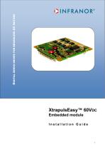
DIGITAL SERVO DRIVES FOR BRUSHLESS AC MOTORS XtrapulsEasy™-DB - Installation Guide XtrapulsEasy™ 60VDC Embedded module Installation Guide
Open the catalog to page 1
XtrapulsEasy™-DB - Installation Guide ! This is a general manual describing a series of servo drives having output capability suitable for driving AC brushless sinusoidal servo motors. Please see also: o XtrapulsEasy™ User Guide for the operation of the drive (commissioning, configuration, ...) o XtrapulsEasy™ DB STO for the Safe Torque Off function o Gem Drive Studio software Quick Start manual for the drive parameterization. Instructions for storage, use after storage, commissioning as well as all technical details require the MANDATORY reading of the manual before getting the drives operational....
Open the catalog to page 2
XtrapulsEasy™-DB - Installation Guide All electrical industrial automatisms which lifetime is coming to its end are Waste Electronic and Electrical Equipment (WEEE) according to article R543-172 of the French Environmental Code. WEEE classification of the INFRANOR® products Categorie 9: Monitoring and control instruments In accordance with the Decree nr. 2012-617 of May 2nd, 2012 which specifies the provisions related to the professional EEE manufacturers' obligations, INFRANOR France is a member of RECYLUM : ecoorganization ecosystem® certified for the collection, treatment and recycling of...
Open the catalog to page 3
XtrapulsEasy™-DB - Installation Guide
Open the catalog to page 4
XtrapulsEasy™-DB - Installation Guide CINFRANOR@
Open the catalog to page 5
XtrapulsEasy™ all-digital drives with sinusoidal PWM control are servo drives that provide the control of brushless AC motors. The standard control interface can be: Series XtrapulsEasy™ drives are dedicated to basic applications that do not have a high level of requirements in terms of functionalities and where cost effectiveness is very important. The XtrapulsEasy™ drive can be used in following typical applications: • Axes controlled by CANopen® fieldbus according to the DS402 protocol, • Stand-alone operation as a sequencer with control by means of logic I/Os, • Traditional analog speed drive...
Open the catalog to page 6
XtrapulsEasy™-DB - Installation Guide Series XtrapulsEasy™ drives have their own DC/DC converter to provide the voltages required for the drive operation with a 24VDC +/- 15 % supply source which is generally available on machines. The auxiliary supply allows keeping the drive logic supplies after the power supply has been switched off. Thus, the position output can be kept without new initializations of the machine. A 24VDC battery supply with specific wiring allows keeping the position even after switching off the auxiliary 24VDC supply. This wiring can be used for getting an "absolute" servo...
Open the catalog to page 7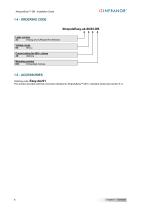
XtrapulsEasy™-DB - Installation Guide 1.4 - ORDERING CODE XtrapulsEasy-ak-60/45-DB Logic version ak: Analog and CANopen® interfaces Voltage range 60: 60VDC Current rating for 60VDC drives 45: 45Arms Mounting version DB: Embedded module 1.5 - ACCESSORIES Ordering code: Easy-dev01 This product provides external connectors identical to XtrapulsEasy™ 60VDC standard series (see section 5.1).
Open the catalog to page 8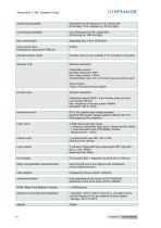
XtrapulsEasy™-DB - Installation Guide OINFRANOFT Speed loop bandwidth
Open the catalog to page 10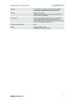
XtrapulsEasy™-DB - Installation Guide O INFRA NOR® Moisture
Open the catalog to page 11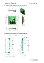
XtrapulsEasy™-DB - Installation Guide The mechanical layout to be implemented on the motherboard is shown below: Top View of the hosting boord
Open the catalog to page 12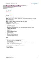
RUN: status of the CANopen® communication bus connection. ERROR: faults grouped on the ‘ERROR’ LED: these errors are coded and can be displayed by means of the parameter setting software. ERROR LED unlit if no fault. ERROR LED flashing: ‘UNDERVOLTAGE’ error: no power supply voltage. ERROR LED continuously lit: fault. The ERROR LED groups the following faults: • Power supply overvoltage. • Motor phase / GND short-circuit. • Motor phase / motor phase short-circuit, power stage overtemperature, defective IGBT module. • Counting error. • Position following error • EEPROM error. • Procedure execution...
Open the catalog to page 13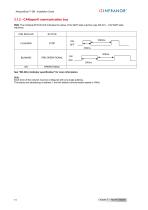
XtrapulsEasy™-DB - Installation Guide 3.1.2 - CANopen® communication bus RUN: The CANopen® RUN LED indicates the status of the NMT state machine (see DS-301 – 9.52 NMT state machine): CAN RUN LED See "DR-303-3 Indicator specification" for more information. Note: Each drive of the network must be configured with one single address. The factory-set addressing is address 1 and the default communication speed is 1Mbit.
Open the catalog to page 14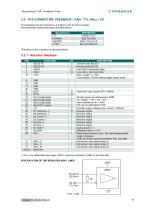
XtrapulsEasy™-DB - Installation Guide The feedback and I/O connector is a 2.54mm pitch 2x15 pins header. Recommended mating references are listed below: (*) For a non differential input signal, ANA1- must be connected to GND on the drive side
Open the catalog to page 15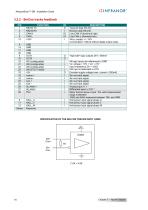
XtrapulsEasy™-DB - Installation Guide SPECIFICATION OF THE SIN COS TRACKS INPUT LINES
Open the catalog to page 16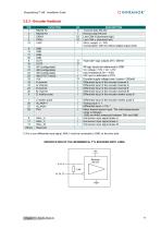
XtrapulsEasy™-DB - Installation Guide (*) For a non differential input signal, ANA1- must be connected to GND on the drive side SPECIFICATION OF THE INCREMENTAL TTL ENCODER INPUT LINES
Open the catalog to page 17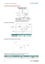
XtrapulsEasy™-DB - Installation Guide SPECIFICATION OF THE HALL SENSOR INPUT LINES
Open the catalog to page 18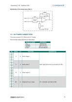
XtrapulsEasy™-DB - Installation Guide OINFRANOR® Specification of the analog inputs ANA1+/- 3.3 - X9: POWER CONNECTORS The power connector is a 2,54mm pitch 2x17 header. Recommended mating references are listed below:
Open the catalog to page 19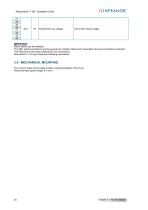
IMPORTANT Motor cable must be shielded. The 360° shield connection must be ensured by metallic collars and connected to the ground reference potential. The GND wire of the motor cable MUST be connected to See section 4.1 for grounding and shielding precautions. 3.4 - MECHANICAL MOUNTING Four 3,2mm holes are provided to allow mechanical fasten of the drive. Recommended spacer length is 12mm.
Open the catalog to page 20
XtrapulsEasy™-DB - Installation Guide Chapter 4 - Design recommendations 4.1 - MOTHERBOARD DESIGN 4.1.1 - Copper section The copper section for motor phases U V W and power source must be at least 0.3mm² on external layers. However, in order to optimize the thermal behaviour (temperature rise less than 10°C), we recommend to maximize the current ability of the design by: Using at least 4-layer PCBs and at least 35µm finished copper thickness, Using maximum trace width according to the connector pitch = 7mm. Note: External layers allow a current 3 times higher than internal layers, thanks to natural...
Open the catalog to page 21All Infranor Group catalogs and technical brochures
 XtrapulsPac_EN
4 Pages
 XtrapulsGemTemplates_e_1.4
21 Pages
 XtrapulsGem_User_Manual_v1.2.0.64
199 Pages
 XtrapulsGem_Inst_e_2.1
42 Pages
 XtrapulsGem_Inst_e_2.0
42 Pages
 SMTBSi-2Tz_en_2.1
43 Pages
 smt-100
32 Pages
 PacSimBox_d_1
1 Page
 Pac-SF01_flyer_en_18.02
4 Pages
 Pac_User_1.2.1.218
253 Pages
 Pac_Templates_en_1.9
27 Pages
 Pac_STO_Installation_en_2.2
13 Pages
 Pac_SF01_operating_en_1.6
63 Pages
 Pac_SF01_EN
4 Pages
 Pac_Installation_en_2.23
82 Pages
 Pac_flyer_en_17.12
4 Pages
 Option_CT_EMF
6 Pages
 MOVINOR_LH055_LH086_LH097_LH142
23 Pages
 ma_series
6 Pages
 GemSafeTorqueOff_en_1.1
12 Pages
 GemProgramming_e_1.1
47 Pages
 GDPS_old_version_1.1_1
11 Pages
 CD1pm_e_1.2(old)
18 Pages
 CD1pInst_e_7.2(old)
35 Pages
 CD1kInst_e_4.1(old)
40 Pages
 CD1k_CANopenProtocol_e_1.3(old)
86 Pages
 CD1a_e_7.1(old)
45 Pages
 Catalogue gamme SMT-BD1
11 Pages
 BM20A(F)v3_0
20 Pages
 BM20A(D)v3_0
20 Pages
 BF400(GB)v2_2
21 Pages
 BF400(D)v2_2
21 Pages
 BF230(GB)v2_0
23 Pages
 BF230(F)v2_0
23 Pages
 BD2m_e_2.2
69 Pages
 BD2m(GB)2.0
70 Pages
 BD2_e_3.2
53 Pages
 BD2(GB)3.1
53 Pages
 BD2(D)3.1
54 Pages
 Movinor_LH_e
4 Pages
 ma_series
6 Pages
 BD1t(GB)3.1
81 Pages
 BD1t(F)3.0
85 Pages
 BD1pInst(GB)3.0
25 Pages
 BD1pInst(F)3.0
23 Pages
 BD1pInst(D)3.0
24 Pages
 BD1pCD1pUse_e_2.4
57 Pages
 BD1m(GB)5.0
58 Pages
 BD1m(F)5.0
57 Pages
 BD1m(D)v3_3
64 Pages
 BD1k(GB)2.1
35 Pages
 BD1k(F)2.1
36 Pages
 BD1j(GB)v2_41
19 Pages
 BD1j(F)v2_4
21 Pages
 BD1i(GB)v2_21
23 Pages
 BD1i(F)v2_2
27 Pages
 BD1h(F)3.0
65 Pages
 BD1h(D)3.0
59 Pages
 BD1g(GB)v3_0
28 Pages
 BD1g(F)v3_0
28 Pages
 BD1a400(GB)v2_3
43 Pages
 BD1a400(F)v2_3
44 Pages
 BD1a400(D)v2_3
45 Pages
 BD1(GB)7.1_noPW
45 Pages
 BD1(GB)7.1
45 Pages
 BD1(F)7.1_noPW
47 Pages
 BD1(F)7.1
47 Pages
 BD1(D)7.1
45 Pages
 BD1 Katalog
11 Pages
 08ma_ms_e_01700
20 Pages
 Easy_User_5.0.1.60.2
190 Pages
 08ma_mrm_em_01575
20 Pages
 01ma_smv_e_01953
40 Pages
 PacHP-SF_Flyer_en_23.06
4 Pages
 IRD_User_Manual_en_1.2.XX.54.rev_b
216 Pages
 PacHP_User_en_1.2.8.100.b
280 Pages
 PacHP_SF02_operating_en_1.6
103 Pages
 PacHP_SF01_operating_en_2.0
63 Pages
 PacHP_Installation_en_2.9
91 Pages
 PacHP_Series_Brochure
8 Pages
 PacHP_Flyer_us_20.10
4 Pages
 IRD_Installation_en_1.5
42 Pages
 GDPS_Installation_en_4.4
18 Pages
 Easy_STO_en_1.4
14 Pages
 Easy_DB_STO_en_1.2
14 Pages
 CD1pmUser_en_4.2
55 Pages
 CD1pmInst_en_8.15
40 Pages
 CD1k_CANopenProtocol_en_2.10.1.1
108 Pages
 CD1pm_ProfibusProtocol_en_1.5
50 Pages
 CD1kUser_en_2.3
26 Pages
 CD1a_en_8.17
62 Pages
 CD1kInst_en_5.16
46 Pages
 CD1_STO_en_1.8
16 Pages
 CD1_flyer_en_14.09
4 Pages
 Braking_Resistors_en_1.5
10 Pages
 XtracontrolDC2_EN
4 Pages
 Flyer_VisiTouchCNC_EN_V1.1-1
2 Pages
 XtraforsWashdown_EN-2024
2 Pages
 DataSheet_CybIO_CNC_V1.0
6 Pages
 XtraforsPrime_EN-2024
2 Pages
 XtraforsMSS_EN
4 Pages
 XtraforsMSA_EN_2024
2 Pages
 XtraforsEx_EN-2024
2 Pages
 XtraforsBR_EN-2024
2 Pages
 XtraforsBL_EN-2024
2 Pages
 XtraforsBC-ed01-vs3
4 Pages
 Manual_XtraforsPrime
46 Pages
 Drawing_1
1 Page
 Datasheet_MSS
5 Pages
 Datasheet_2
2 Pages
 Datasheet_1
4 Pages
 BLSBLT_series
2 Pages
 BL220221
2 Pages
 BL270
BL2702 Pages
 BL190
BL1902 Pages
 bl100_series
6 Pages
 bl40_series
6 Pages
 BL30
BL302 Pages
 2019-01_XtraforsFP-DSL_FR
4 Pages
 Movinor_T_EN
4 Pages
 Movinor_N_EN
4 Pages
 Movinor_Low_Voltage_EN
4 Pages
 Manual Movinor T 03-2026
46 Pages
 Manual Movinor N 03-2026
63 Pages
 XtrapulsEasy™ AC servo-drive
4 Pages
 XtrapulsCD1 AC servo-drives
4 Pages
 CybIO
CybIO6 Pages
 AC SERVOMOTORS
2 Pages
 Movinor® N AC Servomotors
4 Pages






Archived catalogs
 AN_CD1ak_AbsoluteEncoder_en_2.0
10 Pages
 AN_CD1ak_SinCosTracks_e_1.0
7 Pages
 AN_CD1pm_AbsoluteEncoder_en_2.0
10 Pages
 AN_CD1pm_SinCosTracks_e_1.0
7 Pages
 AN_DC_bus_interfacing_en_1.3
5 Pages
 CD1_EC_conformity_24.05
1 Page
 CD1_STO_conformity_19.02
2 Pages
 EtherCAT Interface_en_1.3
20 Pages
 Easy_EC_Conformity_24_10
1 Page
 GDPS_EC_conformity_24.07
1 Page
 IRD_EC_Conformity_25.03
1 Page
 PacHP_TÜV_certificate_25.07
2 Pages
 BD1c(F)v2_01
19 Pages
 BD1c(GB)v2_01
19 Pages
 BD1d(F)v2_01
25 Pages
 BD1d(GB)v2_01
25 Pages
 BD1e(F)v2_01
22 Pages
 BD1f(F)v2_01
17 Pages
 BD1f(GB)v2_01
18 Pages
 CE_conformity_Gem
1 Page
 Pac_EC_conformity_25.04
1 Page
 Pac_GDPS_CEconformity
1 Page
![SMT100D_e_1.01[1]](https://img.directindustry.com/pdf/repository_di/4620720/smt100d-e-101-1-1141223_1mg.jpg) SMT100D_e_1.01[1]
SMT100D_e_1.01[1]40 Pages
 STO_declaration_Gem
2 Pages