
- Catalogs
- Infranor Group
- CD1pmUser_en_4.2


CD1pmUser_en_4.2

CD1pmUser_en_4.2
- Specifications and Safety: The manual outlines mandatory safety precautions, including ESD protection and proper storage to prevent damage. It highlights the importance of waiting five minutes after power down before handling the amplifiers due to residual voltage risks.
- Installation and Commissioning: Detailed instructions are provided for installing PC software, checking hardware configurations, and selecting operation modes. The commissioning process includes motor adjustment, sensor configuration, and servo loop adjustment.
- Functionalities: This section describes the logic I/Os, limit switches, brake control, and PROFIBUS addressing. It provides guidance on configuring the positioner and managing inputs and outputs.
- Programming: The manual covers position scaling, safety limits, manual movements, and positioning profiles. It includes instructions for editing sequences such as homing, positioning, speed, torque, and gearing sequences.
- PROFIBUS Communication: A dedicated section explains the communication protocols and settings required for integrating the amplifiers into a PROFIBUS network.
- Troubleshooting: The manual provides diagnostic procedures, fault finding, and solutions for common operating problems such as motor non-movement, erratic oscillations, and noise issues.
Catalog excerpts
CINFRANOR XtrapulsCD1-pm User manual
Open the catalog to page 1
Windows® is a registered trade-mark of MICROSOFT® CORPORATION. STEP7® is a registered trade-mark of SIEMENS®.
Open the catalog to page 2
! This is a general manual describing a series of servo amplifiers having output capability suitable for driving AC brushless sinusoidal servo motors. Instructions for storage, use after storage, commissioning as well as all technical details require the MANDATORY reading of the manual before getting the amplifiers operational. Please see XtrapulsCD1-pm Installation Guide for the hardware installation of the amplifier (dimensions, wiring, ...). For the PROFIBUS communication, see manual XtrapulsCD1-pm – PROFIBUS Communication Profile. Maintenance procedures should be attempted only by highly...
Open the catalog to page 3
All electrical industrial automatisms which lifetime is coming to its end are Waste Electronic and Electrical Equipment (WEEE) according to article R543-172 of the French Environmental Code. WEEE classification of the INFRANOR products Categorie 9: Monitoring and control instruments In accordance with the Decree nr. 2012-617 of May 2nd, 2012 which specifies the provisions related to the professional EEE manufacturers' obligations, INFRANOR France is a member of RECYLUM : ecoorganization ecosystem certified for the collection, treatment and recycling of WEEE. In France, RECYLUM allows all professionals...
Open the catalog to page 4
Chapter 1 - General description
Open the catalog to page 5
Chapter 1 - General description 1 - INTRODUCTION Series XtrapulsCD1-pm Profibus positioners are PWM servo amplifiers for the control of AC sinusoidal motors (brushless) equipped with a position sensor. The XtrapulsCD1-pm servo drive is available as a stand-alone single-axis block that includes all supplies and mains filter. It is available in both mains operated versions 230 VAC and 400/480 VAC. The XtrapulsCD1-pm positioner generates itself the positioning trajectory and is suited for axis positioning applications. Up to 128 control sequences including axis homing, absolute or relative displacement,...
Open the catalog to page 7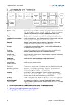
Sequence selection Profibus-DP interface Trajectory generator Position loop Speed loop Current loop Position feedback Speed feedback Current feedback Position sensor Electric motor Electric device that transforms electrical energy into a mechanical movement. This transformation is often made by means of a current commutation. Generally, the movement is a rotation but there are also linear motors. Electric motor which current commutation is made by mechanical brushes. Brushless or synchronous motor Electric brushless motor. The current commutation is electronically made and requires a position...
Open the catalog to page 8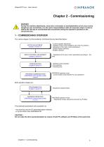
WARNING During the machine adjustments, some drive connection or parameterization errors may involve dangerous axis movements. It is the user's responsibility to take all necessary steps in order to reduce the risk due to uncontrolled axis movements during the operator's presence in the concerned area. 1 – COMMISSIONING OVERVIEW The various stages of a first positioner commissioning are described below: MOTOR ADJUSTMENT (chapter 2 section 7) SERVO CONTROL ADJUSTMENT (chapter 2 section 8) CONFIGURATION (chapter 4 section 2) PROFIBUS COMMUNICATION (PROFIBUS communication profile manual) - Current...
Open the catalog to page 9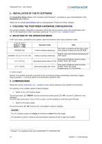
XtrapulsCDI-pm - User manual CINFRANOR2 - INSTALLATION OF THE PC SOFTWARE The Visual Drive Setup software is PC compliant under Windows® 1 and allows an easy parameterization of the XtrapulsCDI-pm amplifiers. Please see our website www.infranor.com for downloading the "Visual Drive Setup" software. The standard amplifier configuration is adjusted to MAVILOR motors (resolver sensor with transformation ratio = 0.5). For the adjustment to other motor types, please see "XtrapulsCD1-pm - Installation Guide". A DIP micro-switch, accessible by the operator, allows the selection of the various operation...
Open the catalog to page 10
6 - STARTING THE "VDSETUP" SOFTWARE • • Connect the serial link RS232 between PC and amplifier. Switch on the amplifier and start the Visual Drive Setup software on the PC, under WINDOWS®. If the message No serial communication found is displayed on the screen, click on OK and check the following points: o o o The amplifier must be on, The correct RS232 connection between amplifier and PC, The correct software configuration (Com.port, ...). For the parameterization of the amplifier via the Visual Drive Setup software, set all DIP micro-switches at position OFF (address 00). 7 - MOTOR ADJUSTMENT...
Open the catalog to page 11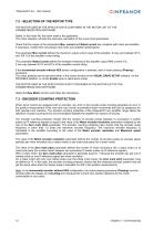
7.2 - SELECTION OF THE MOTOR TYPE THE MOTOR USED IN THE APPLICATION IS CONTAINED IN THE MOTOR LIST OF THE PARAMETERIZATION SOFTWARE. Select, in the motor list, the motor used in the application. The motor selection will start the automatic calculation of the current loop parameters. Check that the values of the parameters Max. current and Rated current are compliant with motor and amplifier. If necessary, modify them according to the motor and amplifier specifications. The parameter Max current defines the maximum output current value of the amplifier. It may vary between 20 % and 100 % of the...
Open the catalog to page 12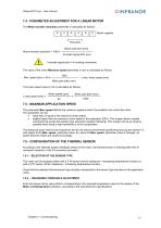
CINFRANOR7.4 - PARAMETER ADJUSTMENT FOR A LINEAR MOTOR The Motor encoder resolution parameter is calculated as follows: Motor magnets Pole pitch Motor pole pitch (mm) Motor encoder resolution = 1000 x Encoder signal pitch (pm) 1 encoder signal pitch = 4 counting increments The value of the motor Maximum speed parameter in rpm is calculated as follows: Motor pole pitch (mm) The linear speed value in m/s is calculated as follows: Motor speed (rpm) Motor pole pitch (mm) The parameter Max. speed defines the maximum speed at which the amplifier can control the motor. • lower than or equal to the maximum...
Open the catalog to page 13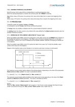
7.6.3 – WARNING THRESHOLD ADJUSTMENT Enter the sensor ohmic value (kOhm) corresponding to a warning temperature value. When the warning temperature is reached, the red front panel LED "ERROR" is blinking. Note: When using a CTN sensor, the warning ohmic value will be higher than or equal to the triggering ohmic value. When using a CTP sensor, the warning ohmic value will be lower than or equal to the triggering ohmic value. 7.7 - I2t PROTECTION 2 selection modes are available: Fusing or Limiting. It is advisable to use the Fusing mode during commissioning phases. In Fusing mode, the amplifier...
Open the catalog to page 14All Infranor Group catalogs and technical brochures
 XtrapulsPac_EN
4 Pages
 SMTBSi-2Tz_en_2.1
43 Pages
 PacSimBox_d_1
1 Page
 Pac-SF01_flyer_en_18.02
4 Pages
 Pac_User_1.2.1.218
253 Pages
 Pac_Templates_en_1.9
27 Pages
 Pac_STO_Installation_en_2.2
13 Pages
 Pac_SF01_operating_en_1.6
63 Pages
 Pac_SF01_EN
4 Pages
 Pac_Installation_en_2.23
82 Pages
 Pac_flyer_en_17.12
4 Pages
 Option_CT_EMF
6 Pages
 MOVINOR_LH055_LH086_LH097_LH142
23 Pages
 ma_series
6 Pages
 GemSafeTorqueOff_en_1.1
12 Pages
 CD1pm_e_1.2(old)
18 Pages
 CD1pInst_e_7.2(old)
35 Pages
 CD1kInst_e_4.1(old)
40 Pages
 CD1k_CANopenProtocol_e_1.3(old)
86 Pages
 CD1a_e_7.1(old)
45 Pages
 Catalogue gamme SMT-BD1
11 Pages
 BM20A(F)v3_0
20 Pages
 BM20A(D)v3_0
20 Pages
 BF400(GB)v2_2
21 Pages
 BF400(D)v2_2
21 Pages
 BF230(GB)v2_0
23 Pages
 BF230(F)v2_0
23 Pages
 BD2m_e_2.2
69 Pages
 BD2m(GB)2.0
70 Pages
 BD2_e_3.2
53 Pages
 BD2(GB)3.1
53 Pages
 BD2(D)3.1
54 Pages
 Movinor_LH_e
4 Pages
 ma_series
6 Pages
 BD1t(GB)3.1
81 Pages
 BD1t(F)3.0
85 Pages
 BD1pInst(GB)3.0
25 Pages
 BD1pInst(F)3.0
23 Pages
 BD1pInst(D)3.0
24 Pages
 BD1pCD1pUse_e_2.4
57 Pages
 BD1m(GB)5.0
58 Pages
 BD1m(F)5.0
57 Pages
 BD1m(D)v3_3
64 Pages
 BD1k(GB)2.1
35 Pages
 BD1k(F)2.1
36 Pages
 BD1j(GB)v2_41
19 Pages
 BD1j(F)v2_4
21 Pages
 BD1i(GB)v2_21
23 Pages
 BD1i(F)v2_2
27 Pages
 BD1h(F)3.0
65 Pages
 BD1h(D)3.0
59 Pages
 BD1g(GB)v3_0
28 Pages
 BD1g(F)v3_0
28 Pages
 BD1a400(GB)v2_3
43 Pages
 BD1a400(F)v2_3
44 Pages
 BD1a400(D)v2_3
45 Pages
 BD1(GB)7.1_noPW
45 Pages
 BD1(GB)7.1
45 Pages
 BD1(F)7.1_noPW
47 Pages
 BD1(F)7.1
47 Pages
 BD1(D)7.1
45 Pages
 BD1 Katalog
11 Pages
 Easy_User_5.0.1.60.2
190 Pages
 01ma_smv_e_01953
40 Pages
 PacHP-SF_Flyer_en_23.06
4 Pages
 IRD_User_Manual_en_1.2.XX.54.rev_b
216 Pages
 PacHP_User_en_1.2.8.100.b
280 Pages
 PacHP_SF02_operating_en_1.6
103 Pages
 PacHP_SF01_operating_en_2.0
63 Pages
 PacHP_Installation_en_2.9
91 Pages
 PacHP_Series_Brochure
8 Pages
 PacHP_Flyer_us_20.10
4 Pages
 IRD_Installation_en_1.5
42 Pages
 Easy_STO_en_1.4
14 Pages
 Easy_DB_STO_en_1.2
14 Pages
 Easy_DB_Installation_en_1.4
36 Pages
 CD1pmInst_en_8.15
40 Pages
 CD1k_CANopenProtocol_en_2.10.1.1
108 Pages
 CD1pm_ProfibusProtocol_en_1.5
50 Pages
 CD1kUser_en_2.3
26 Pages
 CD1a_en_8.17
62 Pages
 CD1kInst_en_5.16
46 Pages
 CD1_STO_en_1.8
16 Pages
 CD1_flyer_en_14.09
4 Pages
 Braking_Resistors_en_1.5
10 Pages
 XtracontrolDC2_EN
4 Pages
 Flyer_VisiTouchCNC_EN_V1.1-1
2 Pages
 XtraforsWashdown_EN-2024
2 Pages
 DataSheet_CybIO_CNC_V1.0
6 Pages
 XtraforsPrime_EN-2024
2 Pages
 XtraforsMSS_EN
4 Pages
 XtraforsMSA_EN_2024
2 Pages
 XtraforsEx_EN-2024
2 Pages
 XtraforsBR_EN-2024
2 Pages
 XtraforsBL_EN-2024
2 Pages
 XtraforsBC-ed01-vs3
4 Pages
 Manual_XtraforsPrime
46 Pages
 Drawing_1
1 Page
 Datasheet_MSS
5 Pages
 Datasheet_2
2 Pages
 Datasheet_1
4 Pages
 BLSBLT_series
2 Pages
 BL220221
2 Pages
 BL270
BL2702 Pages
 BL190
BL1902 Pages
 bl100_series
6 Pages
 bl40_series
6 Pages
 BL30
BL302 Pages
 2019-01_XtraforsFP-DSL_FR
4 Pages
 Movinor_T_EN
4 Pages
 Movinor_N_EN
4 Pages
 Movinor_Low_Voltage_EN
4 Pages
 Manual Movinor T 03-2026
46 Pages
 Manual Movinor N 03-2026
63 Pages
 XtrapulsEasy™ AC servo-drive
4 Pages
 XtrapulsCD1 AC servo-drives
4 Pages
 CybIO
CybIO6 Pages
 AC SERVOMOTORS
2 Pages
 Movinor® N AC Servomotors
4 Pages






Archived catalogs
 AN_CD1ak_AbsoluteEncoder_en_2.0
10 Pages
 AN_CD1ak_SinCosTracks_e_1.0
7 Pages
 AN_CD1pm_AbsoluteEncoder_en_2.0
10 Pages
 AN_CD1pm_SinCosTracks_e_1.0
7 Pages
 AN_DC_bus_interfacing_en_1.3
5 Pages
 CD1_EC_conformity_24.05
1 Page
 CD1_STO_conformity_19.02
2 Pages
 EtherCAT Interface_en_1.3
20 Pages
 Easy_EC_Conformity_24_10
1 Page
 GDPS_EC_conformity_24.07
1 Page
 IRD_EC_Conformity_25.03
1 Page
 PacHP_TÜV_certificate_25.07
2 Pages
 BD1c(F)v2_01
19 Pages
 BD1c(GB)v2_01
19 Pages
 BD1d(F)v2_01
25 Pages
 BD1d(GB)v2_01
25 Pages
 BD1e(F)v2_01
22 Pages
 BD1f(F)v2_01
17 Pages
 BD1f(GB)v2_01
18 Pages
 Pac_EC_conformity_25.04
1 Page




















