
- Catalogs
- Infranor Group
- CD1pm_ProfibusProtocol_en_1.5


CD1pm_ProfibusProtocol_en_1.5

CD1pm_ProfibusProtocol_en_1.5
This technical manual provides guidance on the PROFIBUS Communication Profile for the INFRANOR XtrapulsCD1-pm drive, focusing on hardware version 2.0 and firmware from version 52B.68. It advises consulting the XtrapulsCD1-pm Installation and User Guides for installation and commissioning.
Emphasizes the importance of reading all instructions before operating the amplifiers. Maintenance should be performed by skilled technicians. Compliance with standards and CE approval depends on following the amplifier manuals' recommendations.
INFRANOR products are categorized under WEEE Category 9. The document outlines the company's membership in RECYLUM for WEEE recycling in France and provides disposal instructions per the 2002/96/EC directive.
Amplifiers are designed to resist electrostatic discharges, but proper storage and handling are crucial to prevent damage. Guidelines are provided to minimize ESD risks.
Details waste categorization and disposal instructions for packaging, documents, mechanics, heatsinks, and electronic components, emphasizing recycling and adherence to regional regulations.
The manual is structured into chapters covering PROFIBUS communication, operation, and parameter setting. Key sections include PPO message configuration, parameter setting examples, global control, and detailed operation modes such as position and speed/torque modes.
- Chapter 1 - PROFIBUS Communication: Discusses PPO messages, configuration, parameter setting, and global control.
- Chapter 2 - PROFIBUS Operation: Covers communication, position mode, speed/torque mode, and driving of the positioner.
- Chapter 3 - Parameter Setting: Provides a comprehensive list and description of parameters, including motor, current, speed modulation, and positioner parameters.
INFRANOR reserves the right to change any information without notice and disclaims responsibility for damages due to improper handling or incorrect descriptions.
Outlines parameters for encoder output and input, motor feedback selection, and the use of Hall Effect Sensors. Discusses motor phasing and the use of SinCos tracks for motor feedback.
Describes the Profibus communication system as a master-slave setup, with the INFRANOR® positioner acting as a slave. Key parameters include the amplifier address on the bus, communication speed, and configuration set in the PLC (master).
PPO messages consist of PKW and PZD modules, cyclically transferred by the PROFIBUS DP Data_Exchange function. Details the structure and function of these messages, including the use of SFC14 and SFC15 functions in STEP7® software.
Configuration of PPO types is typically provided by the GSD file but can be manually defined. Provides examples of parameter setting and explains communication rules for instruction/reply between master and slave.
The positioner is controlled via Profibus using the PZD data area. Details the control word structure, input commands, and status indicators for position mode operation.
Outlines the control process for the positioner, including enabling and disabling procedures. Describes the OFF1, OFF2, and OFF3 functions for disabling the motor.
Feedback is provided through the HIW in the PZD area, with specific bits indicating the running sequence and programmable logic outputs.
Includes diagrams illustrating the positioner behavior during operation, showing actions possible when the positioner is in 'Operation enabled' status.
Details the control word and status word for speed and torque modes, with specific bits indicating operational conditions and errors.
Provides a comprehensive list of parameters, including motor pole pairs, resolver shift, current limits, speed modulation, and more.
Explains how to change the PZD data mapping for input commands and feedback.
Emphasizes the importance of checking the positioner status to ensure command execution and provides examples of enabling sequences.
Outlines various parameters necessary for the operation of synchronous motors and positioners, including motor pole pairs, phase order, and position sensor offset.
Essential parameters for motor operation include motor pole pairs, phase order, and position sensor offset.
Defines parameters related to current limitations, including stop current limit, maximum current, rated current, and I2t mode.
Speed modulation parameters allow for dynamic adjustment of motor speed during operation.
Details on current/voltage rating identification and digital PI regulators for D-Q current loops.
Parameters such as positioner mode, maximum speed, motor rotation direction, and acceleration ramp are discussed.
Explains the structure of the regulator used in the XtrapulsCD1-pm, including proportional and integral gains for speed and position loops.
Identifies motor and load parameters to calculate regulator gain parameters.
Emphasizes the importance of executing certain procedures with the positioner disabled and ensuring safety during motor operations.
- Forward Acceleration Gain (PNU 737): Defines the feedforward acceleration amplitude to reduce following error during motor acceleration and deceleration.
- Feedforward Speed 2 Gain (PNU 738): Combines damping speed gain and feedforward friction gain to mitigate load viscous friction effects.
- Speed Loop Damping Gain (PNU 739): Used to achieve maximum servo loop stiffness.
- Position Resolution (PNU 740): Defines position increments per motor revolution.
- Position Following Error Threshold (PNU 741): Triggers an error when position deviation exceeds this value.
- Positioner Configuration (PNU 742): Includes settings for limit switches, speed limitations, and profile types.
- Encoder Output Resolution (PNU 750): Defines encoder resolution, limited by maximum application speed.
- Encoder Input Zero Mark Pitch (PNU 751): Determines encoder pulse count between Zero Mark signals for protection.
- Manual Motion Speed (PNU 760): Speed parameter in rpm, limited by maximum speed settings.
- Acceleration and Deceleration Ramps (PNU 761, 762): Define time for acceleration and deceleration at maximum speed.
- Homing Configuration (PNU 766): Configures manual homing settings.
- Position Input Command (PNU 767): Defines position input for manual motion in absolute or relative mode.
- Positioner Error Code (PNU 773): Provides error codes for various positioner faults.
- Power Stage Faults (PNU 778): Lists potential power stage errors and their bit representations.
- Sequence Control (PNU 782): Manages sequence validity and type (positioning, homing, etc.).
- Position in Sequence (PNU 783): Defines position for sequences, with variations based on resolution.
Provides detailed information on various parameters used in the XtrapulsCD1-pm Profibus Communication Profile for controlling motor sequences.
Defines the ramp times for positioning, speed, and torque sequences.
Specifies delay at the end of positioning, constant speed motion time, or timeout for homing sequences.
Manage sequence transitions and conditional jumps.
Defined by input status, with specific bits indicating which inputs must be set to 0 or 1.
Programmable logic outputs control the effect on outputs during sequences.
Define torque as a percentage of maximum current and speed as a percentage of max speed.
Provide readings from analog and logic inputs, with specific configurations for input and output polarities.
Allows modification of feedback signals from PZD3 to PZD6.
Provide descriptions for various faults, including EEPROM checksum errors, homing timeouts, power overvoltage, and motor overtemperature.
Identifies fault codes such as current sensor offset, overcurrent, and undervoltage.
Includes PZD Command Mapping and Regulator Parameters.
Parameters for gain calculation and error protection modes.
Includes Absolute Encoder Settings and Position Initialization.
Includes SinCos Input Error Compensation and Cogging Torque procedures.
Catalog excerpts
XtrapulsCD1-pm Profibus Communication Profile PROFIBUS Communication Profile XtrapulsCD1-pm Profibus Communication Profile
Open the catalog to page 1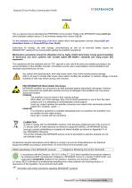
XtrapulsCD1-pm Profibus Communication Profile ! This is a general manual describing the PROFIBUS Communication Profile of the INFRANOR XtrapulsCD1-pm drive (hardware release version 2.0 and firmware release from version 52B.68). For the installation and commissioning of the drive, please refer to the appropriate manuals (XtrapulsCD1-pm Installation Guide and XtrapulsCD1pm User Guide). Instructions for storage, use after storage, commissioning as well as all technical details require the MANDATORY reading of the manual before getting the amplifiers operational. Maintenance procedures should be...
Open the catalog to page 2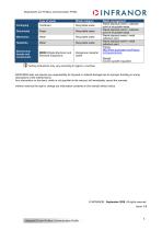
XtrapulsCD1-pm Profibus Communication Profile Waste category Recyclable waste Recyclable waste Recyclable waste Recyclable waste Electronical boards and components WEEE (Waste Electronic and Electrical Equipment) Dangerous industrial waste Waste management Waste disposal centre / collection point of recyclable waste Waste disposal centre / collection point of recyclable waste Waste disposal centre / metal collection point Waste disposal centre / metal collection point France: http://www.ecosystem.eco/fr/sousrubrique/solutions Abroad: Country-specific regulation Sorting instructions may vary...
Open the catalog to page 3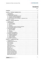
XtrapulsCD1-pm Profibus Communication Profile Contents PAGE
Open the catalog to page 5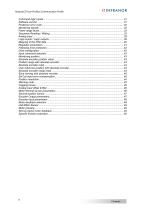
XtrapulsCD1-pm Profibus Communication Profile
Open the catalog to page 6
XtrapulsCD1-pm Profibus Communication Profile The Profibus communication is a master-slave communication. The INFRANOR® positioner is a slave positioner and the only important parameter to be defined for the communication is the amplifier address on the bus. All other parameters (communication speed, configuration, communication parameters) are defined in the PLC (master) and will be automatically sent to the positioner: - the available communication speeds are: 9,6 KB, 19,2 KB, 93,72 KB, 187,5 KB, 500 KB, 1,5 MB, 3 MB, 6 MB, 12 MB and will be automatically detected by the positioner. - the configuration...
Open the catalog to page 7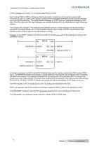
XtrapulsCD1-pm Profibus Communication Profile A PPO message can contain 1 or 2 modules called PKW and PZD. Each module (PKW or PZD) is defined as input-output and is consistant over the whole module length. The communication is made by the reading or writing of PPO messages (the PKW and PZD modules are input and output at the same time). The master sends a message by a PPO-write and receives a message by PPOread. The PPO-write and PPO-read messages are cyclically transferred by the PROFIBUS DP Data_Exchange function. The modules are consistant. This means that the different words of a same message...
Open the catalog to page 8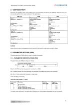
XtrapulsCD1-pm Profibus Communication Profile Normally, the identifiers of the various PPO types are automatically provided by the GSD file. Otherwise, they can be manually defined with values indicated in the table below: The reply code mentioned in the table above contains the normal replies associated with the instructions. Chapter 1 - Profibus Communication
Open the catalog to page 9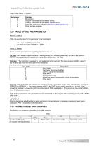
XtrapulsCD1-pm Profibus Communication Profile Reply codes (slave -> master): Chapter 1 - Profibus communication
Open the catalog to page 10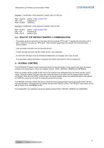
XtrapulsCD1-pm Profibus Communication Profile Example 1: modification of the sequence 2 speed value at 1000 rpm. Example 2: modification of the sequence 5 position value at 200. - The master sends an instruction to the slave with the message "PPO write". It repeats this instruction until it gets a reply from the slave by "PPO read". This procedure guarantees the operator the instruction/reply communication. - Just one single instruction can be executed at once. - A slave provides the reply until the master sends a new instruction. - An instruction (8 bytes) must be completely transferred in a...
Open the catalog to page 11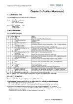
XtrapulsCD1-pm Profibus Communication Profile The positioner is driven by Profibus with the PZD data area. Master -> slave (PLC -> positioner): Slave -> master (positioner -> PLC): Note: For switching from "Profibus" mode to local mode or vice versa, the positioner must be disabled. The input command is contained in HSW (2nd word of PZD - PPO write). For the positioner operation mode (bit 6 of the control word) PZD2 has got the following meaning. Bits 0 to 7: number of the sequence to be executed. Bits 8 to 15: logic inputs (bits 0 to 7). These inputs are used for the sequence start (or stop)...
Open the catalog to page 12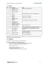
XtrapulsCD1-pm Profibus Communication Profile Note: When the motor reaches a limit switch, the following error is activated (bit 8) and the positioner fault is not activated (bit 3). The motor remains enabled. The feedback is included in HIW (2nd word of PZD - PPO read). In Position mode, PZD2 has got the following meaning: Bits 0 to 7 of the HIW: number of the running sequence (otherwise 0xFF). Bits 8 to 15 of the HIW: programmable logic outputs (0 to 7). PZD3 contains the current monitor in the motor. PZD4 contains the motor speed. PZD5 (MSB) and PZD6 (lSb) contain the motor position. Chapter...
Open the catalog to page 13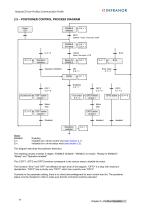
XtrapulsCD1-pm Profibus Communication Profile 2.5 – POSITIONER CONTROL PROCESS DIAGRAM Power ON ENABLE inhibited OFF1 control = xxxx x1xx xxxx xxx0 ENABLE not ready C.3 = 0 Operation inhibition control xxxx x1xx xxxx x110 Ready for ENABLE Operation inhibited Motor stop disabled Operation enabled Enabling. Indicates bit n of the control word (see section 2.1). Indicates bit n of the status word (see section 2.3). This diagram describes the positioner behaviour: The enabling process includes 5 stages: "ENABLE inhibited", "ENABLE not ready", "Ready for ENABLE", "Ready" and "Operation enabled". The...
Open the catalog to page 14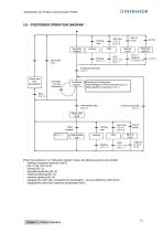
XtrapulsCD1-pm Profibus Communication Profile 2.6 – POSITIONER OPERATION DIAGRAM Operation enabled Drive task over Homing over Electronic gearing Manual move Brake with max. deceleration Positioner function Execution of a sequence Acknowledgment of the command by S.12 When position is reached, S.10 = 1 Continue drive task C.5 = 1 Brake with ramp Intermediate stop Manual move Homing over When the positioner is in "Operation enabled" status, the following actions are possible: - starting a sequence execution (bit 6), - jog+ or jog- (bit 8 or 9), - homing (bit 11), - absolute positioning (bit 12),...
Open the catalog to page 15All Infranor Group catalogs and technical brochures
 XtrapulsPac_EN
4 Pages
 SMTBSi-2Tz_en_2.1
43 Pages
 PacSimBox_d_1
1 Page
 Pac-SF01_flyer_en_18.02
4 Pages
 Pac_User_1.2.1.218
253 Pages
 Pac_Templates_en_1.9
27 Pages
 Pac_STO_Installation_en_2.2
13 Pages
 Pac_SF01_operating_en_1.6
63 Pages
 Pac_SF01_EN
4 Pages
 Pac_Installation_en_2.23
82 Pages
 Pac_flyer_en_17.12
4 Pages
 Option_CT_EMF
6 Pages
 MOVINOR_LH055_LH086_LH097_LH142
23 Pages
 ma_series
6 Pages
 GemSafeTorqueOff_en_1.1
12 Pages
 CD1pm_e_1.2(old)
18 Pages
 CD1pInst_e_7.2(old)
35 Pages
 CD1kInst_e_4.1(old)
40 Pages
 CD1k_CANopenProtocol_e_1.3(old)
86 Pages
 CD1a_e_7.1(old)
45 Pages
 Catalogue gamme SMT-BD1
11 Pages
 BM20A(F)v3_0
20 Pages
 BM20A(D)v3_0
20 Pages
 BF400(GB)v2_2
21 Pages
 BF400(D)v2_2
21 Pages
 BF230(GB)v2_0
23 Pages
 BF230(F)v2_0
23 Pages
 BD2m_e_2.2
69 Pages
 BD2m(GB)2.0
70 Pages
 BD2_e_3.2
53 Pages
 BD2(GB)3.1
53 Pages
 BD2(D)3.1
54 Pages
 Movinor_LH_e
4 Pages
 ma_series
6 Pages
 BD1t(GB)3.1
81 Pages
 BD1t(F)3.0
85 Pages
 BD1pInst(GB)3.0
25 Pages
 BD1pInst(F)3.0
23 Pages
 BD1pInst(D)3.0
24 Pages
 BD1pCD1pUse_e_2.4
57 Pages
 BD1m(GB)5.0
58 Pages
 BD1m(F)5.0
57 Pages
 BD1m(D)v3_3
64 Pages
 BD1k(GB)2.1
35 Pages
 BD1k(F)2.1
36 Pages
 BD1j(GB)v2_41
19 Pages
 BD1j(F)v2_4
21 Pages
 BD1i(GB)v2_21
23 Pages
 BD1i(F)v2_2
27 Pages
 BD1h(F)3.0
65 Pages
 BD1h(D)3.0
59 Pages
 BD1g(GB)v3_0
28 Pages
 BD1g(F)v3_0
28 Pages
 BD1a400(GB)v2_3
43 Pages
 BD1a400(F)v2_3
44 Pages
 BD1a400(D)v2_3
45 Pages
 BD1(GB)7.1_noPW
45 Pages
 BD1(GB)7.1
45 Pages
 BD1(F)7.1_noPW
47 Pages
 BD1(F)7.1
47 Pages
 BD1(D)7.1
45 Pages
 BD1 Katalog
11 Pages
 Easy_User_5.0.1.60.2
190 Pages
 01ma_smv_e_01953
40 Pages
 PacHP-SF_Flyer_en_23.06
4 Pages
 IRD_User_Manual_en_1.2.XX.54.rev_b
216 Pages
 PacHP_User_en_1.2.8.100.b
280 Pages
 PacHP_SF02_operating_en_1.6
103 Pages
 PacHP_SF01_operating_en_2.0
63 Pages
 PacHP_Installation_en_2.9
91 Pages
 PacHP_Series_Brochure
8 Pages
 PacHP_Flyer_us_20.10
4 Pages
 IRD_Installation_en_1.5
42 Pages
 Easy_STO_en_1.4
14 Pages
 Easy_DB_STO_en_1.2
14 Pages
 Easy_DB_Installation_en_1.4
36 Pages
 CD1pmUser_en_4.2
55 Pages
 CD1pmInst_en_8.15
40 Pages
 CD1k_CANopenProtocol_en_2.10.1.1
108 Pages
 CD1kUser_en_2.3
26 Pages
 CD1a_en_8.17
62 Pages
 CD1kInst_en_5.16
46 Pages
 CD1_STO_en_1.8
16 Pages
 CD1_flyer_en_14.09
4 Pages
 Braking_Resistors_en_1.5
10 Pages
 XtracontrolDC2_EN
4 Pages
 Flyer_VisiTouchCNC_EN_V1.1-1
2 Pages
 XtraforsWashdown_EN-2024
2 Pages
 DataSheet_CybIO_CNC_V1.0
6 Pages
 XtraforsPrime_EN-2024
2 Pages
 XtraforsMSS_EN
4 Pages
 XtraforsMSA_EN_2024
2 Pages
 XtraforsEx_EN-2024
2 Pages
 XtraforsBR_EN-2024
2 Pages
 XtraforsBL_EN-2024
2 Pages
 XtraforsBC-ed01-vs3
4 Pages
 Manual_XtraforsPrime
46 Pages
 Drawing_1
1 Page
 Datasheet_MSS
5 Pages
 Datasheet_2
2 Pages
 Datasheet_1
4 Pages
 BLSBLT_series
2 Pages
 BL220221
2 Pages
 BL270
BL2702 Pages
 BL190
BL1902 Pages
 bl100_series
6 Pages
 bl40_series
6 Pages
 BL30
BL302 Pages
 2019-01_XtraforsFP-DSL_FR
4 Pages
 Movinor_T_EN
4 Pages
 Movinor_N_EN
4 Pages
 Movinor_Low_Voltage_EN
4 Pages
 Manual Movinor T 03-2026
46 Pages
 Manual Movinor N 03-2026
63 Pages
 XtrapulsEasy™ AC servo-drive
4 Pages
 XtrapulsCD1 AC servo-drives
4 Pages
 CybIO
CybIO6 Pages
 AC SERVOMOTORS
2 Pages
 Movinor® N AC Servomotors
4 Pages






Archived catalogs
 AN_CD1ak_AbsoluteEncoder_en_2.0
10 Pages
 AN_CD1ak_SinCosTracks_e_1.0
7 Pages
 AN_CD1pm_AbsoluteEncoder_en_2.0
10 Pages
 AN_CD1pm_SinCosTracks_e_1.0
7 Pages
 AN_DC_bus_interfacing_en_1.3
5 Pages
 CD1_EC_conformity_24.05
1 Page
 CD1_STO_conformity_19.02
2 Pages
 EtherCAT Interface_en_1.3
20 Pages
 Easy_EC_Conformity_24_10
1 Page
 GDPS_EC_conformity_24.07
1 Page
 IRD_EC_Conformity_25.03
1 Page
 PacHP_TÜV_certificate_25.07
2 Pages
 BD1c(F)v2_01
19 Pages
 BD1c(GB)v2_01
19 Pages
 BD1d(F)v2_01
25 Pages
 BD1d(GB)v2_01
25 Pages
 BD1e(F)v2_01
22 Pages
 BD1f(F)v2_01
17 Pages
 BD1f(GB)v2_01
18 Pages
 Pac_EC_conformity_25.04
1 Page




















