
- Catalogs
- Infranor Group
- CD1pm_e_1.2(old)


CD1pm_e_1.2(old)

CD1pm_e_1.2(old)
- Terminal Configuration: Displays information over 4 lines with 20 characters each, using RS-232 with a baud rate of 19200, 1 stop bit, no parity, and VT-100 protocol.
- Positioner Configuration: Communication via VT-100 requires the amplifier to be set to hexadecimal address 7E using DIP micro-switches.
- Main Menu: Allows actions using keys 1 to 4, such as displaying motor position, modifying sequences, starting sequences, and moving the motor to specific positions.
- Position Display: Arrow keys enable motor movement when the ENABLE signal is active, with designated keys to stop and confirm the stop.
- Sequence Modification: Operators can modify sequence position or speed by entering the sequence number and new values.
- Sequence Execution: When no sequence is executing and the ENABLE signal is active, operators can enter a sequence number to execute it.
- Motion: When no sequence is executing and the ENABLE signal is active, operators can enter a position for the motor to reach.
Catalog excerpts
SERVO DRIVES & MOTION CONTROL
Open the catalog to page 1
! This manual is describing a series of positioning servo amplifiers having output capability for driving AC brushless servo motors. This manual must be used in conjunction with both manuals CD1p-Installation and BD1/CD1pUser Guide of the CD1-p (Profibus) amplifier and cannot be dissociated from it. The conditions and recommendations of use as well as the responsibility and warranty restrictions mentioned in both manuals above are also valid for the present amplifier version CD1-pm. ©INFRANOR, January 2004. All rights reserved Issue: 1.2
Open the catalog to page 3
The CD1-pm positioner is an extended version of the CD1-p positioner. It has got several logic inputs/outputs and can work in the following modes: ❖ Profibus mode with hardware addressing, The selection of the various operation modes is made by means of micro-switches accessible by the operator (see chapter 6). This mode is activated by the 00 micro-switches selection. This operation mode is the same as the one of the CD1-p positioner. The positioner Profibus address is saved into a non volatile memory (EEPROM). This EEPROM can be modified via Profibus (message Set_Slave_Add) by a Profibus master...
Open the catalog to page 6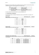
CINFRANOR By default, the inputs are Profibus inputs (compatibility with the CD1-p positioner). Some bits of the positioner configuration word (PNU 742) allow the selection of the hardware inputs. Chapter 1 - Operation mode
Open the catalog to page 7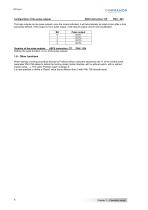
The logic outputs can be pulse outputs: once the output activated, it will automatically be reset at zero after a time previously defined. If this output is not a pulse output, it will keep its status until its next modification. Defines the pulse duration, in ms, of the pulse outputs. When starting a homing procedure directly by Profibus without using the sequences (bit 11 of the control word), parameter PNU 766 allows to define the homing mode (motion direction with or without switch, with or without marker pulse, ...). The value "Position reset" is always 0. It is now possible to define a...
Open the catalog to page 8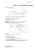
Chapter 2 – Optocoupled logic inputs 2.1 - Diagram of the logic inputs +5 V Logic inputs The input voltage corresponding to level 1 must remain between 18 V and 30 V. 2.2 - Specifications of the optocoupled logic inputs 2.2.1 - Dedicated inputs (number = 2) START input: This input allows to start the sequence which number is defined by the programmable inputs. The level of this input will be taken into account after the end of the former sequence. This signal can be disabled before the end of the sequence. Logic inputs combinations 1.5 msec. min START STOP input: This input allows to stop the...
Open the catalog to page 9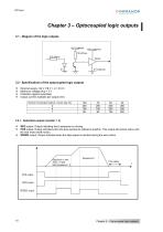
3.2 - Specifications of the optocoupled logic outputs ❖ External supply +24 V (18 V < U < 30 V) ❖ Maximum voltage drop = 2 V ❖ Protection against overloads ❖ Output current available per output (mA) 3.2.1 - Dedicated outputs (number = 3) ❖ SEQ output: Output indicating that a sequence is running. ❖ POS output: Output activated when the axis reaches its reference position. This output will remain active until the next motor shaft motion. ❖ SPEED output: Output activated when the step speed is reached during the axis motion. Chapter 3 - Optocoupled logic outputs
Open the catalog to page 10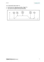
3.2.2 - Programmable outputs (number = 4) Programmable status: "High" status - "Low" status - "Toggle" status. Various triggering types: BEGIN, SPEED, POS, HOLD, END. These outputs can be triggered once a programmed sequence. BEGIN : Sequence begin SPEED : Speed reached POS : Pre-defined position reached HOLD : Arrival at reference position Chapter 3 – Optocoupled logic outputs
Open the catalog to page 11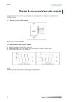
Two pulse channels "A" and "B" in quadrature with one marker pulse "Z" per revolution are available on the CD1-pm positioner. ❖ 4 differential signals A (/A), B (/B) in quadrature ❖ 2 differential signals Z (/z): One "marker pulse" per revolution - Duration = [Period (A)/4], ❖ Non-modifiable resolution: 1024 periods/rev. (front view of the motor shaft) (front view of the motor shaft) The use of a shielded cable for the encoder signals is MANDATORY. Chapter 4 - Incremental encoder outputs
Open the catalog to page 12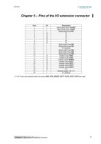
Pins of the I/O extension connector +24 V input only required when the outputs SEQ, POS, SPEED, OUT1, OUT2, OUT3, OUT4 are used.
Open the catalog to page 13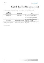
A DIP micro-switch, accessible by the operator, allows the selection of the various operation modes. Chapter 6 - Selection of the various modes
Open the catalog to page 14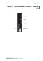
Chapter 7 – Location of the I/O extension connector (X2) Chapter 7 – Location of the I/O extension connector (X2)
Open the catalog to page 15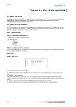
SERVO DRIVES & MOTION CONTROL The parameter setting of the CD1-pm amplifier can be made by means of the PC software, but also by means of the serial link, by using the RS-232 protocol as well as the ASCII instructions described in the manual "INFRANOR drives parameter setting instructions". A VT-100 terminal can be connected to the serial link of the amplifier (X5 connector). The operator can use this terminal to display the axis position, to modify or execute pre-programmed motion sequences, to move the axis towards an absolute position or to control a JOG movement. 8.2.1 - CONFIGURATION8.2.1.1...
Open the catalog to page 16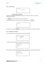
The arrow keys ENABLE signal is activated. The allow to move the motor (Jog+ or Jog-), when the key allows the operator to go back to the main menu. In this window, the operator can stop the motor (if it is rotating) by pressing the The operator must press the key for confirming the motor stopping or any other key for cancelling. 8.2.2.3 – Modification of a sequence This menu allows the operator to modify position or speed of a given sequence. MODIFY SEQUENCE 1 POSITION 2 SPEED_ The operator at first enters the sequence number (this sequence must exist). The former position is displayed and the...
Open the catalog to page 17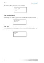
The operator can modify the speed of a give sequence in the same way: MODIFY SPEED Sequence: 1 Pos: 1øøø Speed:_ 8.2.2.4 – Execution of a sequence When the position is not executing any sequence and when the ENABLE signal is activated, the operator can enter the number of a sequence to be executed: 8.2.2.5 - Motion When the positioner is not executing any sequence and when the ENABLE signal is activated, the operator can enter a position to be reached:
Open the catalog to page 18All Infranor Group catalogs and technical brochures
 XtrapulsPac_EN
4 Pages
 SMTBSi-2Tz_en_2.1
43 Pages
 PacSimBox_d_1
1 Page
 Pac-SF01_flyer_en_18.02
4 Pages
 Pac_User_1.2.1.218
253 Pages
 Pac_Templates_en_1.9
27 Pages
 Pac_STO_Installation_en_2.2
13 Pages
 Pac_SF01_operating_en_1.6
63 Pages
 Pac_SF01_EN
4 Pages
 Pac_Installation_en_2.23
82 Pages
 Pac_flyer_en_17.12
4 Pages
 Option_CT_EMF
6 Pages
 MOVINOR_LH055_LH086_LH097_LH142
23 Pages
 ma_series
6 Pages
 GemSafeTorqueOff_en_1.1
12 Pages
 CD1pInst_e_7.2(old)
35 Pages
 CD1kInst_e_4.1(old)
40 Pages
 CD1k_CANopenProtocol_e_1.3(old)
86 Pages
 CD1a_e_7.1(old)
45 Pages
 Catalogue gamme SMT-BD1
11 Pages
 BM20A(F)v3_0
20 Pages
 BM20A(D)v3_0
20 Pages
 BF400(GB)v2_2
21 Pages
 BF400(D)v2_2
21 Pages
 BF230(GB)v2_0
23 Pages
 BF230(F)v2_0
23 Pages
 BD2m_e_2.2
69 Pages
 BD2m(GB)2.0
70 Pages
 BD2_e_3.2
53 Pages
 BD2(GB)3.1
53 Pages
 BD2(D)3.1
54 Pages
 Movinor_LH_e
4 Pages
 ma_series
6 Pages
 BD1t(GB)3.1
81 Pages
 BD1t(F)3.0
85 Pages
 BD1pInst(GB)3.0
25 Pages
 BD1pInst(F)3.0
23 Pages
 BD1pInst(D)3.0
24 Pages
 BD1pCD1pUse_e_2.4
57 Pages
 BD1m(GB)5.0
58 Pages
 BD1m(F)5.0
57 Pages
 BD1m(D)v3_3
64 Pages
 BD1k(GB)2.1
35 Pages
 BD1k(F)2.1
36 Pages
 BD1j(GB)v2_41
19 Pages
 BD1j(F)v2_4
21 Pages
 BD1i(GB)v2_21
23 Pages
 BD1i(F)v2_2
27 Pages
 BD1h(F)3.0
65 Pages
 BD1h(D)3.0
59 Pages
 BD1g(GB)v3_0
28 Pages
 BD1g(F)v3_0
28 Pages
 BD1a400(GB)v2_3
43 Pages
 BD1a400(F)v2_3
44 Pages
 BD1a400(D)v2_3
45 Pages
 BD1(GB)7.1_noPW
45 Pages
 BD1(GB)7.1
45 Pages
 BD1(F)7.1_noPW
47 Pages
 BD1(F)7.1
47 Pages
 BD1(D)7.1
45 Pages
 BD1 Katalog
11 Pages
 Easy_User_5.0.1.60.2
190 Pages
 01ma_smv_e_01953
40 Pages
 PacHP-SF_Flyer_en_23.06
4 Pages
 IRD_User_Manual_en_1.2.XX.54.rev_b
216 Pages
 PacHP_User_en_1.2.8.100.b
280 Pages
 PacHP_SF02_operating_en_1.6
103 Pages
 PacHP_SF01_operating_en_2.0
63 Pages
 PacHP_Installation_en_2.9
91 Pages
 PacHP_Series_Brochure
8 Pages
 PacHP_Flyer_us_20.10
4 Pages
 IRD_Installation_en_1.5
42 Pages
 Easy_STO_en_1.4
14 Pages
 Easy_DB_STO_en_1.2
14 Pages
 Easy_DB_Installation_en_1.4
36 Pages
 CD1pmUser_en_4.2
55 Pages
 CD1pmInst_en_8.15
40 Pages
 CD1k_CANopenProtocol_en_2.10.1.1
108 Pages
 CD1pm_ProfibusProtocol_en_1.5
50 Pages
 CD1kUser_en_2.3
26 Pages
 CD1a_en_8.17
62 Pages
 CD1kInst_en_5.16
46 Pages
 CD1_STO_en_1.8
16 Pages
 CD1_flyer_en_14.09
4 Pages
 Braking_Resistors_en_1.5
10 Pages
 XtracontrolDC2_EN
4 Pages
 Flyer_VisiTouchCNC_EN_V1.1-1
2 Pages
 XtraforsWashdown_EN-2024
2 Pages
 DataSheet_CybIO_CNC_V1.0
6 Pages
 XtraforsPrime_EN-2024
2 Pages
 XtraforsMSS_EN
4 Pages
 XtraforsMSA_EN_2024
2 Pages
 XtraforsEx_EN-2024
2 Pages
 XtraforsBR_EN-2024
2 Pages
 XtraforsBL_EN-2024
2 Pages
 XtraforsBC-ed01-vs3
4 Pages
 Manual_XtraforsPrime
46 Pages
 Drawing_1
1 Page
 Datasheet_MSS
5 Pages
 Datasheet_2
2 Pages
 Datasheet_1
4 Pages
 BLSBLT_series
2 Pages
 BL220221
2 Pages
 BL270
BL2702 Pages
 BL190
BL1902 Pages
 bl100_series
6 Pages
 bl40_series
6 Pages
 BL30
BL302 Pages
 2019-01_XtraforsFP-DSL_FR
4 Pages
 Movinor_T_EN
4 Pages
 Movinor_N_EN
4 Pages
 Movinor_Low_Voltage_EN
4 Pages
 Manual Movinor T 03-2026
46 Pages
 Manual Movinor N 03-2026
63 Pages
 XtrapulsEasy™ AC servo-drive
4 Pages
 XtrapulsCD1 AC servo-drives
4 Pages
 CybIO
CybIO6 Pages
 AC SERVOMOTORS
2 Pages
 Movinor® N AC Servomotors
4 Pages






Archived catalogs
 AN_CD1ak_AbsoluteEncoder_en_2.0
10 Pages
 AN_CD1ak_SinCosTracks_e_1.0
7 Pages
 AN_CD1pm_AbsoluteEncoder_en_2.0
10 Pages
 AN_CD1pm_SinCosTracks_e_1.0
7 Pages
 AN_DC_bus_interfacing_en_1.3
5 Pages
 CD1_EC_conformity_24.05
1 Page
 CD1_STO_conformity_19.02
2 Pages
 EtherCAT Interface_en_1.3
20 Pages
 Easy_EC_Conformity_24_10
1 Page
 GDPS_EC_conformity_24.07
1 Page
 IRD_EC_Conformity_25.03
1 Page
 PacHP_TÜV_certificate_25.07
2 Pages
 BD1c(F)v2_01
19 Pages
 BD1c(GB)v2_01
19 Pages
 BD1d(F)v2_01
25 Pages
 BD1d(GB)v2_01
25 Pages
 BD1e(F)v2_01
22 Pages
 BD1f(F)v2_01
17 Pages
 BD1f(GB)v2_01
18 Pages
 Pac_EC_conformity_25.04
1 Page




















