
- Catalogs
- Infranor Group
- CD1kUser_en_2.3


CD1kUser_en_2.3

CD1kUser_en_2.3
XtrapulsCD1-k amplifiers are digital devices for controlling brushless AC motors with position sensors, operating on 230 VAC and 400/480 VAC. They use the CANopen protocol, with parameter settings adjustable via CANopen bus or Visual Drive Setup software through an RS-232 port.
Installation of Parameter Setting Software: Visual Drive Setup software, compatible with Windows, is available for download from the Infranor website for easy parameter configuration.
Checking Hardware Configuration: Standard configuration is for MAVILOR motors, with adjustments for other types detailed in the installation guide.
Powering the Amplifier: Follow the installation guide, ensuring the 24V auxiliary supply is activated before the main power, with a 30-second interval between cycles.
Starting and Adjusting: Connect the RS232 link, power on the amplifier, and launch the software, ensuring proper serial communication settings.
The amplifier includes logic inputs for controls such as inhibit, limit switch, low speed, and index inputs, along with brake control and addressing switch/speed selection.
Error types include system, non-stored, and stored errors, with solutions for issues like motor non-movement and low torque. Regular maintenance is advised.
INFRANOR products fall under WEEE Category 9, requiring disposal according to the 2002/96/EC directive through certified organizations like RECYLUM in France.
Configure the amplifier using Visual Drive Setup software by switching to Local mode or disabling CANopen communication.
Configuration of the Sensor Type: Select sensor type via software, saved in EEPROM. Ensure correct connection and supply voltage for Hall effect sensors.
Selection of the Motor Type: Choose motor from software list to calculate current loop parameters, adjusting Max. and Rated current as needed.
Encoder Counting Protection: Detects pulse counting errors to prevent uncontrolled movements.
Parameter Adjustment for a Linear Motor: Provides calculations for encoder resolution and maximum speed.
Maximum Application Speed: Defines maximum speed to prevent position loop saturation.
Configuration of the Thermal Sensor: Select sensor type and adjust thresholds based on ohmic values.
Two modes: Fusing (disables amplifier at threshold) and Limiting (restricts current to Rated value).
Regulator Parameters: Autotuning calculates speed/position loop parameters, with adjustments in Position mode.
Loop Adjustment with a Vertical Load: Use Limiting mode, initialize gains with motor unloaded, and execute Autotuning at standstill.
Rotation / Counting Direction: Reverse direction using software.
Store parameters in non-volatile EEPROM after adjustments.
Perform motor phasing with Incremental encoder without HES configuration at each power on.
Details motor phasing procedures, emphasizing incremental encoder with HES or absolute Sin/Cos encoder. Adjustable parameters include resolution division ratio and zero pulse origin shift.
Compensation option in amplifier for cogging torque in brushless motors, requiring uncoupled motor and specific settings in Servo loop module.
Describes logic inputs like "INHIBIT," "LIMIT SWITCH," "LOW SPEED," and "INDEX," with functions for deceleration, protection, and homing.
Details error handling, including system, non-stored, and stored errors, with diagnostic steps and corrective actions.
Refers to a separate manual for CANopen communication commissioning.
- Encoder Configuration: Ensure correct supply voltage and grounding for TTL incremental encoders.
- Motor Speed and Encoder Pulse Frequency: Verify motor speed limits based on encoder pulses per revolution.
- Sin/Cos Encoder Configuration: Emphasizes R reference signals and consistent encoder position values.
- Error Handling: Addresses various errors with specific checks and procedures.
- Operation Problems: Includes checks for amplifier status, wiring, and parameter settings.
- Service and Maintenance: Guidelines for replacing amplifiers and ensuring compatibility.
- Controller Gains: Describes gains calculated during auto-tuning.
- Auto-Tuning Procedure: Identifies motor and load characteristics for controller gains.
- Performance Optimization: Options for minimizing following error and position overshoot.
Catalog excerpts
CINFRANOR XtrapulsCD1-k User Guide
Open the catalog to page 1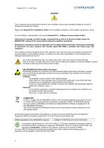
XtrapulsCD1-k – User Guide WARNING ! This is a general manual describing a series of servo amplifiers having output capability suitable for driving AC brushless sinusoidal servo motors. Please see XtrapulsCD1-k Installation Guide for the hardware installation of the amplifier (dimensions, wiring, ...). For the CANopen communication, see manual XtrapulsCD1-k – CANopen Communication Profile. Instructions for storage, use after storage, commissioning as well as all technical details require the MANDATORY reading of the manual before getting the amplifiers operational. Maintenance procedures should...
Open the catalog to page 2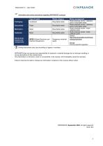
Information and sorting instructions regarding INFRANOR Waste category Recyclable waste Recyclable waste Recyclable waste Recyclable waste Electronical boards and components WEEE (Waste Electronic and Electrical Equipment) Dangerous industrial waste Waste management Waste disposal centre / collection point of recyclable waste Waste disposal centre / collection point of recyclable waste Waste disposal centre / metal collection point Waste disposal centre / metal collection point France: http://www.ecosystem.eco/fr/sousrubrique/solutions Abroad: Country-specific regulation Sorting instructions...
Open the catalog to page 3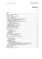
Content PAGE
Open the catalog to page 4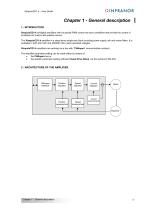
Chapter 1 - General description 1 - INTRODUCTION XtrapulsCD1-k all-digital amplifiers with sinusoidal PWM control are servo amplifiers that provide the control of brushless AC motors with position sensor. The XtrapulsCD1-k amplifier is a stand-alone single-axis block including power supply unit and mains filters. It is available in both 230 VAC and 400/480 VAC mains operated voltages. XtrapulsCD1-k amplifiers are working via a bus with "CANopen" communication protocol. The amplifier parameter setting can be made either by means of: the CANopen bus or the specific parameter setting software...
Open the catalog to page 5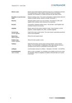
Electric motor Electric device that transforms electrical energy into a mechanical movement. This transformation is often made by means of current commutation. Generally, the movement is a rotation but there are also linear motors. Brushless or synchronous motor Electric brushless motor. The current commutation is electronically made and requires a position sensor (resolver, encoder, Hall sensor...). Absolute position sensor over one revolution. The resolver is often used together with brushless motors because of its robustness. Incremental or absolute position sensor. The encoder is used together...
Open the catalog to page 6
Chapter 2 - Commissioning CAUTION ! Do not make the amplifier parameter setting by means of both Visual Amplifier Setup software and CANopen bus at the same time. 1 - INSTALLATION OF THE PARAMETER SETTING SOFTWARE The Visual Drive Setup software is PC compliant under Windows® 1 and allows an easy parameter setting of the XtrapulsCD1-k amplifier. Please see our website www.infranor.fr for downloading the "Visual Amplifier Setup" software. 2 - CHECKING THE AMPLIFIER HARDWARE CONFIGURATION The standard amplifier configuration is adjusted to MAVILOR motors (resolver sensor with transformation ratio...
Open the catalog to page 7
XtrapulsCDI-k - User Guide This chapter describes the commissioning procedure of the amplifier by means of the " Visual Amplifier Setup" software. • Connect the serial link RS232 between PC and amplifier. • Switch on the amplifier and start the Visual Drive Setup software on the PC, under WINDOWS®. If the message No serial communication found is displayed on the screen, click on OK and check the following points: o The correct RS232 connection between amplifier and PC, o The correct software configuration (Com.port, ...). For a parameter setting of the amplifier via the Visual Drive Setup software:...
Open the catalog to page 8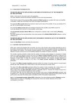
XtrapulsCD1-k – User Guide 4.1.2 - SELECTION OF THE MOTOR TYPE THE MOTOR USED IN THE APPLICATION IS CONTAINED IN THE MOTOR LIST OF THE PARAMETER SETTING SOFTWARE Select, in the motor list, the motor used in the application. The motor selection will start the automatic calculation of the current loop parameters. Check that the values of the parameters Max. current and Rated current are compliant with motor and amplifier. If necessary, modify them according to the motor and amplifier specifications. The parameter Max current defines the maximum output current value of the amplifier. It may vary...
Open the catalog to page 9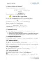
XtrapulsCDI-k - User Guide 4.1.4 - PARAMETER ADJUSTMENT FOR A LINEAR MOTOR The Motor encoder resolution parameter is calculated as follows: Motor magnets Pole pitch Motor pole pitch (mm) Encoder signal pitch (pm) 1 encoder signal pitch = 4 counting incrementsThe value of the motor Maximum speed parameter in rpm is calculated as follows:Max. speed (rpm) = 60 x max. motor speed (m/s) Moto r pole pitch (mm) Motor speed (rpm) Motor pole pitch (mm) 4.1.5 - MAXIMUM APPLICATION SPEED The parameter Max. speed defines the maximum speed at which the amplifier can control the motor. • lower than or equal...
Open the catalog to page 10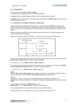
XtrapulsCD1-k – User Guide 4.2 - I2T PROTECTION 2 selection modes are available: Fusing or Limiting. It is advisable to use the Fusing mode during commissioning phases. In Fusing mode, the amplifier is disabled when the current limitation threshold is reached. In Limiting mode, the motor current is only limited at the value defined by the Rated current parameter when the limitation threshold is reached. 4.2.1 - OPERATION OF THE CURRENT LIMITATION IN "FUSING" MODE When the amplifier output RMS current (I2t) reaches 85 % of the rated current, the OK LED is blinking on the amplifier front panel...
Open the catalog to page 11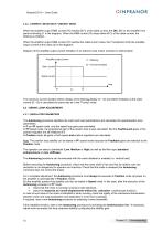
4.2.2 - CURRENT LIMITATION IN "LIMITING" MODE When the amplifier output RMS current (I2t) reaches 85 % of the rated current, the OK LED on the amplifier front panel is blinking (t1 in the diagram). When the RMS current (I2t) drops below 85 % of the rated current, the blinking is inhibited. When the amplifier output RMS current (I2t) reaches the rated current value, the I2t protection limits the amplifier output current at this value (t2 in the diagram). Diagram of the amplifier output current limitation in an extreme case (motor overload or shaft locked): Amplifier output current t1 = Blinking...
Open the catalog to page 12All Infranor Group catalogs and technical brochures
 XtrapulsPac_EN
4 Pages
 SMTBSi-2Tz_en_2.1
43 Pages
 PacSimBox_d_1
1 Page
 Pac-SF01_flyer_en_18.02
4 Pages
 Pac_User_1.2.1.218
253 Pages
 Pac_Templates_en_1.9
27 Pages
 Pac_STO_Installation_en_2.2
13 Pages
 Pac_SF01_operating_en_1.6
63 Pages
 Pac_SF01_EN
4 Pages
 Pac_Installation_en_2.23
82 Pages
 Pac_flyer_en_17.12
4 Pages
 Option_CT_EMF
6 Pages
 MOVINOR_LH055_LH086_LH097_LH142
23 Pages
 ma_series
6 Pages
 GemSafeTorqueOff_en_1.1
12 Pages
 CD1pm_e_1.2(old)
18 Pages
 CD1pInst_e_7.2(old)
35 Pages
 CD1kInst_e_4.1(old)
40 Pages
 CD1k_CANopenProtocol_e_1.3(old)
86 Pages
 CD1a_e_7.1(old)
45 Pages
 Catalogue gamme SMT-BD1
11 Pages
 BM20A(F)v3_0
20 Pages
 BM20A(D)v3_0
20 Pages
 BF400(GB)v2_2
21 Pages
 BF400(D)v2_2
21 Pages
 BF230(GB)v2_0
23 Pages
 BF230(F)v2_0
23 Pages
 BD2m_e_2.2
69 Pages
 BD2m(GB)2.0
70 Pages
 BD2_e_3.2
53 Pages
 BD2(GB)3.1
53 Pages
 BD2(D)3.1
54 Pages
 Movinor_LH_e
4 Pages
 ma_series
6 Pages
 BD1t(GB)3.1
81 Pages
 BD1t(F)3.0
85 Pages
 BD1pInst(GB)3.0
25 Pages
 BD1pInst(F)3.0
23 Pages
 BD1pInst(D)3.0
24 Pages
 BD1pCD1pUse_e_2.4
57 Pages
 BD1m(GB)5.0
58 Pages
 BD1m(F)5.0
57 Pages
 BD1m(D)v3_3
64 Pages
 BD1k(GB)2.1
35 Pages
 BD1k(F)2.1
36 Pages
 BD1j(GB)v2_41
19 Pages
 BD1j(F)v2_4
21 Pages
 BD1i(GB)v2_21
23 Pages
 BD1i(F)v2_2
27 Pages
 BD1h(F)3.0
65 Pages
 BD1h(D)3.0
59 Pages
 BD1g(GB)v3_0
28 Pages
 BD1g(F)v3_0
28 Pages
 BD1a400(GB)v2_3
43 Pages
 BD1a400(F)v2_3
44 Pages
 BD1a400(D)v2_3
45 Pages
 BD1(GB)7.1_noPW
45 Pages
 BD1(GB)7.1
45 Pages
 BD1(F)7.1_noPW
47 Pages
 BD1(F)7.1
47 Pages
 BD1(D)7.1
45 Pages
 BD1 Katalog
11 Pages
 Easy_User_5.0.1.60.2
190 Pages
 01ma_smv_e_01953
40 Pages
 PacHP-SF_Flyer_en_23.06
4 Pages
 IRD_User_Manual_en_1.2.XX.54.rev_b
216 Pages
 PacHP_User_en_1.2.8.100.b
280 Pages
 PacHP_SF02_operating_en_1.6
103 Pages
 PacHP_SF01_operating_en_2.0
63 Pages
 PacHP_Installation_en_2.9
91 Pages
 PacHP_Series_Brochure
8 Pages
 PacHP_Flyer_us_20.10
4 Pages
 IRD_Installation_en_1.5
42 Pages
 Easy_STO_en_1.4
14 Pages
 Easy_DB_STO_en_1.2
14 Pages
 Easy_DB_Installation_en_1.4
36 Pages
 CD1pmUser_en_4.2
55 Pages
 CD1pmInst_en_8.15
40 Pages
 CD1k_CANopenProtocol_en_2.10.1.1
108 Pages
 CD1pm_ProfibusProtocol_en_1.5
50 Pages
 CD1a_en_8.17
62 Pages
 CD1kInst_en_5.16
46 Pages
 CD1_STO_en_1.8
16 Pages
 CD1_flyer_en_14.09
4 Pages
 Braking_Resistors_en_1.5
10 Pages
 XtracontrolDC2_EN
4 Pages
 Flyer_VisiTouchCNC_EN_V1.1-1
2 Pages
 XtraforsWashdown_EN-2024
2 Pages
 DataSheet_CybIO_CNC_V1.0
6 Pages
 XtraforsPrime_EN-2024
2 Pages
 XtraforsMSS_EN
4 Pages
 XtraforsMSA_EN_2024
2 Pages
 XtraforsEx_EN-2024
2 Pages
 XtraforsBR_EN-2024
2 Pages
 XtraforsBL_EN-2024
2 Pages
 XtraforsBC-ed01-vs3
4 Pages
 Manual_XtraforsPrime
46 Pages
 Drawing_1
1 Page
 Datasheet_MSS
5 Pages
 Datasheet_2
2 Pages
 Datasheet_1
4 Pages
 BLSBLT_series
2 Pages
 BL220221
2 Pages
 BL270
BL2702 Pages
 BL190
BL1902 Pages
 bl100_series
6 Pages
 bl40_series
6 Pages
 BL30
BL302 Pages
 2019-01_XtraforsFP-DSL_FR
4 Pages
 Movinor_T_EN
4 Pages
 Movinor_N_EN
4 Pages
 Movinor_Low_Voltage_EN
4 Pages
 Manual Movinor T 03-2026
46 Pages
 Manual Movinor N 03-2026
63 Pages
 XtrapulsEasy™ AC servo-drive
4 Pages
 XtrapulsCD1 AC servo-drives
4 Pages
 CybIO
CybIO6 Pages
 AC SERVOMOTORS
2 Pages
 Movinor® N AC Servomotors
4 Pages






Archived catalogs
 AN_CD1ak_AbsoluteEncoder_en_2.0
10 Pages
 AN_CD1ak_SinCosTracks_e_1.0
7 Pages
 AN_CD1pm_AbsoluteEncoder_en_2.0
10 Pages
 AN_CD1pm_SinCosTracks_e_1.0
7 Pages
 AN_DC_bus_interfacing_en_1.3
5 Pages
 CD1_EC_conformity_24.05
1 Page
 CD1_STO_conformity_19.02
2 Pages
 EtherCAT Interface_en_1.3
20 Pages
 Easy_EC_Conformity_24_10
1 Page
 GDPS_EC_conformity_24.07
1 Page
 IRD_EC_Conformity_25.03
1 Page
 PacHP_TÜV_certificate_25.07
2 Pages
 BD1c(F)v2_01
19 Pages
 BD1c(GB)v2_01
19 Pages
 BD1d(F)v2_01
25 Pages
 BD1d(GB)v2_01
25 Pages
 BD1e(F)v2_01
22 Pages
 BD1f(F)v2_01
17 Pages
 BD1f(GB)v2_01
18 Pages
 Pac_EC_conformity_25.04
1 Page




















