- Catalogs
- Infranor Group
- CD1kInst_e_4.1(old)


CD1kInst_e_4.1(old)

CD1kInst_e_4.1(old)
The CD1-k series are PWM servo drives designed for controlling AC sinusoidal motors with a CANopen interface. They are available in single-axis and three-axis configurations, operating on 230 VAC or 400/480 VAC power supplies. An auxiliary 24VDC supply is required for the DC/DC converter, with specific wiring to maintain position after power-off.
The CD1-k drives comply with CE and UL standards, including EN 61800-3 for electromagnetic compatibility and UL508C for power conversion equipment. They have been CE marked since 2000 and are listed under cULus for UL and CSA standards.
The drives operate with a mains power supply voltage of 400 to 480 VAC, with a tolerance of +10%/-15%, and a frequency of 50 to 60 Hz. The auxiliary logic and motor brake supply voltage is 24 Vdc with a tolerance of +/-15% and a current of 320 mA without brake. Output voltage and current ratings vary by model, with maximum output currents ranging from 1.8 A to 45 A. Integrated braking systems require external resistors, with specifications varying by model.
Detailed connection diagrams and wiring recommendations are provided, including ground connections, shield connections, and specific connectors for inputs, outputs, and communication interfaces like CANopen and RS-232.
Installation must be performed by skilled technicians familiar with electronics and servo systems. Safety precautions include waiting for residual voltage to dissipate before handling and ensuring proper grounding to prevent electrostatic discharge damage.
For comprehensive use, the CD1-k User Guide and CANopen communication protocol documents are required.
Single-axis drives (CD1-k-230/I and CD1-k-400/I) and the three-axis drive (CD1-k-400/14 P3) have specific dimensions and mounting requirements. The housing dimensions vary with the output current capacity.
Digital control for current, speed, and position with adjustable parameters, integrated mains and common mode filters, position measurement using a transmitter resolver, and communication via CANopen protocol and RS-232.
Compliance with CE and UL standards, operating temperature range of +5°C to +40°C, and specific humidity conditions. Drives must be mounted vertically in a closed cabinet to protect from dust and condensation.
Various connectors for resolver, inputs-outputs, CANopen, and RS-232 are detailed with pin functions. System and error status are indicated through LEDs, with specific error codes and conditions.
Includes auto-phasing and auto-tuning for drive and servo control adjustments, detailed error handling procedures, and relay outputs for system errors.
Installation instructions include the connection of braking resistors and the importance of shielding cables. Various connection diagrams illustrate correct wiring and connections for power, brakes, and motors.
All potential conducting elements must be shielded, and the shield must be connected over 360° to a reference potential to ensure compliance with EN61000.4 standards. Proper grounding is emphasized.
Incorrect voltage connections can destroy the drive. Motor cables longer than 25 meters can cause heating and high overvoltages.
Recommendations for using reactance and sinus filters to mitigate undesirable effects on motors and drives. Specific instructions for the connection of serial links and CAN communication cables, emphasizing the need for shielding.
Emphasizes the importance of using braking resistors with values not lower than 200 Ω for certain amplifiers to prevent damage. Proper earthing and 360° shield connections are crucial for safety.
Switching on the 24Vdc supply requires the green "OK" LED to blink, indicating no power voltage error. The AOK relay should be closed to control the power relay. For the main power supply (230 Vac or 400 Vac), the green "OK" LED must be continuously lit.
Commissioning details are available in the CD1-k User Guide. It is critical to connect and disconnect control and power cables with the drive off to avoid high voltage contact risks.
Installers must use UL Listed Quick Connects for ground connections and provide a 24 VDC isolated power supply protected by a 4 A UL listed fuse.
Detailed connection diagrams for CD1-k-230/I and CD1-k-400/I drives, including UL fuse protection guidelines.
Instructions for hardware adjustments on the logic board and BR jumper positions for various CD1-400 models are provided.
CD1 series drives include an energy dissipation system using braking resistors, which must be mounted externally to avoid heat damage.
Order codes for single-axis and three-axis versions, detailing voltage and current ratings, and resolver types.
Catalog excerpts
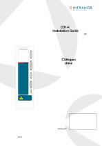
SERVO DRIVES & MOTION CONTROL CANopen drive
Open the catalog to page 1
! This is a general manual describing a series of servo speed amplifiers having output capability suitable for driving AC brushless sinusoidal servo motors. This manual may be used in conjunction with appropriate and referenced drawings pertaining to the various specific models. For the use of the drive (dimensions, wiring,...), see manual "CD1-k User Guide". For the CANopen communication, see manual "CD1-k – CANopen Communication Protocol". Maintenance procedures should be attempted only by highly skilled technicians having good knowledge of electronics and servo systems with variable speed...
Open the catalog to page 2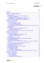
SERVO DRIVES & MOTION CONTROL 1.4 - COMMON SPECIFICATIONS TO THE THREE DRIVE TYPES CD1-k-230/I, CD1-k-400/I 5.1 - SPECIFICATION OF THE LOGIC INPUTS: INHIBIT, FC+, FC-, INDEX, CAPTURE, LOW
Open the catalog to page 3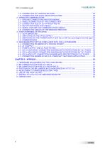
3.3 - SWITCHING ON THE POWER SUPPLY (230 Vac or 400 Vac according to the drive type) 30 4.4 - CD1-k-230/I DRIVE: CONNECTION DIAGRAM WITH PROTECTIONS BY "UL" FUSES... 32 4.5 - CD1-k-400/I DRIVE: CONNECTION DIAGRAM WITH PROTECTIONS BY "UL" FUSES... 33
Open the catalog to page 4
OINFRANOR SERVO DRIVES & MOTION CONTROL Series CD1-k drives with CANopen interface are PWM servo drives for the control of AC sinusoidal motors (brushless) with transmitter resolver. ■ a stand-alone single-axis block available in both mains operated versions 230 VAC and 400/480 VAC, Series CD1-k drives have their own supply. An auxiliary supply 24VDC +/- 15 % is required for the supply of the DC/DC converter. A 24 VDC battery supply with specific wiring allows to keep the position even after switching off the 24 VDC auxiliary supply. This wiring can be used for "absolute" operation with the CD1-k...
Open the catalog to page 5
CD1-k- Installation guide 2.3 - REFERENCE TO THE STANDARDS: "UL" LISTING CD1-k series have been « cULus » listed according to UL508C and UL840 regarding the insulator. This product was evaluated to: - the Third Edition of UL508C, the UL Standard for Power Conversion Equipment, dated May 2002 for the UL Listing (USL), - the CSA Standard for Industrial Control Equipment, C22.2 N° 14-95, dated August 1995 for the Canadian UL Listing (CNL). Providing that the manual is specifying that the end user has to provide an isolated power supply, for 24 VDC auxiliary input protected by a 4 A UL Listed fuse,...
Open the catalog to page 6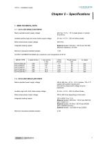
OINFRANOR SERVO DRIVES & MOTION CONTROL 1.1 - CD1-k-230/I SINGLE-AXIS DRIVE Mains operated power supply voltage Isolated auxiliary logic and motor brake supply voltage Motor phase-phase output voltage Integrated braking system Minimum inductance between phases OUTPUT CURRENT RATINGS (at a maximum room t 24 Vdc +/-15 % - 320 mA without brake 200 Vrms External resistor 100 Ohm / 100 W (dp 100/100) Minimum resistance: 50 Ohm 1.2 - CD1-K-400/I SINGLE-AXIS DRIVE Mains operated power supply voltage Auxiliary logic and motor brake supply voltage Motor phase-phase output voltage Integrated braking system...
Open the catalog to page 7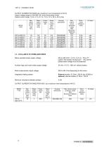
OUTPUT CURRENT RATINGS (at a maximum room temperature of 40°C) Output voltage range for 400-480 VAC (rms) three-phase mains Output current range: 1.8 A, 2.7 A, 5.1 A, 7.2 A, 14 A, 30 A, 45 A (rms) Mains operated power supply voltage Auxiliary logic and motor brake supply voltage Motor phase-phase output voltage Integrated braking system Minimum inductance between phases OUTPUT CURRENT RATINGS PER AXIS (at a 400 to 480 VAC + 10 %/- 15 % 3~, TN or TT system with earthed neutral point 50 to 60 Hz (phase-earth voltage must be balanced) 380 to 460 Vrms depending on the mains External resistor: 33...
Open the catalog to page 8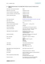
1.4 - COMMON SPECIFICATIONS TO THE THREE DRIVE TYPES CD1-k-230/I, CD1-k-400/I and CD1-k-400/14 P3 Servo loops: current, speed and position Mains filter on power supply Common mode filter on auxiliary supply Common mode filter on motor brake supply Position measurement sensor Power stage protections Motor brake control PWM switching frequency Minimum inductance between phases Digital current regulator (PI) Current loop bandwidth Internal current limitation Digital speed and position regulators Speed loop bandwidth Integrated in the drive Integrated in the drive Integrated in the drive Transmitter...
Open the catalog to page 9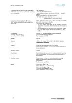
Compliance with the standards: CE certification. EMC standards: 360° shield connection, equipotentiality according - immunity: EN 61000.4-2-3-4-5 to the wiring rules. - conducted and radiated disturbances: EN 55011, Group 1, Electrical standards for industrial machines: leakage current > 30 mA (EMI filters). Conformity with the standards: UL listing CD1-k series have been “cULus” listed according to UL508C "360°" shield; equipotentiality according to the and UL840 regarding the insulator. wiring rules. This product was evaluated to: - the Third Edition of UL508C, the UL Standard for Power Conversion...
Open the catalog to page 10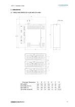
Drive type / Dimensions
Open the catalog to page 11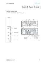
OINFRANOR SERVO DRIVES & MOTION CONTROL 1 - CONNECTORS LOCATION 1.1 - SINGLE-AXIS DRIVES CD1-k-230-I AND CD1-k-400-I XI oor©innc©3c b UJUUc=D c NODE ID BAUD
Open the catalog to page 15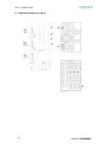
SERVO DRIVES & MOTION CONTROL
Open the catalog to page 16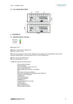
CD1-k – Installation Guide 1.3 – CD1-k-400/30 AND 45 DRIVE Ground 2 - LED DISPLAY 2.1 - IDENTIFICATION OF THE LEDs BUS (green) OK (green) SYS (red) SYS: System error SYS LED is continuously lit if System error, SYS LED is unlit if no error. OK: Errors are regrouped on the ‘OK’ LED: These errors are coded and can be displayed by means of the parameter setting software, via the serial link RS-232 or via the CANopen bus. OK LED: continuously blinking if error, OK LED: continuously lit if no error. The OK LED regroups the following errors: Power supply overvoltage No power voltage Out of 24 Vdc supply...
Open the catalog to page 17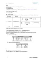
Any of these errors (except for the "Undervolt." error) involves: - the motor brake control, - opening of the AOK relay contact. This relay must be wired as described in Chapter 5, section 3, in order to switch-off the power supply and keep zero type standstill. The error "No power voltage" involves: - the motor brake control. The CANopen RUN LED indicates the status of the NMT state machine (see DS-301 - 9.52 NMT state machine): SINGLE FLASH See "DR-303-3 Indicator specification" for more information. 3 - DRIVE ADDRESSING: SELECTION OF THE TRANSMISSION SPEED Each drive of the network must be...
Open the catalog to page 18All Infranor Group catalogs and technical brochures
 XtrapulsPac_EN
4 Pages
 XtrapulsGemTemplates_e_1.4
21 Pages
 XtrapulsGem_User_Manual_v1.2.0.64
199 Pages
 XtrapulsGem_Inst_e_2.1
42 Pages
 XtrapulsGem_Inst_e_2.0
42 Pages
 SMTBSi-2Tz_en_2.1
43 Pages
 smt-100
32 Pages
 PacSimBox_d_1
1 Page
 Pac-SF01_flyer_en_18.02
4 Pages
 Pac_User_1.2.1.218
253 Pages
 Pac_Templates_en_1.9
27 Pages
 Pac_STO_Installation_en_2.2
13 Pages
 Pac_SF01_operating_en_1.6
63 Pages
 Pac_SF01_EN
4 Pages
 Pac_Installation_en_2.23
82 Pages
 Pac_flyer_en_17.12
4 Pages
 Option_CT_EMF
6 Pages
 MOVINOR_LH055_LH086_LH097_LH142
23 Pages
 ma_series
6 Pages
 GemSafeTorqueOff_en_1.1
12 Pages
 GemProgramming_e_1.1
47 Pages
 GDPS_old_version_1.1_1
11 Pages
 CD1pm_e_1.2(old)
18 Pages
 CD1pInst_e_7.2(old)
35 Pages
 CD1k_CANopenProtocol_e_1.3(old)
86 Pages
 CD1a_e_7.1(old)
45 Pages
 Catalogue gamme SMT-BD1
11 Pages
 BM20A(F)v3_0
20 Pages
 BM20A(D)v3_0
20 Pages
 BF400(GB)v2_2
21 Pages
 BF400(D)v2_2
21 Pages
 BF230(GB)v2_0
23 Pages
 BF230(F)v2_0
23 Pages
 BD2m_e_2.2
69 Pages
 BD2m(GB)2.0
70 Pages
 BD2_e_3.2
53 Pages
 BD2(GB)3.1
53 Pages
 BD2(D)3.1
54 Pages
 Movinor_LH_e
4 Pages
 ma_series
6 Pages
 BD1t(GB)3.1
81 Pages
 BD1t(F)3.0
85 Pages
 BD1pInst(GB)3.0
25 Pages
 BD1pInst(F)3.0
23 Pages
 BD1pInst(D)3.0
24 Pages
 BD1pCD1pUse_e_2.4
57 Pages
 BD1m(GB)5.0
58 Pages
 BD1m(F)5.0
57 Pages
 BD1m(D)v3_3
64 Pages
 BD1k(GB)2.1
35 Pages
 BD1k(F)2.1
36 Pages
 BD1j(GB)v2_41
19 Pages
 BD1j(F)v2_4
21 Pages
 BD1i(GB)v2_21
23 Pages
 BD1i(F)v2_2
27 Pages
 BD1h(F)3.0
65 Pages
 BD1h(D)3.0
59 Pages
 BD1g(GB)v3_0
28 Pages
 BD1g(F)v3_0
28 Pages
 BD1a400(GB)v2_3
43 Pages
 BD1a400(F)v2_3
44 Pages
 BD1a400(D)v2_3
45 Pages
 BD1(GB)7.1_noPW
45 Pages
 BD1(GB)7.1
45 Pages
 BD1(F)7.1_noPW
47 Pages
 BD1(F)7.1
47 Pages
 BD1(D)7.1
45 Pages
 BD1 Katalog
11 Pages
 08ma_ms_e_01700
20 Pages
 Easy_User_5.0.1.60.2
190 Pages
 08ma_mrm_em_01575
20 Pages
 01ma_smv_e_01953
40 Pages
 PacHP-SF_Flyer_en_23.06
4 Pages
 IRD_User_Manual_en_1.2.XX.54.rev_b
216 Pages
 PacHP_User_en_1.2.8.100.b
280 Pages
 PacHP_SF02_operating_en_1.6
103 Pages
 PacHP_SF01_operating_en_2.0
63 Pages
 PacHP_Installation_en_2.9
91 Pages
 PacHP_Series_Brochure
8 Pages
 PacHP_Flyer_us_20.10
4 Pages
 IRD_Installation_en_1.5
42 Pages
 GDPS_Installation_en_4.4
18 Pages
 Easy_STO_en_1.4
14 Pages
 Easy_DB_STO_en_1.2
14 Pages
 Easy_DB_Installation_en_1.4
36 Pages
 CD1pmUser_en_4.2
55 Pages
 CD1pmInst_en_8.15
40 Pages
 CD1k_CANopenProtocol_en_2.10.1.1
108 Pages
 CD1pm_ProfibusProtocol_en_1.5
50 Pages
 CD1kUser_en_2.3
26 Pages
 CD1a_en_8.17
62 Pages
 CD1kInst_en_5.16
46 Pages
 CD1_STO_en_1.8
16 Pages
 CD1_flyer_en_14.09
4 Pages
 Braking_Resistors_en_1.5
10 Pages
 XtracontrolDC2_EN
4 Pages
 Flyer_VisiTouchCNC_EN_V1.1-1
2 Pages
 XtraforsWashdown_EN-2024
2 Pages
 DataSheet_CybIO_CNC_V1.0
6 Pages
 XtraforsPrime_EN-2024
2 Pages
 XtraforsMSS_EN
4 Pages
 XtraforsMSA_EN_2024
2 Pages
 XtraforsEx_EN-2024
2 Pages
 XtraforsBR_EN-2024
2 Pages
 XtraforsBL_EN-2024
2 Pages
 XtraforsBC-ed01-vs3
4 Pages
 Manual_XtraforsPrime
46 Pages
 Drawing_1
1 Page
 Datasheet_MSS
5 Pages
 Datasheet_2
2 Pages
 Datasheet_1
4 Pages
 BLSBLT_series
2 Pages
 BL220221
2 Pages
 BL270
BL2702 Pages
 BL190
BL1902 Pages
 bl100_series
6 Pages
 bl40_series
6 Pages
 BL30
BL302 Pages
 2019-01_XtraforsFP-DSL_FR
4 Pages
 Movinor_T_EN
4 Pages
 Movinor_N_EN
4 Pages
 Movinor_Low_Voltage_EN
4 Pages
 Manual Movinor T 03-2026
46 Pages
 Manual Movinor N 03-2026
63 Pages
 XtrapulsEasy™ AC servo-drive
4 Pages
 XtrapulsCD1 AC servo-drives
4 Pages
 CybIO
CybIO6 Pages
 AC SERVOMOTORS
2 Pages
 Movinor® N AC Servomotors
4 Pages






Archived catalogs
 AN_CD1ak_AbsoluteEncoder_en_2.0
10 Pages
 AN_CD1ak_SinCosTracks_e_1.0
7 Pages
 AN_CD1pm_AbsoluteEncoder_en_2.0
10 Pages
 AN_CD1pm_SinCosTracks_e_1.0
7 Pages
 AN_DC_bus_interfacing_en_1.3
5 Pages
 CD1_EC_conformity_24.05
1 Page
 CD1_STO_conformity_19.02
2 Pages
 EtherCAT Interface_en_1.3
20 Pages
 Easy_EC_Conformity_24_10
1 Page
 GDPS_EC_conformity_24.07
1 Page
 IRD_EC_Conformity_25.03
1 Page
 PacHP_TÜV_certificate_25.07
2 Pages
 BD1c(F)v2_01
19 Pages
 BD1c(GB)v2_01
19 Pages
 BD1d(F)v2_01
25 Pages
 BD1d(GB)v2_01
25 Pages
 BD1e(F)v2_01
22 Pages
 BD1f(F)v2_01
17 Pages
 BD1f(GB)v2_01
18 Pages
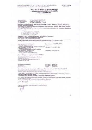 CE_conformity_Gem
1 Page
 Pac_EC_conformity_25.04
1 Page
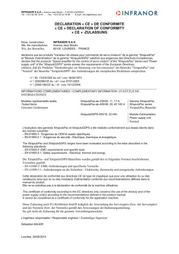 Pac_GDPS_CEconformity
1 Page
![SMT100D_e_1.01[1]](https://img.directindustry.com/pdf/repository_di/4620720/smt100d-e-101-1-1141223_1mg.jpg) SMT100D_e_1.01[1]
SMT100D_e_1.01[1]40 Pages
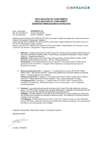 STO_declaration_Gem
2 Pages