
- Catalogs
- Infranor Group
- CD1k_CANopenProtocol_en_2.10.1.1


CD1k_CANopenProtocol_en_2.10.1.1

CD1k_CANopenProtocol_en_2.10.1.1
Receive PDO Communication Parameters:
1. 1st Receive PDO (RPDO1): COB-ID: Default 200h + Node-ID, Transmission Type: Default 253
2. 2nd Receive PDO (RPDO2): COB-ID: Default 300h + Node-ID, Transmission Type: Default 253
3. 3rd Receive PDO (RPDO3): COB-ID: Default 400h + Node-ID, Transmission Type: Default 1
Receive PDO Mapping:
1. 1st Receive PDO Mapping: Mapped Object: Control Word (60400010h)
2. 2nd Receive PDO Mapping: Mapped Object: Target Velocity (60FF0020h)
3. 3rd Receive PDO Mapping: Mapped Object: Interpolated Data Record (60C10120h)
Transmit PDO Communication Parameters:
1. 1st Transmit PDO (TPDO1): COB-ID: Default 180h + Node-ID, Transmission Type: Default 253
2. 2nd Transmit PDO (TPDO2): COB-ID: Default 280h + Node-ID, Transmission Type: Default 253
3. 3rd Transmit PDO (TPDO3): COB-ID: Default 380h + Node-ID, Transmission Type: Default 1
Transmit PDO Mapping:
1. 1st Transmit PDO Mapping: Mapped Object: Status Word (60410010h)
2. 2nd Transmit PDO Mapping: Mapped Object: Velocity Value (606C0020h)
3. 3rd Transmit PDO Mapping: Mapped Object: Actual Position Value (60640020h)
Device Profile Overview:
PDO Mapping:
1. Receive PDO: Control Word, Target Velocity, Interpolation Data Record, RPDO1 and RPDO2 are acyclic; RPDO3 is cyclic and synchronous.
2. Transmit PDO: Status Word, Velocity Value, Actual Position, TPDO1 and TPDO2 are remotely requested; TPDO3 is cyclic and synchronous.
Common Entries in the Object Dictionary:
1. Motor Type (6402h): PM Synchronous motor
2. Motor Data (6410h): Includes parameters like Motor Id, Number of Motor Pole Pairs, Phase Order, etc.
3. Supported Drive Modes (6502h): Includes Profile Position Mode, Profile Velocity Mode, etc.
4. Drive Manufacturer (6504h): 'Infranor'
5. Drive Data (6510h): Includes Drive Family Code, Drive Voltage, etc.
6. Digital Inputs (60FDh): Includes Negative Limit Switch, Positive Limit Switch, etc.
7. Digital Outputs (60FEh): Includes Physical Outputs and Bitmask.
Device Control: Drive State Machine: Describes the status and control sequence of the drive. Control Word (6040h): Includes functions like Switch On, Disable Voltage, Quick Stop, etc.
- End Velocity (Object 6081h): Defines the end velocity with a default value of 0 and unit in increments per second (inc/s).
- Profile Acceleration (Object 6083h): Specifies the acceleration profile with a default value of 10000h, measured in increments per second squared (inc/s²).
- Profile Deceleration (Object 6084h): Similar to acceleration, with the same default value and unit.
- Motion Profile Type (Object 6086h): Determines the type of motion profile, either trapezoidal (0) or S-curve (-1), with a default value of 0.
- Defines minimum and maximum position limits for a linear axis, with a range from -231 to 231-1.
- Position Window (Object 6067h): Sets a range of accepted positions around the target position, defaulting to 0.
- Position Modulo (Object 307Fh): Resets the position counter at a specified modulo value, defaulting to 0.
- Homing Offset (Object 607Ch): Defines the position feedback value at the homing position.
- Homing Method (Object 6098h): Lists various methods for finding the homing position, with specific methods for different scenarios.
- Homing Speeds (Object 6099h): Specifies speeds during the homing process.
- Homing Acceleration (Object 609Ah): Sets the acceleration during homing, defaulting to 00010000h.
- Position Actual Value (Objects 6063h and 6064h): Provides the current position value in increments.
- Position Loop Deadband (Object 3067h): Introduces a deadband around the position loop setpoint to manage specific applications.
- Following Error Window (Object 6065h): Defines the acceptable error range before triggering a fault.
- Includes parameters like Proportional Position Gain, Feedforward Speed Gain, and others to fine-tune position control.
The document discusses feedforward terms used to reduce following errors during motor acceleration and deceleration phases. It specifies the data type as Unsigned16 with a value range of 0 to FFFFh and a default value stored in EEPROM. The feedforward speed gain is a combination of damping speed gain and feedforward friction gain, which helps cancel the load viscous friction effect.
Interpolated Position Mode
This mode is used for coordinated control of multiple axes, requiring trajectory generation by the host controller. The document details the synchronization of cycle times using SYNC messages and describes different interpolation modes: linear, PV cubic, and P3 cubic. Each mode has specific requirements for position and velocity data, with linear interpolation being optimal at very low speeds.
Object Dictionary Entries
The document provides detailed descriptions of various objects related to interpolation and velocity control, including their indices, data types, access permissions, and default values. Key objects include Interpolation Submode Select, Interpolation Data Record, and Interpolation Data Configuration.
Profile Velocity Mode
This mode allows operation with a velocity reference, closing only the speed and current loops. The document lists object dictionary entries for velocity control, including actual and demand values, velocity window and threshold settings, and target velocity. It also describes the ramp function and velocity control parameter set, detailing proportional, integral, and derivative gains.
Profile Torque Mode
In torque mode, the drive operates with current loops without speed or position control. The document outlines object dictionary entries for torque control, including target torque, torque slope, and torque control parameter set. It also describes the filtered current monitor and current monitor filter.
Index 3078h defines the current monitor filter with a range of 500 to 10,000 micro-seconds and a default value of 4000. It is accessible for read and write operations.
This mode is applicable for motors with a resolver for position feedback. It requires configuration of Pulse and Direction inputs. The mode is activated by setting object 6060 to -1. Key control and status bits include enabling pulse following and indicating pulse following status. Parameters such as motor speed and direction are controlled by input pulses and the Direction input logic state.
This mode synchronizes the servo motor with a master axis using a gearing ratio. It is activated by setting object 6060 to -2. Control and status bits manage motor gearing and offset profiles. Parameters include revolution increments and gearing ratio calculations based on sensor type.
Includes object dictionary entries for error and stop functions, current functions, inputs/outputs, position control, and more. Key objects include Drive Error Code (3020h), Warning Code (3021h), and Fault Reaction Masks (3330h, 3331h) which define error-triggered stops.
Defines various objects for managing errors and stops, such as Drive Error Code, Warning Code, and Fault Reaction Masks. These objects specify conditions under which the motor will stop or slow down, including position limits, temperature warnings, and current limits.
This section describes the monitoring of motor temperature using a sensor. The threshold for warnings is calculated based on the equivalent resistance of the temperature value. The formula provided helps in determining the resistance, which is crucial for understanding the temperature sensor's specifications.
- Current Offset (30D0h): Defines an offset for current output, useful for vertical axes. It is adjustable within a specified range and expressed as a percentage of amplifier rating.
- Current Limitation (30D1h): Sets a dynamic limit on current output, adjustable up to the amplifier's maximum current.
- Current Monitor (30D4h): Monitors motor current, relying on correct motor position for accuracy.
- I²t Monitor (30D5h): Calculates the motor RMS current value over the last 4 seconds, providing a percentage of the amplifier rating.
- Voltage Monitor (30E0h): Monitors motor voltage with specific data conversion values for different amplifiers.
- Digital Inputs Bitmask (30FDh): Describes the default functions of digital inputs, which can be repurposed as simple digital inputs.
- Analog Inputs: Includes voltage and low-pass filter settings for analog inputs, with specific conversion and compensation procedures.
This section details the calculation of motor position, including the use of internal raw position and position offsets. It explains how to handle motor shifts when the drive is out of logic supply and provides methods for calculating and adjusting position offsets.
Defines the timing for enabling or disabling the drive via control words, including delays for servo loop output and motor brake reactions.
Describes the ability to capture motor and secondary sensor positions at a high rate using specific logic inputs, with configurations based on sensor feedback.
Object Code: VAR
Data Type: Unsigned16
Access: Read/Write
Default Value: EEPROM
Bit 8 controls Cogging Torque Compensation, where 0 disables and 1 enables it.
Cogging Torque Acquisition Procedure
Index: 3492h
Data Type: Unsigned32
Access: Write Only
To execute, write the signature 'coga' to this object.
Digital Cam Configuration
Index: 2500h
Cam Configuration Register with 4 sub-indexes:
- Cam Enable Register: Enables corresponding cam.
- Cam Polarity Register: Sets cam output polarity.
- Cam Type Register: Defines cam type (0 for 1 position, 1 for 2 positions).
- Cam Hysteresis Register: Defines cam position hysteresis.
Index: 2501h
Defines positions for each cam, with 20 elements for 10 cams.
Cam Status
Index: 2502h
Data Type: Unsigned16
Access: Read Only
Outputs the status of each cam.
Absolute Encoder Feedback
Index: 3216h
Defines encoder increments per revolution and revolutions for multi-turn encoders.
Index: 3215h
Absolute position reset procedure with signatures 'razp' and 'setp' for resetting and centering.
Index: 3219h
Defines encoder absolute position offset.
Index: 3218h
Defines maximum absolute position value.
SinCos Inputs Calibration
Index: 3496h
SinCos inputs error compensation procedure with signature 'scmp'.
Communication and Object Dictionary
Includes various communication parameters and object dictionary entries for device configuration and operation.
- Device Control: Includes control and status words, mode of operation, and quick stop option code.
- Position Sensor Group: Details on polarity, position resolution, encoder input selection, and motor feedback programming.
- Profile Position Mode: Covers target position, motor speed, profile velocity, acceleration, and deceleration parameters.
- Homing Mode: Describes home offset, homing method, speeds, and acceleration.
- Position Control Function: Includes position actual value, following error window, and position control parameter set.
- Interpolated Position Mode: Discusses interpolation submode, data record, and configuration.
- Profile Velocity Mode: Details velocity sensor values, demand, and control parameters.
- Profile Torque Mode: Covers target torque, torque slope, and control parameters.
- Manufacturer Specific: Includes cam configuration, drive error codes, and sensor feedback.
- Installation: Involves wiring, powering, and commissioning using VDSetup software. Important to disable CAN bus during setup and store parameters in EEPROM.
- Operation: Primarily runs in interpolated position mode. Steps include starting communication (NMT), setting communication parameters (SDO), starting synchronization (SYNC), and data exchange (PDO).
- Communication Parameters: Key parameters include communication cycle period and synchronous window length. Adjustments needed for interpolated position mode.
- Data Exchange: Involves position demand and current position values. Mapping of PDOs can be modified for other data exchanges.
- Servo Control: Controlled via control and status words, accessible through SDO or RPDO1/TPDO.
The document provides a state diagram in section 3.3.1, detailing the sequence to enable a drive (servo on). The sequence involves sending a control word from the controller and receiving a status word from the drive, transitioning through various states: 'Switch On Disabled', 'Ready To Switch On', and 'Operation Enable'.
Drive State Transition
- Switch On Disabled: Control word xx00h, Status word x240h, Drive is disabled.
- Ready To Switch On: Control word xx06h, Status word x221h, Drive is disabled.
- Operation Enable: Control word xx0Fh, Status word x227h, Drive is enabled.
The transition from 'Switch On Disabled' to 'Operation Enable' must pass through 'Ready To Switch On'.
Error Handling
If an error occurs, the drive enters 'Fault Reaction Active' and then 'Fault' state. To exit 'Fault', a rising edge of bit 7 in the control word is required. After resetting the fault, the drive returns to 'Switch On Disabled'.
IP-Mode Activation
In 'Operation Enable', setting bit 4 of the control word activates IP-Mode, confirmed by bit 12 in the status word. The drive then follows the position demand value via RPDO3. A mismatch between position demand and current position when bit 4 is set will cause a following error.
Additional Considerations
Errors trigger an emergency message to the controller. The 'Fault' state is indicated by status word xxxFh, with error details in object 3020h.
Catalog excerpts
CINFRANOR CANopen Communication Profile CANopen Drive
Open the catalog to page 1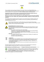
CD1-k CANopen Communication Profile WARNING ! This is a general manual describing the CANopen Communication Profile of the INFRANOR CD1-k drive (hardware release version 2.0 and firmware release from version 11.E3). For the installation and commissioning of the drive, please refer to the appropriate manuals (CD1-k Installation Guide and CD1k User Guide). Instructions for storage, use after storage, commissioning as well as all technical details require the MANDATORY reading of the manual before getting the amplifiers operational. Maintenance procedures should be attempted only by highly skilled...
Open the catalog to page 2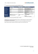
CD1-k – CANopen Communication Profile Information and sorting instructions regarding INFRANOR Waste category Recyclable waste Recyclable waste Recyclable waste Recyclable waste Electronical boards and components WEEE (Waste Electronic and Electrical Equipment) Dangerous industrial waste Waste management Waste disposal centre / collection point of recyclable waste Waste disposal centre / collection point of recyclable waste Waste disposal centre / metal collection point Waste disposal centre / metal collection point France: http://www.ecosystem.eco/fr/sousrubrique/solutions Abroad: Country-specific...
Open the catalog to page 3
CD1-k - CANopen Communication Profile
Open the catalog to page 4
CD1-k - CANopen Communication Profile
Open the catalog to page 5
CD1-k - CANopen Communication Profile
Open the catalog to page 6
CD1-k - CANopen Communication Profile
Open the catalog to page 7
CD1-k – CANopen Communication Profile
Open the catalog to page 8
CD1-k – CANopen Communication Profile Chapter 1 – Overview 3.13 - REFERENCE CiA DS-201..207 CAN Application Layer for Industrial Applications Version 1.1 Application Layer and Communication Profile Version 4.01 Device Profile: Drive and Motion Control Version 1.1 Controller Area Network CAN in Automation e. V. CAN-Bus international manufacturer and user organisation. CAN Application Layer. The Application layer for CAN as specified by CiA. Communication Object is a CAN message. Data must be sent accross a CAN network inside a COB. COB-Identifier. Each CAN message has a single identifier. There...
Open the catalog to page 9
CD1-k - CANopen Communication Profile Device Control: The drive starting and stopping are executed by the state machine. The state machine - handled with a control word and a status word via CAN bus - gives the possibility to control the state of the drive: servo on/off, start/stop movement, fault reset... Operation modes: The operation mode defines the behaviour of the drive : Homing Mode: In this mode, various methods can be used to find a home position. Profile Position Mode: In this mode, a trapezoidal trajectory generator gives the drive the possibility to execute a positioning with pre-set...
Open the catalog to page 10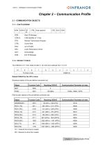
CD1-k - CANopen Communication Profile OINFRANORChapter 2 - Communication Profile2.1 - COMMUNICATION OBJECTS2.1.1 - CAN TELEGRAM SOM SOM : COB-ID RTR : CTRL: Data : CRC : ACK : EOM : Start Of Message COB-Identifier of 11 bits Remote Transmission Request Control field up to 8 bytes Cyclic Redundancy Check 2.1.2 - DEFAULT COB-ID The COB-ID is of 11 bits. Node-ID (bits 0 - 6) is the drive address from 1 to 127. TX = T ransmit from drive to master RX = Receive by drive from master Chapter 2 - Communication Profile
Open the catalog to page 11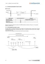
CD1-k - CANopen Communication Profile OINFRANOR2.1.3 - NETWORK MANAGEMENT OBJECTS (NMT)NMT Protocols NMT Master Node-ID: The Node-ID indicates the address of the CD1-k (defined by switches). If Node_ID = 0, the protocol addresses all NMT slaves. The SYNC object is a broadcast message sent by the master. This message provides a network clock. The period is specified by the communication cycle period (object 1006h). The Infranor servo-drives use this SYNC message to synchronize their clock. At least 180 ms are necessary for the servo-drive to start the synchronisation. Communication cycle Synchronous...
Open the catalog to page 12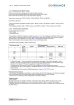
CD1-k - CANopen Communication Profile OINFRANOR2.1.5 - PROCESS DATA OBJECT (PDO) PDOs are unconfirmed messages used for real-time data exchange. PDOs sent by the master are RPDOs and PDOs sent by the drive are TPDOs. Data in each PDO are defined by a list of objects (PDO mapping). - PDO communication parameters at object 1400h + RPDO_number-1 (for RPDO) or 1800h + TPDO_number-1 (for TPDO) - PDO mapping at object 1600h + RPDO_number-1 (for RPDO) or 1A00h + TPDO_number-1 (for TPDO) - Transmission type The distribution of COB-ID is defined by default (see section 2.1.2). The modification of COB-ID...
Open the catalog to page 13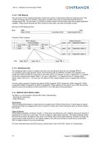
CD1-k – CANopen Communication Profile 2.1.5.2 - PDO Mapping The sub-index 0 of the mapping parameter contains the number of valid entries within the mapping record. This number of entries is also the number of application variables which shall be transmitted/received with the corresponding PDO. The sub-index 1 to number of entries contains the information about the mapped application variables. These entries describe the PDO contents by their index, sub-index and length (in bits). Structure of PDO Mapping Entry: Byte : PDO mapping 3 (nb of entries) yyyyh (index) yyh (sub-index) zzzzh zzh xxxxh...
Open the catalog to page 14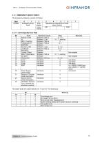
CD1-k - CANopen Communication Profile OINFRANOR 2.1.7 - EMERGENCY OBJECT (EMCY) The Emergency telegram consists of 8 bytes: Chapter 2 - Communication Profile
Open the catalog to page 15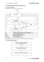
CD1-k – CANopen Communication Profile 2.2 - NETWORK INITIALISATION AND SYSTEM BOOT-UP 2.2.1 - NMT STATE MACHINE The NMT state machine defines the communication status. Power On (1) Pre-operational NMT, SDO, Sync, Emcy (7) (13) Operational NMT, SDO, Sync, Emcy, PDO At Power on, the initialisation state is automatically entered Once the Initialisation over, Pre-Operational is automatically entered Start_Remote_Node indication Enter_Pre-Operational_State indication Stop_Remote_Node indication Reset_Node indication Reset_Communication indication Minimum Boot-Up consists of one CAN telegram : a broadcast...
Open the catalog to page 16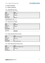
CD1-k - CANopen Communication Profile OINFRANOR2.3 - OBJECT DICTIONARY2.3.1 - GENERAL INFORMATION2.3.1.1 - Object 1000h: Device Type This object describes the type of a device. Chapter 2 - Communication Profile
Open the catalog to page 17All Infranor Group catalogs and technical brochures
 XtrapulsPac_EN
4 Pages
 SMTBSi-2Tz_en_2.1
43 Pages
 PacSimBox_d_1
1 Page
 Pac-SF01_flyer_en_18.02
4 Pages
 Pac_User_1.2.1.218
253 Pages
 Pac_Templates_en_1.9
27 Pages
 Pac_STO_Installation_en_2.2
13 Pages
 Pac_SF01_operating_en_1.6
63 Pages
 Pac_SF01_EN
4 Pages
 Pac_Installation_en_2.23
82 Pages
 Pac_flyer_en_17.12
4 Pages
 Option_CT_EMF
6 Pages
 MOVINOR_LH055_LH086_LH097_LH142
23 Pages
 ma_series
6 Pages
 GemSafeTorqueOff_en_1.1
12 Pages
 CD1pm_e_1.2(old)
18 Pages
 CD1pInst_e_7.2(old)
35 Pages
 CD1kInst_e_4.1(old)
40 Pages
 CD1k_CANopenProtocol_e_1.3(old)
86 Pages
 CD1a_e_7.1(old)
45 Pages
 Catalogue gamme SMT-BD1
11 Pages
 BM20A(F)v3_0
20 Pages
 BM20A(D)v3_0
20 Pages
 BF400(GB)v2_2
21 Pages
 BF400(D)v2_2
21 Pages
 BF230(GB)v2_0
23 Pages
 BF230(F)v2_0
23 Pages
 BD2m_e_2.2
69 Pages
 BD2m(GB)2.0
70 Pages
 BD2_e_3.2
53 Pages
 BD2(GB)3.1
53 Pages
 BD2(D)3.1
54 Pages
 Movinor_LH_e
4 Pages
 ma_series
6 Pages
 BD1t(GB)3.1
81 Pages
 BD1t(F)3.0
85 Pages
 BD1pInst(GB)3.0
25 Pages
 BD1pInst(F)3.0
23 Pages
 BD1pInst(D)3.0
24 Pages
 BD1pCD1pUse_e_2.4
57 Pages
 BD1m(GB)5.0
58 Pages
 BD1m(F)5.0
57 Pages
 BD1m(D)v3_3
64 Pages
 BD1k(GB)2.1
35 Pages
 BD1k(F)2.1
36 Pages
 BD1j(GB)v2_41
19 Pages
 BD1j(F)v2_4
21 Pages
 BD1i(GB)v2_21
23 Pages
 BD1i(F)v2_2
27 Pages
 BD1h(F)3.0
65 Pages
 BD1h(D)3.0
59 Pages
 BD1g(GB)v3_0
28 Pages
 BD1g(F)v3_0
28 Pages
 BD1a400(GB)v2_3
43 Pages
 BD1a400(F)v2_3
44 Pages
 BD1a400(D)v2_3
45 Pages
 BD1(GB)7.1_noPW
45 Pages
 BD1(GB)7.1
45 Pages
 BD1(F)7.1_noPW
47 Pages
 BD1(F)7.1
47 Pages
 BD1(D)7.1
45 Pages
 BD1 Katalog
11 Pages
 Easy_User_5.0.1.60.2
190 Pages
 01ma_smv_e_01953
40 Pages
 PacHP-SF_Flyer_en_23.06
4 Pages
 IRD_User_Manual_en_1.2.XX.54.rev_b
216 Pages
 PacHP_User_en_1.2.8.100.b
280 Pages
 PacHP_SF02_operating_en_1.6
103 Pages
 PacHP_SF01_operating_en_2.0
63 Pages
 PacHP_Installation_en_2.9
91 Pages
 PacHP_Series_Brochure
8 Pages
 PacHP_Flyer_us_20.10
4 Pages
 IRD_Installation_en_1.5
42 Pages
 Easy_STO_en_1.4
14 Pages
 Easy_DB_STO_en_1.2
14 Pages
 Easy_DB_Installation_en_1.4
36 Pages
 CD1pmUser_en_4.2
55 Pages
 CD1pmInst_en_8.15
40 Pages
 CD1pm_ProfibusProtocol_en_1.5
50 Pages
 CD1kUser_en_2.3
26 Pages
 CD1a_en_8.17
62 Pages
 CD1kInst_en_5.16
46 Pages
 CD1_STO_en_1.8
16 Pages
 CD1_flyer_en_14.09
4 Pages
 Braking_Resistors_en_1.5
10 Pages
 XtracontrolDC2_EN
4 Pages
 Flyer_VisiTouchCNC_EN_V1.1-1
2 Pages
 XtraforsWashdown_EN-2024
2 Pages
 DataSheet_CybIO_CNC_V1.0
6 Pages
 XtraforsPrime_EN-2024
2 Pages
 XtraforsMSS_EN
4 Pages
 XtraforsMSA_EN_2024
2 Pages
 XtraforsEx_EN-2024
2 Pages
 XtraforsBR_EN-2024
2 Pages
 XtraforsBL_EN-2024
2 Pages
 XtraforsBC-ed01-vs3
4 Pages
 Manual_XtraforsPrime
46 Pages
 Drawing_1
1 Page
 Datasheet_MSS
5 Pages
 Datasheet_2
2 Pages
 Datasheet_1
4 Pages
 BLSBLT_series
2 Pages
 BL220221
2 Pages
 BL270
BL2702 Pages
 BL190
BL1902 Pages
 bl100_series
6 Pages
 bl40_series
6 Pages
 BL30
BL302 Pages
 2019-01_XtraforsFP-DSL_FR
4 Pages
 Movinor_T_EN
4 Pages
 Movinor_N_EN
4 Pages
 Movinor_Low_Voltage_EN
4 Pages
 Manual Movinor T 03-2026
46 Pages
 Manual Movinor N 03-2026
63 Pages
 XtrapulsEasy™ AC servo-drive
4 Pages
 XtrapulsCD1 AC servo-drives
4 Pages
 CybIO
CybIO6 Pages
 AC SERVOMOTORS
2 Pages
 Movinor® N AC Servomotors
4 Pages






Archived catalogs
 AN_CD1ak_AbsoluteEncoder_en_2.0
10 Pages
 AN_CD1ak_SinCosTracks_e_1.0
7 Pages
 AN_CD1pm_AbsoluteEncoder_en_2.0
10 Pages
 AN_CD1pm_SinCosTracks_e_1.0
7 Pages
 AN_DC_bus_interfacing_en_1.3
5 Pages
 CD1_EC_conformity_24.05
1 Page
 CD1_STO_conformity_19.02
2 Pages
 EtherCAT Interface_en_1.3
20 Pages
 Easy_EC_Conformity_24_10
1 Page
 GDPS_EC_conformity_24.07
1 Page
 IRD_EC_Conformity_25.03
1 Page
 PacHP_TÜV_certificate_25.07
2 Pages
 BD1c(F)v2_01
19 Pages
 BD1c(GB)v2_01
19 Pages
 BD1d(F)v2_01
25 Pages
 BD1d(GB)v2_01
25 Pages
 BD1e(F)v2_01
22 Pages
 BD1f(F)v2_01
17 Pages
 BD1f(GB)v2_01
18 Pages
 Pac_EC_conformity_25.04
1 Page




















