
- Catalogs
- Infranor Group
- CD1k_CANopenProtocol_e_1.3(old)


CD1k_CANopenProtocol_e_1.3(old)

CD1k_CANopenProtocol_e_1.3(old)
Catalog excerpts
CANopen Communication Profile SERVO DRIVES & MOTION CONTROL
Open the catalog to page 1
CD1-k, BD1/k, BD2/k CANopen Communication Profile
Open the catalog to page 2
CD1-k, BD1/k, BD2/k – CANopen Communication Profile ! This is a general manual describing the CANopen Communication Profile of the INFRANOR CD1-k, BD1/k and BD2/k drive. For the installation and commissioning of the drive, please refer to the appropriate manuals. Maintenance procedures should be attempted only by highly skilled technicians having good knowledge of electronics and servo systems with variable speed (EN 60204-1 standard) and using proper test equipment. The conformity with the standards and the "CE" approval is only valid if the items are installed according to the recommendations...
Open the catalog to page 3
CD1-k, BD1/k, BD2/k – CANopen Communication Profile
Open the catalog to page 4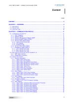
CD1-k, BD1/k, BD2/k - CANopen Communication Profile Content PAGE
Open the catalog to page 5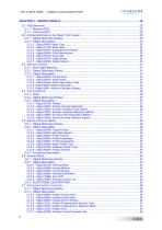
CD1-k, BD1/k, BD2/k - CANopen Communication Profile SERVO DRIVES & MOTION CONTROL
Open the catalog to page 6
CD1-k, BD1/k, BD2/k - CANopen Communication Profile
Open the catalog to page 7
CD1-k, BD1/k, BD2/k – CANopen Communication Profile
Open the catalog to page 8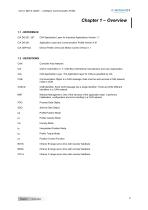
CD1-k, BD1/k, BD2/k – CANopen Communication Profile Chapter 1 – Overview 1.1 - REFERENCE CiA DS-201..207 CAN Application Layer for Industrial Applications Version 1.1 Application Layer and Communication Profile Version 4.01 Device Profile: Drive and Motion Control Version 1.1 Controller Area Network CAN in Automation e. V. CAN-Bus international manufacturer and user organisation. CAN Application Layer. The Application layer for CAN as specified by CiA. Communication Object is a CAN message. Data must be sent accross a CAN network inside a COB. COB-Identifier. Each CAN message has a single identifier....
Open the catalog to page 9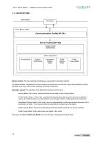
CD1-k, BD1/k, BD2/k - CANopen Communication Profile Device Control: The drive starting and stopping are executed by the state machine. The state machine - handled with a control word and a status word via CAN bus - gives the possibility to control the state of the drive: servo on/off, start/stop movement, fault reset... Operation modes: The operation mode defines the behaviour of the drive : Homing Mode: In this mode, various methods can be used to find a home position. Profile Position Mode: In this mode, a trapezoidal trajectory generator gives the drive the possibility to execute a positioning...
Open the catalog to page 10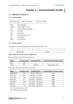
CD1-k, BD1/k, BD2/k - CANopen Communication Profile OINFRANOR SERVO DRIVES & MOTION CONTROL COB-ID : COB-Identifier of 11 bits RTR : Remote Transmission Request CTRL: Control field CRC : Cyclic Redundancy Check 2.1.2 - DEFAULT COB-ID The COB-ID is of 11 bits. Node-ID (bits 0 - 6) is the drive address from 1 to 127. TX = Transmit from drive to master RX = Receive by drive from master Chapter 2 - Communication Profile
Open the catalog to page 11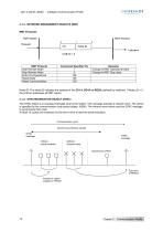
CD1-k, BD1/k, BD2/k - CANopen Communication Profile Node-ID: The Node-ID indicates the address of the CD1-k, BD1/k or BD2/k (defined by switches). If Node_ID = 0, the protocol addresses all NMT slaves. 2.1.4 - SYNCHRONISATION OBJECT (SYNC) The SYNC object is a broadcast message sent by the master. This message provides a network clock. The period is specified by the communication cycle period (object 1006h). The Infranor servo-drives use this SYNC message to synchronize their clock. At least 10 cycles are necessary for the servo-drive to start the synchronisation. Communication cycle Synchronous...
Open the catalog to page 12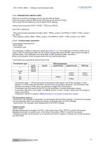
CD1-k, BD1/k, BD2/k - CANopen Communication Profile PDOs are unconfirmed messages used for real-time data exchange. PDOs sent by the master are RPDOs and PDOs sent by the drive are TPDOs. Data in each PDO are defined by a list of objects (PDO mapping). Infranor servo drives have TPDO1, RPDO1, TPDO3 and RPDO3. - PDO communication parameters at object 1400h + RPDO_number-1 (for RPDO) or 1800h + TPDO_number-1 (for TPDO) - PDO mapping at object 1600h + RPDO_number-1 (for RPDO) or 1A00h + TPDO_number-1 (for TPDO) - Transmission type The distribution of COB-ID is defined by default (see section 2.1.2)....
Open the catalog to page 13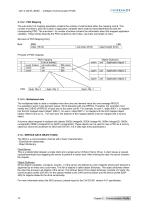
CD1-k, BD1/k, BD2/k - CANopen Communication Profile The sub-index 0 of mapping parameter contains the number of valid entries within the mapping record. This number of entries is also the number of application variables which shall be transmitted/received with the corresponding PDO. The sub-index 1 to number of entries contains the information about the mapped application variables. These entries describe the PDO contents by their index, sub-index and length (in bits). Structure of PDO Mapping Entry: Byte : MSB___LSB index (16 bit) | sub-index (8 bit) | object length (8 bit) ~~| Object Dictionary...
Open the catalog to page 14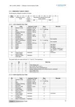
CD1-k, BD1/k, BD2/k - CANopen Communication Profile 2.1.7 - EMERGENCY OBJECT (EMCY) The Emergency telegram consists of 8 bytes: Chapter 2 - Communication Profile
Open the catalog to page 15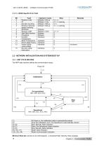
CD1-k, BD1/k, BD2/k – CANopen Communication Profile Fault Position Limits I2 t Encoder Counting Position Following / Speed Following EEPROM Synchro_CAN Hall Effect Sensors Procedure Amplifier Temperature Motor Temperature Power Stage Failure Power Supply Undervoltage Encoder Cable Interruption treatment / Cycle Software / 500 µs Software / 2 ms Software / 500 µs Software / 500 µs Software Software / cycle Software Software Hardware Hardware Hardware Hardware 2.2 - NETWORK INITIALISATION AND SYSTEM BOOT-UP 2.2.1 - NMT STATE MACHINE The NMT state machine defines the communication status. Power...
Open the catalog to page 16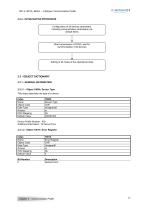
CD1-k, BD1/k, BD2/k - CANopen Communication Profile 2.3 - OBJECT DICTIONARY 2.3.1 - GENERAL INFORMATION This object describes the type of a device. Device Profile Number : 402 Additional Information : 02 Servo Drive Description Generic Error Chapter 2 - Communication Profile
Open the catalog to page 17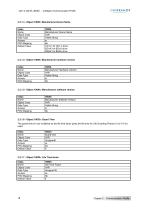
CD1-k, BD1/k, BD2/k - CANopen Communication Profile 2.3.1.3 - Object 1008h: Manufacturer Device Name Chapter 2 - Communication Profile
Open the catalog to page 18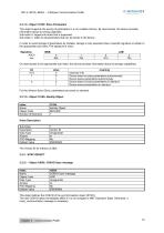
CD1-k, BD1/k, BD2/k - CANopen Communication Profile This object supports the saving of parameters in a non volatile memory. By read access, the device provides information about its saving capacities. Sub-index 0: largest sub-index that is supported. Sub-index 1: refers to all parameters that can be stored in the device. In order to avoid storage of parameters by mistake, storage is only executed when a specific signature is written to the appropriate sub-index. The signature is 'save'. This object defines the COB-ID of the synchronisation object (SYNC). The new COB-ID takes immediately effect...
Open the catalog to page 19All Infranor Group catalogs and technical brochures
 XtrapulsPac_EN
4 Pages
 SMTBSi-2Tz_en_2.1
43 Pages
 PacSimBox_d_1
1 Page
 Pac-SF01_flyer_en_18.02
4 Pages
 Pac_User_1.2.1.218
253 Pages
 Pac_Templates_en_1.9
27 Pages
 Pac_STO_Installation_en_2.2
13 Pages
 Pac_SF01_operating_en_1.6
63 Pages
 Pac_SF01_EN
4 Pages
 Pac_Installation_en_2.23
82 Pages
 Pac_flyer_en_17.12
4 Pages
 Option_CT_EMF
6 Pages
 MOVINOR_LH055_LH086_LH097_LH142
23 Pages
 ma_series
6 Pages
 GemSafeTorqueOff_en_1.1
12 Pages
 CD1pm_e_1.2(old)
18 Pages
 CD1pInst_e_7.2(old)
35 Pages
 CD1kInst_e_4.1(old)
40 Pages
 CD1a_e_7.1(old)
45 Pages
 Catalogue gamme SMT-BD1
11 Pages
 BM20A(F)v3_0
20 Pages
 BM20A(D)v3_0
20 Pages
 BF400(GB)v2_2
21 Pages
 BF400(D)v2_2
21 Pages
 BF230(GB)v2_0
23 Pages
 BF230(F)v2_0
23 Pages
 BD2m_e_2.2
69 Pages
 BD2m(GB)2.0
70 Pages
 BD2_e_3.2
53 Pages
 BD2(GB)3.1
53 Pages
 BD2(D)3.1
54 Pages
 Movinor_LH_e
4 Pages
 ma_series
6 Pages
 BD1t(GB)3.1
81 Pages
 BD1t(F)3.0
85 Pages
 BD1pInst(GB)3.0
25 Pages
 BD1pInst(F)3.0
23 Pages
 BD1pInst(D)3.0
24 Pages
 BD1pCD1pUse_e_2.4
57 Pages
 BD1m(GB)5.0
58 Pages
 BD1m(F)5.0
57 Pages
 BD1m(D)v3_3
64 Pages
 BD1k(GB)2.1
35 Pages
 BD1k(F)2.1
36 Pages
 BD1j(GB)v2_41
19 Pages
 BD1j(F)v2_4
21 Pages
 BD1i(GB)v2_21
23 Pages
 BD1i(F)v2_2
27 Pages
 BD1h(F)3.0
65 Pages
 BD1h(D)3.0
59 Pages
 BD1g(GB)v3_0
28 Pages
 BD1g(F)v3_0
28 Pages
 BD1a400(GB)v2_3
43 Pages
 BD1a400(F)v2_3
44 Pages
 BD1a400(D)v2_3
45 Pages
 BD1(GB)7.1_noPW
45 Pages
 BD1(GB)7.1
45 Pages
 BD1(F)7.1_noPW
47 Pages
 BD1(F)7.1
47 Pages
 BD1(D)7.1
45 Pages
 BD1 Katalog
11 Pages
 Easy_User_5.0.1.60.2
190 Pages
 01ma_smv_e_01953
40 Pages
 PacHP-SF_Flyer_en_23.06
4 Pages
 IRD_User_Manual_en_1.2.XX.54.rev_b
216 Pages
 PacHP_User_en_1.2.8.100.b
280 Pages
 PacHP_SF02_operating_en_1.6
103 Pages
 PacHP_SF01_operating_en_2.0
63 Pages
 PacHP_Installation_en_2.9
91 Pages
 PacHP_Series_Brochure
8 Pages
 PacHP_Flyer_us_20.10
4 Pages
 IRD_Installation_en_1.5
42 Pages
 Easy_STO_en_1.4
14 Pages
 Easy_DB_STO_en_1.2
14 Pages
 Easy_DB_Installation_en_1.4
36 Pages
 CD1pmUser_en_4.2
55 Pages
 CD1pmInst_en_8.15
40 Pages
 CD1k_CANopenProtocol_en_2.10.1.1
108 Pages
 CD1pm_ProfibusProtocol_en_1.5
50 Pages
 CD1kUser_en_2.3
26 Pages
 CD1a_en_8.17
62 Pages
 CD1kInst_en_5.16
46 Pages
 CD1_STO_en_1.8
16 Pages
 CD1_flyer_en_14.09
4 Pages
 Braking_Resistors_en_1.5
10 Pages
 XtracontrolDC2_EN
4 Pages
 Flyer_VisiTouchCNC_EN_V1.1-1
2 Pages
 XtraforsWashdown_EN-2024
2 Pages
 DataSheet_CybIO_CNC_V1.0
6 Pages
 XtraforsPrime_EN-2024
2 Pages
 XtraforsMSS_EN
4 Pages
 XtraforsMSA_EN_2024
2 Pages
 XtraforsEx_EN-2024
2 Pages
 XtraforsBR_EN-2024
2 Pages
 XtraforsBL_EN-2024
2 Pages
 XtraforsBC-ed01-vs3
4 Pages
 Manual_XtraforsPrime
46 Pages
 Drawing_1
1 Page
 Datasheet_MSS
5 Pages
 Datasheet_2
2 Pages
 Datasheet_1
4 Pages
 BLSBLT_series
2 Pages
 BL220221
2 Pages
 BL270
BL2702 Pages
 BL190
BL1902 Pages
 bl100_series
6 Pages
 bl40_series
6 Pages
 BL30
BL302 Pages
 2019-01_XtraforsFP-DSL_FR
4 Pages
 Movinor_T_EN
4 Pages
 Movinor_N_EN
4 Pages
 Movinor_Low_Voltage_EN
4 Pages
 Manual Movinor T 03-2026
46 Pages
 Manual Movinor N 03-2026
63 Pages
 XtrapulsEasy™ AC servo-drive
4 Pages
 XtrapulsCD1 AC servo-drives
4 Pages
 CybIO
CybIO6 Pages
 AC SERVOMOTORS
2 Pages
 Movinor® N AC Servomotors
4 Pages






Archived catalogs
 AN_CD1ak_AbsoluteEncoder_en_2.0
10 Pages
 AN_CD1ak_SinCosTracks_e_1.0
7 Pages
 AN_CD1pm_AbsoluteEncoder_en_2.0
10 Pages
 AN_CD1pm_SinCosTracks_e_1.0
7 Pages
 AN_DC_bus_interfacing_en_1.3
5 Pages
 CD1_EC_conformity_24.05
1 Page
 CD1_STO_conformity_19.02
2 Pages
 EtherCAT Interface_en_1.3
20 Pages
 Easy_EC_Conformity_24_10
1 Page
 GDPS_EC_conformity_24.07
1 Page
 IRD_EC_Conformity_25.03
1 Page
 PacHP_TÜV_certificate_25.07
2 Pages
 BD1c(F)v2_01
19 Pages
 BD1c(GB)v2_01
19 Pages
 BD1d(F)v2_01
25 Pages
 BD1d(GB)v2_01
25 Pages
 BD1e(F)v2_01
22 Pages
 BD1f(F)v2_01
17 Pages
 BD1f(GB)v2_01
18 Pages
 Pac_EC_conformity_25.04
1 Page




















