
- Catalogs
- Infranor Group
- AN_CD1ak_SinCosTracks_e_1.0


AN_CD1ak_SinCosTracks_e_1.0

AN_CD1ak_SinCosTracks_e_1.0
This document provides guidance on commissioning the CD1-a and CD1-k amplifier ranges with motors equipped with SinCos position sensors. These sensors output analog sine and cosine signals similar to standard SinCos encoders. Specific information for setting up SinCos tracks feedback is included, while complete amplifier commissioning details are in separate manuals. CD1-a requires version 12.3C or higher, and CD1-k requires version 112.33 or higher. VDSetup software version 4.0 or higher is necessary for parameterization.
X3 Connector for SinCos Tracks Motor Feedback
The X3 connector is a 25-pin female connector with specific pin functions for SinCos tracks motor feedback. Key pins include Sin- (14), Sin+ (1), Cos- (15), Cos+ (2), +5V supply (8), and GND (21).
Position Sensor Cables
Sin and Cos signals require twisted and shielded cables with a 360° shield connection. Voltage drop in power supply lines must comply with sensor specifications, calculated using the formula provided. If voltage drop is excessive, increase cable cross-section or use an external power supply.
Offset Compensation on Sin and Cos Channels
Offset compensation is necessary before commissioning. Steps include disconnecting the sensor cable, deactivating inputs, and using RS-232 to execute commands for offset compensation. Successful execution saves offset values in memory.
Application with SinCos Tracks Motor Feedback
Amplifier Configuration: Use VDSetup software to select "SinCos tracks" feedback.
Amplifier Setting and Operation: Similar to resolver feedback, save parameters to EEPROM before switching off.
Application Limitations: SinCos tracks feedback restricts the use of certain encoder types as secondary sensors. Only TTL incremental encoders are compatible.
SinCos Tracks Error Compensation
This procedure reduces motor speed ripples and improves accuracy. It involves specific commands and checks, with parameters saved automatically.
CD1-k CANopen Communication Profile
Motor Feedback Sensor Selection: Various encoder types can be selected for motor feedback. Specific index values determine the encoder configuration.
SinCos Tracks Error Compensation: Executed with a specific signature to avoid accidental activation, improving performance.
Appendix
Hardware indexes required for SinCos tracks motor feedback functionality in CD1-a and CD1-k amplifiers are listed.
Catalog excerpts
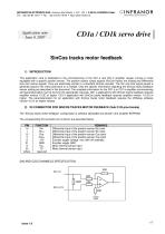
SERVO DRIVES & MOTION CONTROL INFRANOR ELECTRONICS SAS • Avenue Jean Moulin • B.P. 142 • F-65104 LOURDES Cedex Application note June 4, 2007 CDla / CDlk servo drive |SinCos tracks motor feedback1) INTRODUCTION This application note is dedicated to the commissioning of the CD1-a and CD1-k amplifier ranges running a motor equipped with a specific position sensor. The position sensor output signals (SinCos tracks) are analog and differential sine and cosine signals. They are electrically similar to a standard SinCos encoder. The Sin and Cos signal period is generally equal to the motor pole pitch or a multiple. Only the specific information regarding the SinCos tracks feedback sensor setting are described in this document. The complete information for the CD1 -a or CD1 -k amplifier commissioning and parameterization can be found in the appropriate manuals. CD1-a applications with SinCos tracks feedback requires amplifier version 12.3C or higher. CD1-k application with SinCos tracks feedback requires amplifier version 112.33 or higher. The parameterization for an application with SinCos tracks motor feedback requires the VDSetup software version 4.0 or an higher release. The “SinCos tracks motor feedback” configuration is software selectable and stored in the amplifier EEPROM. The corresponding X3 connector pin functions are described below.
Open the catalog to page 1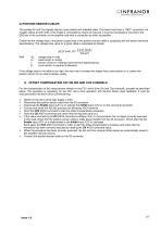
SERVO DRIVES & MOTION CONTROL The analog Sin and Cos signals require a pair twisted and shielded cable. The shield must have a "360°" connection via metallic collars at both ends. If the shield is connected by means of a pig tail, it must be connected at one end to the GND pin of the connector on the amplifier side with a connection as short as possible. Check that the voltage drop in the power supply lines of the position sensor cable is complying with the sensor technical specifications. The voltage drop value for a given cable is calculated as follows: AU: voltage drop in volts Lc: cable length...
Open the catalog to page 2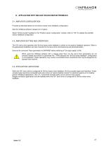
CD1-a/CD1-k ranges: SinCos tracks motor feedback 5) APPLICATION WITH SIN/COS TRACKS MOTOR FEEDBACK 5-1. AMPLIFIER CONFIGURATION Proceed as described below for the SinCos tracks motor feedback configuration: Start the VDSetup software (release 4.0 or higher). Select "SinCos tracks" feedback in the "Position sensor configuration" window. Click on "OK" to validate the amplifier sensor feedback configuration. 5-2. AMPLIFIER SETTING AND OPERATION The CD1 servo drive operation with SinCos tracks motor feedback is similar to the resolver feedback operation. Refer to the appropriate Installation and...
Open the catalog to page 3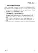
SERVO DRIVES & MOTION CONTROL For the compensation of the position sensor errors (offsets and amplitude difference between the Sin and Cos tracks), proceed as described below. This operation allows to reduce the motor speed ripples at high speed and improve the positioning accuracy. It is required when the application performances must be optimized. In this case, the SinCos tracks error compensation operation must be renewed if the motor position sensor is changed for maintenance. > Start the servo drive commissioning and parameterization according to the appropriate CD1 amplifier Intallation...
Open the catalog to page 4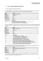
SERVO DRIVES & MOTION CONTROL The motor feedback sensor is used to close the servo motor torque and speed control loops. The servo motor position loop can be closed by the motor feedback sensor or with the second sensor (see object 306Ah). In order to avoid running the motor feedback programming procedure by mistake, it is only executed when a specific signature is written to this object. The signature is 'fdbk'.
Open the catalog to page 5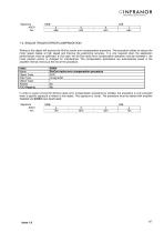
SERVO DRIVES & MOTION CONTROL
Open the catalog to page 6
SERVO DRIVES & MOTION CONTROL The following hardware indexes are required in the CD1-a and CD1 -k amplifiers in order to support the SinCos tracks motor feedback functionality.
Open the catalog to page 7All Infranor Group catalogs and technical brochures
 XtrapulsPac_EN
4 Pages
 SMTBSi-2Tz_en_2.1
43 Pages
 PacSimBox_d_1
1 Page
 Pac-SF01_flyer_en_18.02
4 Pages
 Pac_User_1.2.1.218
253 Pages
 Pac_Templates_en_1.9
27 Pages
 Pac_STO_Installation_en_2.2
13 Pages
 Pac_SF01_operating_en_1.6
63 Pages
 Pac_SF01_EN
4 Pages
 Pac_Installation_en_2.23
82 Pages
 Pac_flyer_en_17.12
4 Pages
 Option_CT_EMF
6 Pages
 MOVINOR_LH055_LH086_LH097_LH142
23 Pages
 ma_series
6 Pages
 GemSafeTorqueOff_en_1.1
12 Pages
 CD1pm_e_1.2(old)
18 Pages
 CD1pInst_e_7.2(old)
35 Pages
 CD1kInst_e_4.1(old)
40 Pages
 CD1k_CANopenProtocol_e_1.3(old)
86 Pages
 CD1a_e_7.1(old)
45 Pages
 Catalogue gamme SMT-BD1
11 Pages
 BM20A(F)v3_0
20 Pages
 BM20A(D)v3_0
20 Pages
 BF400(GB)v2_2
21 Pages
 BF400(D)v2_2
21 Pages
 BF230(GB)v2_0
23 Pages
 BF230(F)v2_0
23 Pages
 BD2m_e_2.2
69 Pages
 BD2m(GB)2.0
70 Pages
 BD2_e_3.2
53 Pages
 BD2(GB)3.1
53 Pages
 BD2(D)3.1
54 Pages
 Movinor_LH_e
4 Pages
 ma_series
6 Pages
 BD1t(GB)3.1
81 Pages
 BD1t(F)3.0
85 Pages
 BD1pInst(GB)3.0
25 Pages
 BD1pInst(F)3.0
23 Pages
 BD1pInst(D)3.0
24 Pages
 BD1pCD1pUse_e_2.4
57 Pages
 BD1m(GB)5.0
58 Pages
 BD1m(F)5.0
57 Pages
 BD1m(D)v3_3
64 Pages
 BD1k(GB)2.1
35 Pages
 BD1k(F)2.1
36 Pages
 BD1j(GB)v2_41
19 Pages
 BD1j(F)v2_4
21 Pages
 BD1i(GB)v2_21
23 Pages
 BD1i(F)v2_2
27 Pages
 BD1h(F)3.0
65 Pages
 BD1h(D)3.0
59 Pages
 BD1g(GB)v3_0
28 Pages
 BD1g(F)v3_0
28 Pages
 BD1a400(GB)v2_3
43 Pages
 BD1a400(F)v2_3
44 Pages
 BD1a400(D)v2_3
45 Pages
 BD1(GB)7.1_noPW
45 Pages
 BD1(GB)7.1
45 Pages
 BD1(F)7.1_noPW
47 Pages
 BD1(F)7.1
47 Pages
 BD1(D)7.1
45 Pages
 BD1 Katalog
11 Pages
 Easy_User_5.0.1.60.2
190 Pages
 01ma_smv_e_01953
40 Pages
 PacHP-SF_Flyer_en_23.06
4 Pages
 IRD_User_Manual_en_1.2.XX.54.rev_b
216 Pages
 PacHP_User_en_1.2.8.100.b
280 Pages
 PacHP_SF02_operating_en_1.6
103 Pages
 PacHP_SF01_operating_en_2.0
63 Pages
 PacHP_Installation_en_2.9
91 Pages
 PacHP_Series_Brochure
8 Pages
 PacHP_Flyer_us_20.10
4 Pages
 IRD_Installation_en_1.5
42 Pages
 Easy_STO_en_1.4
14 Pages
 Easy_DB_STO_en_1.2
14 Pages
 Easy_DB_Installation_en_1.4
36 Pages
 CD1pmUser_en_4.2
55 Pages
 CD1pmInst_en_8.15
40 Pages
 CD1k_CANopenProtocol_en_2.10.1.1
108 Pages
 CD1pm_ProfibusProtocol_en_1.5
50 Pages
 CD1kUser_en_2.3
26 Pages
 CD1a_en_8.17
62 Pages
 CD1kInst_en_5.16
46 Pages
 CD1_STO_en_1.8
16 Pages
 CD1_flyer_en_14.09
4 Pages
 Braking_Resistors_en_1.5
10 Pages
 XtracontrolDC2_EN
4 Pages
 Flyer_VisiTouchCNC_EN_V1.1-1
2 Pages
 XtraforsWashdown_EN-2024
2 Pages
 DataSheet_CybIO_CNC_V1.0
6 Pages
 XtraforsPrime_EN-2024
2 Pages
 XtraforsMSS_EN
4 Pages
 XtraforsMSA_EN_2024
2 Pages
 XtraforsEx_EN-2024
2 Pages
 XtraforsBR_EN-2024
2 Pages
 XtraforsBL_EN-2024
2 Pages
 XtraforsBC-ed01-vs3
4 Pages
 Manual_XtraforsPrime
46 Pages
 Drawing_1
1 Page
 Datasheet_MSS
5 Pages
 Datasheet_2
2 Pages
 Datasheet_1
4 Pages
 BLSBLT_series
2 Pages
 BL220221
2 Pages
 BL270
BL2702 Pages
 BL190
BL1902 Pages
 bl100_series
6 Pages
 bl40_series
6 Pages
 BL30
BL302 Pages
 2019-01_XtraforsFP-DSL_FR
4 Pages
 Movinor_T_EN
4 Pages
 Movinor_N_EN
4 Pages
 Movinor_Low_Voltage_EN
4 Pages
 Manual Movinor T 03-2026
46 Pages
 Manual Movinor N 03-2026
63 Pages
 XtrapulsEasy™ AC servo-drive
4 Pages
 XtrapulsCD1 AC servo-drives
4 Pages
 CybIO
CybIO6 Pages
 AC SERVOMOTORS
2 Pages
 Movinor® N AC Servomotors
4 Pages






Archived catalogs
 AN_CD1ak_AbsoluteEncoder_en_2.0
10 Pages
 AN_CD1pm_AbsoluteEncoder_en_2.0
10 Pages
 AN_CD1pm_SinCosTracks_e_1.0
7 Pages
 AN_DC_bus_interfacing_en_1.3
5 Pages
 CD1_EC_conformity_24.05
1 Page
 CD1_STO_conformity_19.02
2 Pages
 EtherCAT Interface_en_1.3
20 Pages
 Easy_EC_Conformity_24_10
1 Page
 GDPS_EC_conformity_24.07
1 Page
 IRD_EC_Conformity_25.03
1 Page
 PacHP_TÜV_certificate_25.07
2 Pages
 BD1c(F)v2_01
19 Pages
 BD1c(GB)v2_01
19 Pages
 BD1d(F)v2_01
25 Pages
 BD1d(GB)v2_01
25 Pages
 BD1e(F)v2_01
22 Pages
 BD1f(F)v2_01
17 Pages
 BD1f(GB)v2_01
18 Pages
 Pac_EC_conformity_25.04
1 Page




















