
- Catalogs
- Infranor Group
- CD1a_en_8.17


CD1a_en_8.17

CD1a_en_8.17
The document serves as a comprehensive manual for the XtrapulsCD1-a™ series of digital servo drives, designed for brushless AC motors. It emphasizes the importance of thoroughly reading the manual before operation to ensure proper storage, usage, and commissioning.
The manual details technical specifications for different models, including XtrapulsCD1-a-230/I and XtrapulsCD1-a-400/I, and compliance with CE and UL standards, ensuring safety and performance.
Key safety instructions include precautions against electrostatic discharge (ESD), proper storage conditions, and waiting for residual voltage to dissipate before handling. It also covers risks of burns from hot surfaces and proper disposal of electronic waste in compliance with WEEE regulations.
Guidelines for the disposal of INFRANOR products are provided, classifying them under WEEE and detailing the recycling process through RECYLUM in France, stressing the importance of selective disposal to comply with environmental regulations.
Detailed instructions for connection and wiring of the drives are provided, including diagrams for different models and configurations, and requirements for UL compliance.
The document outlines steps for commissioning the drives, including initial power-up procedures and configuration settings, emphasizing correct parameter settings for optimal performance.
Maintenance should be performed by skilled technicians, with unauthorized interventions voiding the warranty. The manual reserves the right to change information without notice, highlighting the importance of consulting the latest version.
The XtrapulsCD1-a series are all-digital PWM servo drives designed for speed control of AC sinusoidal motors with position sensors, available as standalone units with integrated power supplies and mains filters.
Specifications include operation on 230 VAC or 400/480 VAC, integrated braking systems, and support for various sensor configurations. Compliance with EMC and UL standards is ensured.
Detailed troubleshooting steps for various faults and operating problems are included, along with service and maintenance procedures to ensure optimal performance.
Specifications for continuous RMS power for single-phase voltage are provided, ensuring a capacitor lifetime of 20,000 hours.
Output voltage range and current options are specified, with detailed specifications for each drive type.
Both drive versions include regulation loops for current, speed, and position, integrated mains filter, and various encoder inputs.
Maximum room temperature is 40°C, with specific reductions in rated currents above this temperature. Drives are designed for vertical mounting in a closed cabinet.
Protections for various errors are outlined, including drive rated current overload and position feedback cable interruption.
Detailed dimensions and mandatory vertical mounting instructions are provided, along with specifications for braking resistors.
Connector locations and specifications for resolver, command, logic inputs-outputs, and encoder connections are detailed.
The drives comply with CE certification and various EMC and electrical standards, with specified environmental conditions and mounting requirements.
Detailed procedures for configuring and connecting components are provided, including software-selectable configurations stored in EEPROM.
Adherence to standards such as EN61000.4-2-3-4-5 and EN55011 is detailed, with recommendations for shielding and managing leakage current.
Detailed pin functions for various connectors are provided, emphasizing user responsibility for source-side protection.
Guidelines emphasize using twisted and shielded cables, ensuring ground wiring, and maintaining shield continuity.
Cables must withstand high voltage and temperature, with specific recommendations for cable types and fastening torque.
Installers must use UL listed quick connects for ground connections, with specific requirements for auxiliary supply input and recommended fuse types.
Diagrams for different drive models are provided, emphasizing the use of UL listed quick connects and copper conductors.
The VISUAL DRIVE SETUP software allows easy modification of drive parameters, with specific procedures for auto-tuning.
Initial checks and power-on procedures are outlined to avoid damage, with communication established via RS 232.
Instructions for configuring feedback sensors and adjusting parameters for specific applications are provided.
All parameters should be saved to the drive EEPROM to ensure configurations are retained after power cycles.
Configuration steps for motors equipped with a resolver are outlined, with specific settings for position sensor and auto-tuning.
Solutions for common axis movement issues are provided, including adjustments for motor noise and direction.
Details on utilizing a second position sensor for master axis displacement measurement and adjusting position scaling factors are included.
Steps for addressing various system faults are provided, including checking connections and using software for identification.
Troubleshooting and maintenance procedures for position mode errors and operational issues are detailed.
Steps to address a following error in the position loop are provided, including load compatibility and position loop adjustments.
Solutions for common operating problems are outlined, including motor movement issues and noise problems.
Procedures for replacing a drive and transferring parameters are provided.
Details on hardware adjustments and resolver connections are included.
Instructions for motor thermal sensor connections and I2t protection modes are provided.
Details on the use of limit switch inputs and various outputs are provided.
Information on encoder output resolution and its relation to motor speed is included.
Details on resolution values for the output encoder and related parameters are provided.
Configuration for analog current limit reversal is detailed.
Various gains and filters used in the servo controller are described, with auto-tuning procedures outlined.
Support for multi-axis connections via serial links is detailed, with address assignment instructions.
The feature for reducing disturbances in brushless motors is explained, with procedures for data acquisition and saving.
Details on the power feedback system using a braking resistor are provided.
Information on the ordering code for Xtrapuls CD1 drives is provided, including operation voltage and current ratings.
Infranor Group offers motion solutions with a global presence, focusing on customer productivity and competitive advantages.
Catalog excerpts
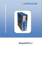
DIGITAL SERVO DRIVES FOR BRUSHLESS AC MOTORS
Open the catalog to page 1
! This is a general manual describing a series of servo drives having output capability suitable for driving AC brushless sinusoidal servo motors. Instructions for storage, use after storage, commissioning as well as all technical details require the MANDATORY reading of the manual before getting the drives operational. Maintenance procedures should be attempted only by highly skilled technicians having good knowledge of electronics and servo systems with variable speed (EN 60204-1 standard) and using proper test equipment. The compliance with the standards and the "CE" approval is only valid...
Open the catalog to page 2
Information and sorting instructions regarding INFRANOR Waste category Recyclable waste Recyclable waste Recyclable waste Recyclable waste Electronical boards and components WEEE (Waste Electronic and Electrical Equipment) Dangerous industrial waste Waste management Waste disposal centre / collection point of recyclable waste Waste disposal centre / collection point of recyclable waste Waste disposal centre / metal collection point Waste disposal centre / metal collection point France: http://www.ecosystem.eco/fr/sousrubrique/solutions Abroad: Country-specific regulation Sorting instructions...
Open the catalog to page 3
OINFRANOr PAGE 2.1.3 - Common specifications to both drive versions XtrapulsCD1-a-230/I and XtrapulsCD1-a- 3.3 - X2: COMMAND CONNECTOR, LOGIC INPUTS-OUTPUTS AND ENCODER (Sub D 25 PINS
Open the catalog to page 4
Chapter 1 - General description 1.1 - INTRODUCTION Series XtrapulsCD1-a all-digital servo modules are PWM servo drives that provide speed control for AC sinusoidal motors (brushless) equipped with a position sensor. The XtrapulsCD1-a system is available as a stand-alone single-axis block including all supplies as well as the mains filters, and is 230 VAC or 400/480 VAC mains operated. 1.2 - DESCRIPTION / COMPLIANCE WITH THE STANDARDS 1.2.1 - General description The XtrapulsCD1-a drive directly controls the motor torque and speed by means of the information provided by a high resolution position...
Open the catalog to page 7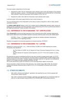
The power supply is depending on the drive type: XtrapulsCD1-a-230/I: 230 VAC single-phase mains operation power supply with limitation of the operation power (see chapter 2, section 1.1) or three-phase via a transformer or an autotransformer or three-phase mains operation if there are three-phase mains available in 200 to 230 VAC. XtrapulsCD1-a-400/I: 400 to 480 VAC three-phase mains operated power supply. A soft start system of the power supply limits the inrush current at power on. The very small dimensions of the XtrapulsCD1-a drive allow an optimum integration in 300 mm deep cabinets (connectors...
Open the catalog to page 8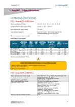
External 100 Ohm / 100 W resistor (dp 100/100) Minimum resistance: 50 Ohm (dp 50/200) Mains operating power supply Isolated galvanic auxiliary supply voltage Motor phase-phase output voltage Integrated braking system Minimum inductance between phases Drive type Maximum room temperature = 40° C. Continuous RMS power ensuring a capacitor lifetime of 20 000 hours:
Open the catalog to page 9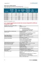
OINFRANOr DRIVE OUTPUT CURRENT RATINGS Output voltage range for 400-480 VAC (rms) three-phase mains. Output current range: 1.8 A, 2.7 A, 5.1 A, 7.2 A, 14 A, 30 A, 45 A, 70 A, 90 A (rms)
Open the catalog to page 10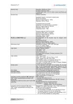
OINFRANOIT Resolver input
Open the catalog to page 11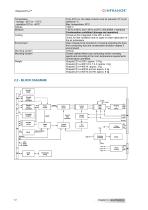
OINFRANOr Temperature
Open the catalog to page 12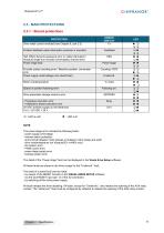
OINFRANOIT 2.3 - MAIN PROTECTIONS 2.3.1 - Stored protections PROTECTION The power stage error includes the following faults: - power supply overvoltage - internal switch protection - short-circuit between motor phases or between motor phase and earth - drive overtemperature (on XtrapulsCD1-a-400/I only) - power stage supply error - braking system error The detail of the “Power stage” fault can be displayed in the Visual drive Setup software. All these faults are stored in the drive except for the "Undervolt." fault. The reset of a stored fault can be made: - by means of the RESET function in...
Open the catalog to page 13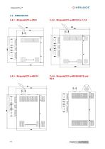
XtrapulsCDI-a™ OINFRANOr
Open the catalog to page 14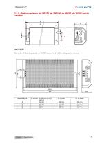
Connection of the braking resistor dp 16.5/560 on pins 1 and 3 of the braking resistor connector
Open the catalog to page 15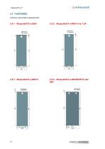
OINFRANOr2.5 - FASTENING VERTICAL MOUNTING IS MANDATORY
Open the catalog to page 16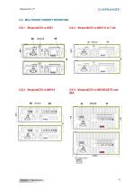
2.6 - MULTIAXES CABINET MOUNTING
Open the catalog to page 17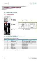
OINFRANOr 3.1 - CONNECTORS LOCATION3.1.1 - Drive connectors 3.2 - X1: RESOLVER CONNECTOR (Sub d 9 pins female) Same connector for both 230 V and 400 V ranges. For other resolver connections, see chapter 8 (Appendix), section 2.
Open the catalog to page 18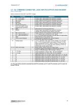
OINFRANOR93.3 - X2: COMMAND CONNECTOR, LOGIC INPUTS-OUTPUTS AND ENCODER (Sub D 25 pins male) Same connector for both 230 V and 400 V ranges. (1): The sum of the currents consumed by both X2 connector, pin 21, and X3 connector, pin 10, must not exceed 150 mA.
Open the catalog to page 19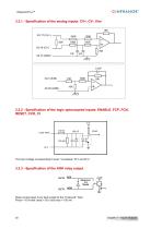
3.3.1 - Specification of the analog inputs: CV+, CV-, Ilim 16K X2-17 (CV+) 20K 3.3.2 - Specification of the logic optocoupled inputs: ENABLE, FCP, FCN, RESET, CVO, CI 5V Logic input The input voltage corresponding to level 1 is between 18 V and 30 V. 3.3.3 - Specification of the AOK relay output Relay contact open if any fault except for the "Undervolt." fault. Pmax = 10 W with Umax = 50 V and Imax = 100 mA
Open the catalog to page 20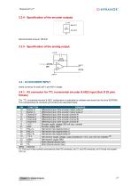
OINFRANOIT 3.3.4 - Specification of the encoder outputs -+5V 3.4 - X3 ENCODER INPUT Same connector for both 230 V and 400 V ranges. The “TTL incremental encoder & HES” configuration is selectable by software and stored into the drive EEPROM. The corresponding X3 connector pin functions are described below. (1): The sum of the currents consumed by both X2 connector, pin 21, and X3 connector, pin 10,must not exceed 150 mA.
Open the catalog to page 21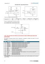
OIN F RANOR® ENCODER INPUT LINES SPECIFICATION There is no braking resistor on the former versions. HALL SENSORS INPUT LINES SPECIFICATION 3.4.2 - X3 connector for SinCos incremental encoder & HES input (Sub D 25 pins female) The “ SinCos incremental encoder & HES” configuration is selectable by software and stored in the drive EEPROM. The corresponding X3 connector pin functions are described below. (1): The sum of the currents consumed by both X2 connector, pin 21, and X3 connector, pin 10, must not exceed 150 mA.
Open the catalog to page 22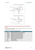
OINFRANOIT Sin/Cos encoder channels specification Hall sensors input lines specification 3.4.3 - X3 connector for absolute single-turn SinCos encoder (Sub D 25 pins female) The “ Absolute single-turn SinCos Encoder” configuration (Heidenhain ERN 1085 or compliant) is selectable by software and stored in the drive EEPROM. The corresponding X3 connector pin functions are described below.
Open the catalog to page 23All Infranor Group catalogs and technical brochures
 XtrapulsPac_EN
4 Pages
 SMTBSi-2Tz_en_2.1
43 Pages
 PacSimBox_d_1
1 Page
 Pac-SF01_flyer_en_18.02
4 Pages
 Pac_User_1.2.1.218
253 Pages
 Pac_Templates_en_1.9
27 Pages
 Pac_STO_Installation_en_2.2
13 Pages
 Pac_SF01_operating_en_1.6
63 Pages
 Pac_SF01_EN
4 Pages
 Pac_Installation_en_2.23
82 Pages
 Pac_flyer_en_17.12
4 Pages
 Option_CT_EMF
6 Pages
 MOVINOR_LH055_LH086_LH097_LH142
23 Pages
 ma_series
6 Pages
 GemSafeTorqueOff_en_1.1
12 Pages
 CD1pm_e_1.2(old)
18 Pages
 CD1pInst_e_7.2(old)
35 Pages
 CD1kInst_e_4.1(old)
40 Pages
 CD1k_CANopenProtocol_e_1.3(old)
86 Pages
 CD1a_e_7.1(old)
45 Pages
 Catalogue gamme SMT-BD1
11 Pages
 BM20A(F)v3_0
20 Pages
 BM20A(D)v3_0
20 Pages
 BF400(GB)v2_2
21 Pages
 BF400(D)v2_2
21 Pages
 BF230(GB)v2_0
23 Pages
 BF230(F)v2_0
23 Pages
 BD2m_e_2.2
69 Pages
 BD2m(GB)2.0
70 Pages
 BD2_e_3.2
53 Pages
 BD2(GB)3.1
53 Pages
 BD2(D)3.1
54 Pages
 Movinor_LH_e
4 Pages
 ma_series
6 Pages
 BD1t(GB)3.1
81 Pages
 BD1t(F)3.0
85 Pages
 BD1pInst(GB)3.0
25 Pages
 BD1pInst(F)3.0
23 Pages
 BD1pInst(D)3.0
24 Pages
 BD1pCD1pUse_e_2.4
57 Pages
 BD1m(GB)5.0
58 Pages
 BD1m(F)5.0
57 Pages
 BD1m(D)v3_3
64 Pages
 BD1k(GB)2.1
35 Pages
 BD1k(F)2.1
36 Pages
 BD1j(GB)v2_41
19 Pages
 BD1j(F)v2_4
21 Pages
 BD1i(GB)v2_21
23 Pages
 BD1i(F)v2_2
27 Pages
 BD1h(F)3.0
65 Pages
 BD1h(D)3.0
59 Pages
 BD1g(GB)v3_0
28 Pages
 BD1g(F)v3_0
28 Pages
 BD1a400(GB)v2_3
43 Pages
 BD1a400(F)v2_3
44 Pages
 BD1a400(D)v2_3
45 Pages
 BD1(GB)7.1_noPW
45 Pages
 BD1(GB)7.1
45 Pages
 BD1(F)7.1_noPW
47 Pages
 BD1(F)7.1
47 Pages
 BD1(D)7.1
45 Pages
 BD1 Katalog
11 Pages
 Easy_User_5.0.1.60.2
190 Pages
 01ma_smv_e_01953
40 Pages
 PacHP-SF_Flyer_en_23.06
4 Pages
 IRD_User_Manual_en_1.2.XX.54.rev_b
216 Pages
 PacHP_User_en_1.2.8.100.b
280 Pages
 PacHP_SF02_operating_en_1.6
103 Pages
 PacHP_SF01_operating_en_2.0
63 Pages
 PacHP_Installation_en_2.9
91 Pages
 PacHP_Series_Brochure
8 Pages
 PacHP_Flyer_us_20.10
4 Pages
 IRD_Installation_en_1.5
42 Pages
 Easy_STO_en_1.4
14 Pages
 Easy_DB_STO_en_1.2
14 Pages
 Easy_DB_Installation_en_1.4
36 Pages
 CD1pmUser_en_4.2
55 Pages
 CD1pmInst_en_8.15
40 Pages
 CD1k_CANopenProtocol_en_2.10.1.1
108 Pages
 CD1pm_ProfibusProtocol_en_1.5
50 Pages
 CD1kUser_en_2.3
26 Pages
 CD1kInst_en_5.16
46 Pages
 CD1_STO_en_1.8
16 Pages
 CD1_flyer_en_14.09
4 Pages
 Braking_Resistors_en_1.5
10 Pages
 XtracontrolDC2_EN
4 Pages
 Flyer_VisiTouchCNC_EN_V1.1-1
2 Pages
 XtraforsWashdown_EN-2024
2 Pages
 DataSheet_CybIO_CNC_V1.0
6 Pages
 XtraforsPrime_EN-2024
2 Pages
 XtraforsMSS_EN
4 Pages
 XtraforsMSA_EN_2024
2 Pages
 XtraforsEx_EN-2024
2 Pages
 XtraforsBR_EN-2024
2 Pages
 XtraforsBL_EN-2024
2 Pages
 XtraforsBC-ed01-vs3
4 Pages
 Manual_XtraforsPrime
46 Pages
 Drawing_1
1 Page
 Datasheet_MSS
5 Pages
 Datasheet_2
2 Pages
 Datasheet_1
4 Pages
 BLSBLT_series
2 Pages
 BL220221
2 Pages
 BL270
BL2702 Pages
 BL190
BL1902 Pages
 bl100_series
6 Pages
 bl40_series
6 Pages
 BL30
BL302 Pages
 2019-01_XtraforsFP-DSL_FR
4 Pages
 Movinor_T_EN
4 Pages
 Movinor_N_EN
4 Pages
 Movinor_Low_Voltage_EN
4 Pages
 Manual Movinor T 03-2026
46 Pages
 Manual Movinor N 03-2026
63 Pages
 XtrapulsEasy™ AC servo-drive
4 Pages
 XtrapulsCD1 AC servo-drives
4 Pages
 CybIO
CybIO6 Pages
 AC SERVOMOTORS
2 Pages
 Movinor® N AC Servomotors
4 Pages






Archived catalogs
 AN_CD1ak_AbsoluteEncoder_en_2.0
10 Pages
 AN_CD1ak_SinCosTracks_e_1.0
7 Pages
 AN_CD1pm_AbsoluteEncoder_en_2.0
10 Pages
 AN_CD1pm_SinCosTracks_e_1.0
7 Pages
 AN_DC_bus_interfacing_en_1.3
5 Pages
 CD1_EC_conformity_24.05
1 Page
 CD1_STO_conformity_19.02
2 Pages
 EtherCAT Interface_en_1.3
20 Pages
 Easy_EC_Conformity_24_10
1 Page
 GDPS_EC_conformity_24.07
1 Page
 IRD_EC_Conformity_25.03
1 Page
 PacHP_TÜV_certificate_25.07
2 Pages
 BD1c(F)v2_01
19 Pages
 BD1c(GB)v2_01
19 Pages
 BD1d(F)v2_01
25 Pages
 BD1d(GB)v2_01
25 Pages
 BD1e(F)v2_01
22 Pages
 BD1f(F)v2_01
17 Pages
 BD1f(GB)v2_01
18 Pages
 Pac_EC_conformity_25.04
1 Page




















