
- Catalogs
- Infranor Group
- CD1a_e_7.1(old)


CD1a_e_7.1(old)

CD1a_e_7.1(old)
The manual is for servo speed amplifiers designed for AC brushless sinusoidal servo motors. It highlights the need for skilled technicians for maintenance and emphasizes safety precautions, such as waiting five minutes after power down due to residual voltage risks. Compliance with standards and CE approval depends on proper installation as per the manual's recommendations.
The manual details specifications for amplifier models CD1-a-230/I and CD1-a-400/I, including mains supply, auxiliary supply, motor output voltage, and maximum room temperature. Common specifications include digital current and speed regulation loops, a transmitter resolver position sensor, and a PWM switching frequency of 10 kHz. The amplifiers comply with EMC standards and are "CE" marked and "cULus" listed.
This section describes the location and specifications of connectors, including resolver, command, logic inputs-outputs, encoder, serial link, auxiliary supply, and power connectors. It provides detailed specifications for analog inputs, logic optocoupled inputs, relay outputs, and encoder outputs.
The manual provides connection diagrams for different amplifier models and discusses wiring requirements, including earth wiring and connector shield connections. It also covers compliance with UL standards, detailing connection methods and power supply requirements.
Instructions for amplifier standard configuration, first powering, and commissioning are provided. The section includes guidance on communication via serial link, amplifier adjustment, speed loop adjustment, and parameter saving.
The document lists potential faults and operating problems, such as system faults, motor issues, and noise problems, along with troubleshooting steps for each. It emphasizes checking connections, ensuring correct component orientation, and using the VISUAL DRIVE SETUP software for fault resolution.
When replacing an amplifier, transfer EEPROM parameters and perform offset compensation. Hardware adjustments include resolver transformation ratio and EEPROM parameters. Instructions for adjusting to various resolver types and motor thermal sensors are provided.
Installers must use UL-listed quick connects for ground connections on drives with FASTON sockets. A 24 VDC isolated power supply, protected by a 4 A UL-listed fuse, is required for auxiliary supply input. The document recommends using twisted and shielded cables for analog input commands and ensuring proper polarity in wiring.
Catalog excerpts
SERVO DRIVES & MOTION CONTROL digital drive for AC sinusoidal brushless motors
Open the catalog to page 1
! This is a general manual describing a series of servo speed amplifiers having output capability suitable for driving AC brushless sinusoidal servo motors. This manual may be used in conjunction with appropriate and referenced drawings pertaining to the various specific models. Maintenance procedures should be attempted only by highly skilled technicians having good knowledge of electronics and servo systems with variable speed (EN 60204-1 standard) and using proper test equipment. The conformity with the standards and the "CE" approval is only valid if the items are installed according to the...
Open the catalog to page 3
Chapter 1 - General description 1- INTRODUCTION Series CD1-a all digital servo modules are PWM servo amplifiers that provide speed control for AC sinusoidal motors (brushless) with transmitter resolver. The CD1-a system is available as a stand-alone single-axis block including all supplies as well as the mains filter, and is 230 VAC or 400/480 VAC mains operated. 2 – DESCRIPTION / COMPLIANCE WITH THE STANDARDS 2.1 - GENERAL DESCRIPTION The CD1-a amplifier directly controls the motor torque and speed by means of the information provided by a transmitter resolver sensor. The motor speed or torque...
Open the catalog to page 7
CD1-a 2.2 - REFERENCE TO THE STANDARDS: "CE" CERTIFICATION The CD1-a amplifiers have been approved for their conformity with the EMC standards concerning the power servos referenced in the EN 61800.3 standard regarding "electrical power servos with variable speed": • EN 55011, Group 1, Class A regarding conducted and radiated radioelectric disturbances, • EN 61000.4-2-3-4-5 regarding immunity. Standard to be applied to the electrical equipments of industrial machines: EN 60204.1. The amplifiers have been "CE" marked since year 2000. 2.3 - REFERENCE TO THE STANDARDS: "UL" LISTING CD1-a series...
Open the catalog to page 8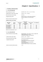
CINFRANOR SERVO DRIVES & MOTION CONTROL 1 - TECHNICAL SPECIFICATIONS 1.1 - CD1-a-230/I AMPLIFIER External 100 Ohm / 100 W resistor (dp 100/100) Minimum resistance: 50 Ohm (dp 50/200) Mains operating power supply Isolated galvanic auxiliary supply voltage Motor phase-phase output voltage Integrated braking system Minimum inductance between phases Mains operating power supply voltage Isolated auxiliary supply voltage Motor phase-phase output voltage Integrated braking system Minimum inductance between phases 400 to 480 VAC + 10 %/- 15 % 3~, TN or TT system with earthed neutral point, 50 - 60 Hz...
Open the catalog to page 9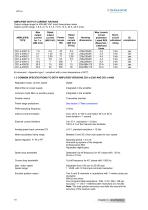
CINFRANOR AMPLIFIER OUTPUT CURRENT RATINGS Output voltage range for 400-480 VAC (rms) three-phase mains Output current range: 1.8 A, 2.7 A, 5.1 A, 7.2 A, 14 A, 30 A, 45 A (rms) Environment : Appendix type 1, compliant with a room temperature of 40°C. Regulation loops: current, speed Mains filter on power supply Common mode filter on auxiliary supply Position sensor Power stage protections Internal current limitation External current limitation Integrated in the amplifier Integrated in the amplifier Transmitter resolver See section 3 "Main protections" Imax: 20 % to 100 % and Irated: 20 % to 50...
Open the catalog to page 10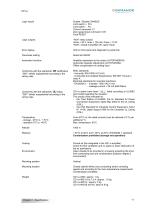
CINFRANOR Logic inputs Enable / Disable: ENABLE Limit switch - : FC-Current command: CI Zero speed input command: CV0 Fault RESET Logic outputs Error display Parameter setting Umax = 50 V, Imax = 100 mA, Pmax = 10 W "AOK": closed if amplifier OK, open if fault LED on front panel and diagnostic by serial link Automatic functions Amplifier adjustment to the motor (AUTOPHASING) Automatic regulator adjustment (AUTOTUNING) Offset compensation on analog input Conformity with the standards: CE certification EMC standards: "360°" shield; equipotential according to the - Immunity: EN 61000.4-2-3-4-5 wiring...
Open the catalog to page 11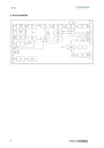
Enable Fault Resolver sensor conversion Pulse counter Sinusoidal oscillator Vector control Current input command Current loops Current monitors Encoder outputs Speed loop Current limitation Energy recuperation Input command Protections processing Ilim AOK Reset Enable Serial link Parameters saving
Open the catalog to page 12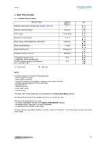
CINFRANOR 3 - MAIN PROTECTIONS 3.1 - STORED PROTECTIONS The power stage error includes the following faults: - power supply overvoltage - internal switch protection - short-circuit between motor phases or between motor phase and earth - amplifier overtemperature (on CD1-a-400/I only) - power stage supply - braking system The detail of the “Power stage” fault can be displayed in the Visual drive Setup software. All these faults are stored in the amplifier except for the "Undervolt." fault. The reset of a stored fault can be made: - by means of the RESET function in the VISUAL DRIVE SETUP software...
Open the catalog to page 13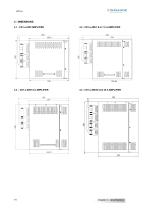
CINFRANOR - DIMENSIONS - CD1-a-230/I AMPLIFIER
Open the catalog to page 14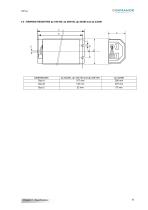
CINFRANOR 4.5 - BRAKING RESISTORS dp 100/100, dp 200/100, dp 50/200 and dp 33/280
Open the catalog to page 15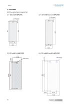
5 - FASTENING VERTICAL MOUNTING IS MANDATORY 5.1 - CD1-a-230/I AMPLIFIER
Open the catalog to page 16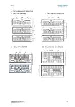
6 - MULTIAXES CABINET MOUNTING 6.1 - CD1-a-230/I AMPLIFIER
Open the catalog to page 17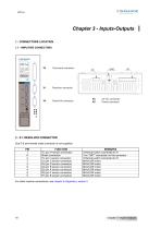
1 - CONNECTORS LOCATION 1.1 - AMPLIFIER CONNECTORS Command connector Serial link connector 2 - X1: RESOLVER CONNECTOR Sub D 9 pins female (male connector is not supplied) For other resolver connections, see chapter 8 (Appendix), section 2.
Open the catalog to page 18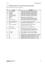
CINFRANOR 3 - X2: COMMAND CONNECTOR, LOGIC INPUTS-OUTPUTS AND ENCODER Sub D 25 pins male (female connector is not supplied)
Open the catalog to page 19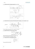
CD1-a 3.1 - SPECIFICATION OF THE ANALOG INPUTS: CV+, CV-, Ilim 4K 3.2 - SPECIFICATION OF THE LOGIC OPTOCOUPLED INPUTS: ENABLE, FCP, FCN, RESET, CVO, CI 5V 8.2 KΩ Logic input The input voltage corresponding to level 1 is between 18 V and 30V. 3.3 - SPECIFICATION OF THE "AOK" RELAY OUTPUT X2/18 AOK Relay contact open if any fault except for the "Undervolt." fault. Pmax = 10 W with Umax = 50 V and Imax = 100 mA 3.4 - SPECIFICATION OF THE ENCODER OUTPUTS +5V X2 - 5-7-9 CI 26LS31
Open the catalog to page 20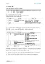
CINFRANOR 4 - X5 SERIAL LINK Sub D 9 pins male (female connector is not supplied) IMPORTANT: The motor cable must be shielded and connected over 360° on collars mounted for this purpose on the housing. The earth wire of the motor cable MUST be connected to the Faston socket marked with the GND sign. The earth reference must also be connected on the second Faston socket. ■ The installer of the drives has to use a UL Listed Quick connect for ground connection (0.250 inches or 6.35 mm wide nominal). ■ Field wiring terminals have to use copper conductors only. ■ Torque value for field wiring terminals:...
Open the catalog to page 21All Infranor Group catalogs and technical brochures
 XtrapulsPac_EN
4 Pages
 SMTBSi-2Tz_en_2.1
43 Pages
 PacSimBox_d_1
1 Page
 Pac-SF01_flyer_en_18.02
4 Pages
 Pac_User_1.2.1.218
253 Pages
 Pac_Templates_en_1.9
27 Pages
 Pac_STO_Installation_en_2.2
13 Pages
 Pac_SF01_operating_en_1.6
63 Pages
 Pac_SF01_EN
4 Pages
 Pac_Installation_en_2.23
82 Pages
 Pac_flyer_en_17.12
4 Pages
 Option_CT_EMF
6 Pages
 MOVINOR_LH055_LH086_LH097_LH142
23 Pages
 ma_series
6 Pages
 GemSafeTorqueOff_en_1.1
12 Pages
 CD1pm_e_1.2(old)
18 Pages
 CD1pInst_e_7.2(old)
35 Pages
 CD1kInst_e_4.1(old)
40 Pages
 CD1k_CANopenProtocol_e_1.3(old)
86 Pages
 Catalogue gamme SMT-BD1
11 Pages
 BM20A(F)v3_0
20 Pages
 BM20A(D)v3_0
20 Pages
 BF400(GB)v2_2
21 Pages
 BF400(D)v2_2
21 Pages
 BF230(GB)v2_0
23 Pages
 BF230(F)v2_0
23 Pages
 BD2m_e_2.2
69 Pages
 BD2m(GB)2.0
70 Pages
 BD2_e_3.2
53 Pages
 BD2(GB)3.1
53 Pages
 BD2(D)3.1
54 Pages
 Movinor_LH_e
4 Pages
 ma_series
6 Pages
 BD1t(GB)3.1
81 Pages
 BD1t(F)3.0
85 Pages
 BD1pInst(GB)3.0
25 Pages
 BD1pInst(F)3.0
23 Pages
 BD1pInst(D)3.0
24 Pages
 BD1pCD1pUse_e_2.4
57 Pages
 BD1m(GB)5.0
58 Pages
 BD1m(F)5.0
57 Pages
 BD1m(D)v3_3
64 Pages
 BD1k(GB)2.1
35 Pages
 BD1k(F)2.1
36 Pages
 BD1j(GB)v2_41
19 Pages
 BD1j(F)v2_4
21 Pages
 BD1i(GB)v2_21
23 Pages
 BD1i(F)v2_2
27 Pages
 BD1h(F)3.0
65 Pages
 BD1h(D)3.0
59 Pages
 BD1g(GB)v3_0
28 Pages
 BD1g(F)v3_0
28 Pages
 BD1a400(GB)v2_3
43 Pages
 BD1a400(F)v2_3
44 Pages
 BD1a400(D)v2_3
45 Pages
 BD1(GB)7.1_noPW
45 Pages
 BD1(GB)7.1
45 Pages
 BD1(F)7.1_noPW
47 Pages
 BD1(F)7.1
47 Pages
 BD1(D)7.1
45 Pages
 BD1 Katalog
11 Pages
 Easy_User_5.0.1.60.2
190 Pages
 01ma_smv_e_01953
40 Pages
 PacHP-SF_Flyer_en_23.06
4 Pages
 IRD_User_Manual_en_1.2.XX.54.rev_b
216 Pages
 PacHP_User_en_1.2.8.100.b
280 Pages
 PacHP_SF02_operating_en_1.6
103 Pages
 PacHP_SF01_operating_en_2.0
63 Pages
 PacHP_Installation_en_2.9
91 Pages
 PacHP_Series_Brochure
8 Pages
 PacHP_Flyer_us_20.10
4 Pages
 IRD_Installation_en_1.5
42 Pages
 Easy_STO_en_1.4
14 Pages
 Easy_DB_STO_en_1.2
14 Pages
 Easy_DB_Installation_en_1.4
36 Pages
 CD1pmUser_en_4.2
55 Pages
 CD1pmInst_en_8.15
40 Pages
 CD1k_CANopenProtocol_en_2.10.1.1
108 Pages
 CD1pm_ProfibusProtocol_en_1.5
50 Pages
 CD1kUser_en_2.3
26 Pages
 CD1a_en_8.17
62 Pages
 CD1kInst_en_5.16
46 Pages
 CD1_STO_en_1.8
16 Pages
 CD1_flyer_en_14.09
4 Pages
 Braking_Resistors_en_1.5
10 Pages
 XtracontrolDC2_EN
4 Pages
 Flyer_VisiTouchCNC_EN_V1.1-1
2 Pages
 XtraforsWashdown_EN-2024
2 Pages
 DataSheet_CybIO_CNC_V1.0
6 Pages
 XtraforsPrime_EN-2024
2 Pages
 XtraforsMSS_EN
4 Pages
 XtraforsMSA_EN_2024
2 Pages
 XtraforsEx_EN-2024
2 Pages
 XtraforsBR_EN-2024
2 Pages
 XtraforsBL_EN-2024
2 Pages
 XtraforsBC-ed01-vs3
4 Pages
 Manual_XtraforsPrime
46 Pages
 Drawing_1
1 Page
 Datasheet_MSS
5 Pages
 Datasheet_2
2 Pages
 Datasheet_1
4 Pages
 BLSBLT_series
2 Pages
 BL220221
2 Pages
 BL270
BL2702 Pages
 BL190
BL1902 Pages
 bl100_series
6 Pages
 bl40_series
6 Pages
 BL30
BL302 Pages
 2019-01_XtraforsFP-DSL_FR
4 Pages
 Movinor_T_EN
4 Pages
 Movinor_N_EN
4 Pages
 Movinor_Low_Voltage_EN
4 Pages
 Manual Movinor T 03-2026
46 Pages
 Manual Movinor N 03-2026
63 Pages
 XtrapulsEasy™ AC servo-drive
4 Pages
 XtrapulsCD1 AC servo-drives
4 Pages
 CybIO
CybIO6 Pages
 AC SERVOMOTORS
2 Pages
 Movinor® N AC Servomotors
4 Pages






Archived catalogs
 AN_CD1ak_AbsoluteEncoder_en_2.0
10 Pages
 AN_CD1ak_SinCosTracks_e_1.0
7 Pages
 AN_CD1pm_AbsoluteEncoder_en_2.0
10 Pages
 AN_CD1pm_SinCosTracks_e_1.0
7 Pages
 AN_DC_bus_interfacing_en_1.3
5 Pages
 CD1_EC_conformity_24.05
1 Page
 CD1_STO_conformity_19.02
2 Pages
 EtherCAT Interface_en_1.3
20 Pages
 Easy_EC_Conformity_24_10
1 Page
 GDPS_EC_conformity_24.07
1 Page
 IRD_EC_Conformity_25.03
1 Page
 PacHP_TÜV_certificate_25.07
2 Pages
 BD1c(F)v2_01
19 Pages
 BD1c(GB)v2_01
19 Pages
 BD1d(F)v2_01
25 Pages
 BD1d(GB)v2_01
25 Pages
 BD1e(F)v2_01
22 Pages
 BD1f(F)v2_01
17 Pages
 BD1f(GB)v2_01
18 Pages
 Pac_EC_conformity_25.04
1 Page




















