
- Catalogs
- Infranor Group
- BF230(GB)v2_0


BF230(GB)v2_0

BF230(GB)v2_0
The BF Rack manual provides guidance on racks for servo amplifiers used with AC brushless servo motors, emphasizing compliance with European standards and CE certification. Proper installation is crucial for maintaining conformity, and the manual advises waiting 30 seconds after power down before handling to avoid physical damage from electrical parts.
The manual outlines technical data such as rated DC bus voltage, AC input power voltages, and auxiliary power voltage. It specifies rated output currents for different versions (35 A, 70 A, 90 A) and details the braking system's triggering threshold and power ratings. Dimensions for components like the 6 axes BF Rack and external braking resistors are also included.
Instructions for rack backpanel connections are provided, with diagrams for serial and individual wiring of signals like AMP. READY and POWER READY. Proper wiring is emphasized to ensure functionality and safety.
The manual stresses adherence to standards such as EN 55011 for electromagnetic compatibility and EN 60204-1 for electrical equipment of industrial machines. CE marking has been in place since 1995, ensuring compliance with relevant directives.
Details for ordering the BF Rack and mains filter are provided, including options for fan size, braking resistor type, and axis location. A table helps select the appropriate configuration based on specific requirements.
Warnings and recommendations include ensuring proper cooling for braking resistors and maintaining a safe distance from flammable materials. Maintenance should be performed by skilled technicians.
EMC is emphasized, with a 360° shield connection for motor cables to the chassis using a clamping collar. Ground connections must adhere to safety standards, and motor cables should not be near input command and resolver cables.
For a 380V/400V three-phase power supply, a 380V/220V autotransformer is required. The auxiliary supply connects between two 220V phases at the autotransformer output. A connection diagram is provided, and all supply lines must be cut off to all poles in a three-phase connection. An insulation transformer can be used as an alternative.
A common mode inductance on the motor output and a mains filter for the auxiliary supply are needed to comply with EN 55011 standards. Grounding of the BF rack chassis is mandatory to prevent damage from defective mains insulation, and warranty is void if these requirements are not met.
The mains filter is mandatory for CE certification compliance. It should be connected near the BF rack, with emphasis on equipotentiality through metallic braiding. Current ratings for the rack are specified as FT 35 (35 A) and FT 70 (70 A).
Wiring and ground connections must be carefully executed. Low potential cables should not be near high potential cables. Ground connections should be short, using braidings rather than wires. Shielded cables are required for input command, logic, motor, and sensor cables, with 360° shield connections at both ends.
The shield must remain uninterrupted over the entire cable length. Guidelines are provided for ensuring shield continuity using metallic or metal-plated connectors, emphasizing proper shield connections for EMC compliance.
Catalog excerpts
SERVO DRIVES & MOT/ON CONTROL
Open the catalog to page 1
OINFRANOR BFRACK
Open the catalog to page 2
This is a general manual describing a series of racks receiving servo amplifiers having output capability for driving AC brushless servo motors. This manual may be used in conjunction with appropriate and referenced drawings pertaining to the various specific models. Maintenance procedures should be attempted only by highly skilled technicians (EN 60 204.1 standard) using proper test equipment. The conformity with the standards and the "CE" approval are only valid if the items are installed according to the recommendations of the racks and amplifiers manuals. Any contact with electrical parts,...
Open the catalog to page 3
OINFRANOR BFRACK
Open the catalog to page 4
OINFRANOR BFRACK
Open the catalog to page 6
1 - COMPLIANCE WITH THE EUROPEAN STANDARDS: "CE" CERTIFICATION 1.1 - General description The rack type of the "B" series is "BF". The "F" means "floating" power bus voltage, because it is not referenced to the chassis. This range is ALWAYS equipped for rear mounting. The motor outputs and the supply inputs are ALWAYS on a terminal bar. The logic inputs - outputs of the X5 connector on the rack backpanel allow the serial connection of the AMP. READY and POWER READY signals. All connections are ALWAYS made on the top of the rack (power supply, motors, logics). The "BF" rack is operating with a...
Open the catalog to page 7
The "BF" rack answers the requirements of the EN 55011 standard regarding the electromagnetic compatibility, with optional input filter for the mains rejection. But the common mode filter of the motor output as well as the mains filter of the auxiliary supply are integrated in the rack, as standard. The fan must always be mounted on the top of the rack. The various fan types are depending on the amplifier continuous current. 1.2 - Reference to the standards The "B" series amplifiers mounted into the BF rack, which is equipped with the mains filter BF 35/70, have been approved for their conformity...
Open the catalog to page 8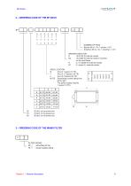
OINFRANOR sawd dunes & ucmctto coHnOi. NUMBER OF FANS — Big fan 90 l/s - Ex: 1 big fan = V01 Small fan 56 l/s - Ex: 1 small fan = V10 BRAKING RESISTOR D 15 0/140 W internal resistor _ D2 10 0/280 W external resistor mounted D1 2 x option E, external resistor AXES LOCATION 0 Axis of 1 space (12 TE) NOTE Decreasing current rating from left to right. The power supply requires 1 space (12 TE) FILTER SIZING 70 power supply rating
Open the catalog to page 9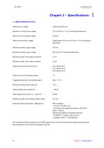
1 - MAIN TECHNICAL DATA Rated DC bus voltage Maximum AC input power voltage Minimum AC input power voltage Rated auxiliary power voltage Minimum auxiliary supply voltage Maximum auxiliary supply voltage Maximum section of the supply connector Maximum section of the motor connector Rated output current on the DC bus Output current of the auxiliary supply Triggering threshold of the braking system Minimum braking resistor (option E) Rated braking power (option D1) Peak braking power (max 1 s) - option D1 -Maximum section of the braking resistor cables Conformity with the standards - CE approval...
Open the catalog to page 10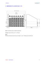
2 – DIMENSIONS OF A 6 AXES BF RACK, 12 TE NOTE: The heatsink does not modify the dimensions. Example: 6 axes rack: Axes 1 to 6 = 12 TE each. NOTE For other rack dimensions than 6 axes, see chapter 1, part 2: "Ordering code of the BF rack".
Open the catalog to page 11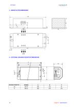
OINFRANOR SBWO DUNES & MOTION COHTK3L 4 - EXTERNAL BRAKING RESISTOR DIMENSIONS BRAKING RESISTOR
Open the catalog to page 12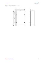
EXTERNAL BRAKING RESISTOR D1 (1100 W)
Open the catalog to page 13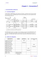
Chapter 3 – Connections 1 – RACK BACKPANEL CONNECTION 1.1 – Connection diagramm The AMP. READY, POWER READY and Idyn signals can be serially or individually wired for all axes according to the configuration below. The ENABLE signal can also be wired individually or as a common signal to all axes on the front panel connector X4. Last wired axis D POWER READY AMP. READY The jumpers A, B, N are located on the backpanel - see section 2 -. symbolizes the closed contact of the BD1 amplifier relays. The POWER READY signal is only available on the rack backpanel connector X5. If the POWER READY signal...
Open the catalog to page 14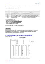
OINFRANOR As standard, all these signals are serially wired: jumpers A, N and B are closed on the last wired axis and switches D, E, F, G, H, O and P are all ON. The X5 connector allows to have: - the logic ENABLE signal common to all axes, - the POWER READY relay serially wired on all axes, - the AMP. READY relay serially wired on all axes, - the Idyn relay serially wired on all axes. SPECIFICATIONS: Umax : 50 V, Imax = 100 mA, Prated = 5 W. On some INFRANOR amplifier types, the Idyn relay may have another function, particularly the control of the motor brake relay on the ranges BD1/m, BD1/h,...
Open the catalog to page 15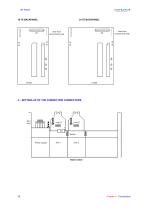
OINFRANOR 18 TE BACKPANEL SfffVD DIWES & MOJKM coxntot View from components side View from components side 3 - SETTING-UP OF THE CONNECTION CONNECTORS 16 Chapter 3 - Connections
Open the catalog to page 16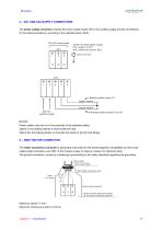
4 – XA1 AND XA2 SUPPLY CONNECTORS The power supply connector includes the power supply inputs (XA1), the auxiliary supply and the connections for the braking resistor(s), according to the selected option (XA2). 3x220 VAC three-phase supply max. section: 6 mm2 max. continuous current: 82 A Earth: Ø 5 screw Braking resistor option D1 Braking resistor options E and D1 NOTES Power cables must not run in the proximity of low potential cables. Option D: the braking resistor is wired inside the rack. Option D2: the braking resistor is mounted and wired on the left rack flange. 5 – XMOT MOTOR CONNECTOR...
Open the catalog to page 17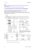
NOTE The conformity with the EMC standards requires the mandatory shielding of the motor cables, with a 360° connection at both ends. The motor cables must not run in the proximity of input command and resolver cables. 6 – THREE-PHASE CONNECTION VIA A 380V/220V (400V/230V) AUTOTRANSFORMER The 380 V / 400 V three-phase power supply requires the use of a 380 V / 220 V autotransformer. The 230 Vac phase/neutral connection is possible for the auxiliary supply. The auxiliary supply can be connected between two 220 V phases to the autotransformer OUTPUT The auxiliary supply is connected to the autotransformer...
Open the catalog to page 18All Infranor Group catalogs and technical brochures
 XtrapulsPac_EN
4 Pages
 SMTBSi-2Tz_en_2.1
43 Pages
 PacSimBox_d_1
1 Page
 Pac-SF01_flyer_en_18.02
4 Pages
 Pac_User_1.2.1.218
253 Pages
 Pac_Templates_en_1.9
27 Pages
 Pac_STO_Installation_en_2.2
13 Pages
 Pac_SF01_operating_en_1.6
63 Pages
 Pac_SF01_EN
4 Pages
 Pac_Installation_en_2.23
82 Pages
 Pac_flyer_en_17.12
4 Pages
 Option_CT_EMF
6 Pages
 MOVINOR_LH055_LH086_LH097_LH142
23 Pages
 ma_series
6 Pages
 GemSafeTorqueOff_en_1.1
12 Pages
 CD1pm_e_1.2(old)
18 Pages
 CD1pInst_e_7.2(old)
35 Pages
 CD1kInst_e_4.1(old)
40 Pages
 CD1k_CANopenProtocol_e_1.3(old)
86 Pages
 CD1a_e_7.1(old)
45 Pages
 Catalogue gamme SMT-BD1
11 Pages
 BM20A(F)v3_0
20 Pages
 BM20A(D)v3_0
20 Pages
 BF400(GB)v2_2
21 Pages
 BF400(D)v2_2
21 Pages
 BF230(F)v2_0
23 Pages
 BD2m_e_2.2
69 Pages
 BD2m(GB)2.0
70 Pages
 BD2_e_3.2
53 Pages
 BD2(GB)3.1
53 Pages
 BD2(D)3.1
54 Pages
 Movinor_LH_e
4 Pages
 ma_series
6 Pages
 BD1t(GB)3.1
81 Pages
 BD1t(F)3.0
85 Pages
 BD1pInst(GB)3.0
25 Pages
 BD1pInst(F)3.0
23 Pages
 BD1pInst(D)3.0
24 Pages
 BD1pCD1pUse_e_2.4
57 Pages
 BD1m(GB)5.0
58 Pages
 BD1m(F)5.0
57 Pages
 BD1m(D)v3_3
64 Pages
 BD1k(GB)2.1
35 Pages
 BD1k(F)2.1
36 Pages
 BD1j(GB)v2_41
19 Pages
 BD1j(F)v2_4
21 Pages
 BD1i(GB)v2_21
23 Pages
 BD1i(F)v2_2
27 Pages
 BD1h(F)3.0
65 Pages
 BD1h(D)3.0
59 Pages
 BD1g(GB)v3_0
28 Pages
 BD1g(F)v3_0
28 Pages
 BD1a400(GB)v2_3
43 Pages
 BD1a400(F)v2_3
44 Pages
 BD1a400(D)v2_3
45 Pages
 BD1(GB)7.1_noPW
45 Pages
 BD1(GB)7.1
45 Pages
 BD1(F)7.1_noPW
47 Pages
 BD1(F)7.1
47 Pages
 BD1(D)7.1
45 Pages
 BD1 Katalog
11 Pages
 Easy_User_5.0.1.60.2
190 Pages
 01ma_smv_e_01953
40 Pages
 PacHP-SF_Flyer_en_23.06
4 Pages
 IRD_User_Manual_en_1.2.XX.54.rev_b
216 Pages
 PacHP_User_en_1.2.8.100.b
280 Pages
 PacHP_SF02_operating_en_1.6
103 Pages
 PacHP_SF01_operating_en_2.0
63 Pages
 PacHP_Installation_en_2.9
91 Pages
 PacHP_Series_Brochure
8 Pages
 PacHP_Flyer_us_20.10
4 Pages
 IRD_Installation_en_1.5
42 Pages
 Easy_STO_en_1.4
14 Pages
 Easy_DB_STO_en_1.2
14 Pages
 Easy_DB_Installation_en_1.4
36 Pages
 CD1pmUser_en_4.2
55 Pages
 CD1pmInst_en_8.15
40 Pages
 CD1k_CANopenProtocol_en_2.10.1.1
108 Pages
 CD1pm_ProfibusProtocol_en_1.5
50 Pages
 CD1kUser_en_2.3
26 Pages
 CD1a_en_8.17
62 Pages
 CD1kInst_en_5.16
46 Pages
 CD1_STO_en_1.8
16 Pages
 CD1_flyer_en_14.09
4 Pages
 Braking_Resistors_en_1.5
10 Pages
 XtracontrolDC2_EN
4 Pages
 Flyer_VisiTouchCNC_EN_V1.1-1
2 Pages
 XtraforsWashdown_EN-2024
2 Pages
 DataSheet_CybIO_CNC_V1.0
6 Pages
 XtraforsPrime_EN-2024
2 Pages
 XtraforsMSS_EN
4 Pages
 XtraforsMSA_EN_2024
2 Pages
 XtraforsEx_EN-2024
2 Pages
 XtraforsBR_EN-2024
2 Pages
 XtraforsBL_EN-2024
2 Pages
 XtraforsBC-ed01-vs3
4 Pages
 Manual_XtraforsPrime
46 Pages
 Drawing_1
1 Page
 Datasheet_MSS
5 Pages
 Datasheet_2
2 Pages
 Datasheet_1
4 Pages
 BLSBLT_series
2 Pages
 BL220221
2 Pages
 BL270
BL2702 Pages
 BL190
BL1902 Pages
 bl100_series
6 Pages
 bl40_series
6 Pages
 BL30
BL302 Pages
 2019-01_XtraforsFP-DSL_FR
4 Pages
 Movinor_T_EN
4 Pages
 Movinor_N_EN
4 Pages
 Movinor_Low_Voltage_EN
4 Pages
 Manual Movinor T 03-2026
46 Pages
 Manual Movinor N 03-2026
63 Pages
 XtrapulsEasy™ AC servo-drive
4 Pages
 XtrapulsCD1 AC servo-drives
4 Pages
 CybIO
CybIO6 Pages
 AC SERVOMOTORS
2 Pages
 Movinor® N AC Servomotors
4 Pages






Archived catalogs
 AN_CD1ak_AbsoluteEncoder_en_2.0
10 Pages
 AN_CD1ak_SinCosTracks_e_1.0
7 Pages
 AN_CD1pm_AbsoluteEncoder_en_2.0
10 Pages
 AN_CD1pm_SinCosTracks_e_1.0
7 Pages
 AN_DC_bus_interfacing_en_1.3
5 Pages
 CD1_EC_conformity_24.05
1 Page
 CD1_STO_conformity_19.02
2 Pages
 EtherCAT Interface_en_1.3
20 Pages
 Easy_EC_Conformity_24_10
1 Page
 GDPS_EC_conformity_24.07
1 Page
 IRD_EC_Conformity_25.03
1 Page
 PacHP_TÜV_certificate_25.07
2 Pages
 BD1c(F)v2_01
19 Pages
 BD1c(GB)v2_01
19 Pages
 BD1d(F)v2_01
25 Pages
 BD1d(GB)v2_01
25 Pages
 BD1e(F)v2_01
22 Pages
 BD1f(F)v2_01
17 Pages
 BD1f(GB)v2_01
18 Pages
 Pac_EC_conformity_25.04
1 Page




















