- Catalogs
- Infranor Group
- BD2m_e_2.2


BD2m_e_2.2

BD2m_e_2.2
- Current Ratings: The document provides detailed current ratings for both 220 VAC and 400 VAC amplifier versions, including maximum authorized rated and continuous currents under different fan conditions.
- Conformity: The amplifiers conform to EMC standards (EN 55011, CEI 801) and electrical standards for industrial machines (EN 60204.1).
- Temperature Range: Storage from -20°C to +70°C, operation from 5°C to +40°C, with current reductions above 40°C.
- Other Specifications: Include PWM switching frequency, current loop bandwidth, and encoder input options.
- Analog Inputs/Outputs: The module features optoisolated inputs for various functions such as limit switches, run & phasing, and enable/disable commands. Analog outputs are available for monitoring purposes with a resolution of 12 bits.
- Logic Inputs/Outputs: Logic inputs and outputs are optocoupled, supporting functions like start, stop, jog, and speed control. The polarity of these inputs and outputs can be reversed via software parameters.
- Encoder Output: The encoder output provides differential signals for channels A, B, and marker Z, with programmable division ratios for channels A and B.
- Logic Outputs Connector: Features programmable outputs with a total current capacity of 350 mA for all outputs.
- Logic Inputs Connector: Supports multiple logic inputs with voltage levels between 5 V and 24 V.
- Wiring and Grounding: Emphasizes the importance of proper grounding and shielding to prevent interference, following CEI 801 and EN 55011 standards.
- Motor and Sensor Cables: Cables must be shielded to avoid common mode effects, with specific recommendations for analog inputs and serial link cables.
- Hardware Adjustments: Includes diagrams for setting jumpers related to current loops, motor thermal sensors, and communication protocols.
- Adjustable Parameters: Parameters can be set using the Visual Drive Setup software, requiring a PC with specific system requirements.
- Standard Configuration: Details the default jumper settings for various components, including encoder and commutation signals.
- Encoder and Sensor Configuration: Provides guidance on configuring the module for different types of encoders and Hall Effect Sensors.
- PTC Thermal Sensor: The default adjustment for the PTC thermal sensor resistor at 120°C is 3 kΩ, with PSTH-A set to 10 kΩ.
- NTC Thermal Sensor: For motors with an NTC thermal sensor, the amplifier configuration requires the OP jumper closed and MN jumper open. The default adjustment for the NTC thermal sensor resistor at 120°C is 3 kΩ, with PSTH-A set to 10 kΩ.
- 400 VAC Amplifier Version: Current loop adjustments depend on the motor and amplifier specifications. A selection table is provided for different amplifier current ratings (15 A to 100 A) and motor models.
- 220 VAC Amplifier Version: Similar adjustments are made for the 220 VAC version, with a detailed selection table for amplifier current ratings (4 A to 100 A) and motor models.
- Power Supply Testing: Ensure auxiliary and power supply voltages are within specified limits before operation.
- Amplifier Setup: Connect necessary cables and start the Visual Drive Setup software. Ensure proper serial communication between the PC and amplifier.
- Motor Hall Effect Sensors Adjustment: Verify correct wiring and jumper settings for Hall Effect Sensors. Execute a motor phasing procedure if necessary.
- Absolute Single Turn Sin/Cos Encoder Adjustment: Check wiring and jumper settings for Sin/Cos encoders. Ensure correct supply voltage and encoder resolution.
- Ensure correct motor selection, encoder resolution, speed limit, and current limits. Execute auto-tuning procedures, especially for motors with unbalanced loads.
- Save all parameters to the amplifier EEPROM. Use micro-switches to define amplifier addresses for communication with multiple amplifiers.
- Calculate motor encoder resolution, maximum speed, and linear speed using provided formulas. Adjust current phase lead based on motor torque constant.
- "°C MOTOR" Fault: Check thermal sensor configuration and connections.
- "UNDERVOLT." Fault: Verify power supply status and connections.
- "°C AMPLIFIER" Fault: Ensure fan and heatsink configurations are correct for rated current.
- "POWER STAGE" Fault: Inspect DC bus voltage, braking system, and motor wiring for issues.
- "HES" Fault: Confirm correct wiring and settings for incremental encoder and HES configurations.
- "ENCODER" Fault: Check encoder connections and settings; disable marker pulse if necessary.
- "COUNTING" Fault: Ensure encoder settings and connections are correct; disable counting protection if needed.
- "I2T" Fault: Verify rated current values and adjust as necessary.
- "POSITION" Fault: Adjust following error threshold for compatibility with operating cycle.
- "ADC" Fault: Check analog input wiring and perform offset compensation.
- Motor Supplied but No Torque: Check current parameters and input commands.
- Motor Does Not Move: Verify power supply, fuses, and signal wiring.
- Shaft Locked or Erratic Movements: Inspect encoder wiring and perform auto-phasing.
- Discontinuous Motor Rotation: Check phase cable connections.
- Loud Noise in Motor: Ensure proper ground connections and mechanical transmission rigidity.
- Limit Switches and "CVO" Inputs: Describes the function of limit switches in stopping motor displacement.
- "AMP. READY" and "POWER READY" Outputs: Details the behavior of outputs during fault conditions.
- Following Error Protection: Explains the detection and response to position following errors.
- I²t Protection: Outlines current limitation procedures in fusing mode.
Catalog excerpts
SBUOUWEi. MOTION CONTCOt CINFRANOR SERVO DRIVES & MOTION CONTROL POSITIONER FOR SINUSOIDAL BRUSHLESS LINEAR AND ROTATING AC MOTORS
Open the catalog to page 1
! This is a general manual describing a series of servo amplifiers having output capability suitable for driving AC brushless sinusoidal servo motors. Instructions for storage, use after storage, commissioning as well as all technical details require the MANDATORY reading of the manual before getting the amplifiers operational. Maintenance procedures should be attempted only by highly skilled technicians having good knowledge of electronics and servo systems with variable speed (EN 60204-1 standard) and using proper test equipment. The conformity with the standards and the "CE" approval is only...
Open the catalog to page 2
smo DOVES l MOTION CONJUOL
Open the catalog to page 3
SERVO DRIVES & MOTION CONTROL
Open the catalog to page 4
smo DOVES l MOTION CONJUOL
Open the catalog to page 5
___________________________________BLANK PAGE_______________________________ ___________________________________BLANK PAGE_______________________________
Open the catalog to page 6
CHAPTER 1 - GENERAL DESCRIPTION 1 - INTRODUCTION Series SMT-BD2/m digital servo modules are sinusoidal PWM power amplifiers that provide position, speed and torque/force control for AC brushless motors (rotating or linear) equipped with encoder only or encoder with Hall Effect Sensors (HES) for the position feedback. The SMT-BD2/m digital servo drive is 220 VAC or 400 VAC main operated. The SMT-BD2/m plug-in system with 400 VAC power supply is available as a multiaxis version that can receive up to three axes in a standard 19" rack including the power supply. The SMT-BD2/m plug-in system with...
Open the catalog to page 7
OINFRANOR3 - REFERENCE TO THE STANDARDS The 220 VAC version of the SMT-BD2/m amplifiers operating in the BF rack, which is equipped with the mains filter BF-35 or 70, has been approved for its conformity with the Electromagnetic Compatibility standards: • EN 55011, Group 1, Class A regarding the conducted and radiated radioelectric disturbances, The 400 VAC version of the SMT-BD2/m amplifiers operating in the BF-400 rack, which is equipped with the mains filter F400-35 or 70, has been approved for its conformity with the Electromagnetic Compatibility standards: • EN 55011, Group 1, Class A regarding...
Open the catalog to page 8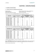
1.1 - Current ratings for the 220 VAC amplifier version Auxiliary supply voltage 310 VDC ( 200 VDC < Uaux < 340 VDC max.) Motor terminal to terminal output voltage 200 Vrms for 310 VDC bus Authorized output currents for current pulse mode operation (I2t protection in fusing mode) * Maximum ambient temperature = + 40° C, fan 1 = 56 l/s, fan 2 = 90 l/s. Note: The SMT-BD2/m-X/Xr amplifier types are equipped with an additional heatsink in order to improve the heat dissipation and increase their rated current. The width of these amplifier types is then 18 TE instead of 12 TE. Minimum inductance between...
Open the catalog to page 9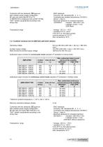
OINFRANOR Conformity with the standards: CE approval with multiaxis power supply configuration BF rack and mains filter BF-35 or 70, or SMTB.M 20 A single-axis rack and BF 35 filter. "360°" shields; equipotential according to the wiring rules. Temperature range Immunity: CEI standards 801- 2 - 3 - 4 Conducted and radiated disturbances: EN 55011, Group 1, class A - Electrical standards for industrial machines: - Leakage current > 3 mA (EMI filters) From 40°C on, the rated currents must be reduced of 3 %/°C. 1.2 - Current ratings for the 400 VAC amplifier version Auxiliary supply voltage 310 VDC...
Open the catalog to page 10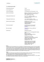
1.3 - OTHER SPECIFICATIONS PWM switching frequency Current loop bandwidth Cut-off frequency for 45° phase shift > 1 kHz Internal current limitation Maximum current range : 20 % to 100 % of Imax Rated current range : 20 % to 50 % of Imax Imax = amplifier current rating Analog torque limitation input 0 V to 10 V, resolution = 12 bits 100 % to 0 % of the torque set point value No limitation for 0 Volt Analog speed limitation input ±10 V, standard resolution = 12 bits 100 % to 0.1 % of the maximum speed value Speed and position regulator Sampling period = 0,5 ms Anti-wind-up system of the integrator...
Open the catalog to page 11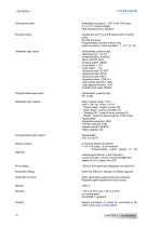
OINFRANOR Hall sensors input Encoder output Dedicated logic inputs Programmable logic inputs Dedicated logic outputs Programmable logic outputs Monitor outputs digitizing Error display Parameter setting Automatic functions Selectable by jumpers : 120° or 60° HES type 5 V or 15 V supply voltage HES sequence error detection Quadrature and TTL A & B signals with Z marker pulse Programmable encoder division ratio output resolution / input resolution : 1, 1/2, 1/4, 1/8 Optoisolated, positive logic, response time = 0.5 ms : •Enable/Disable: ENABLE •Servo On/Off: RUN •Homing switch: INDEX •Limit switch...
Open the catalog to page 12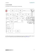
2 - BLOCK DIAGRAM The SMT-BD2/m servo module block diagram is presented below. Supply voltages Encoder input Pulses counter Vector control Current loops Encoder divider Position controller Current limitation Current Mes Sequences controller Current Limit Power supply SPEED LIMIT X4 TORQUE LIMIT Serial link Drive parameters The PR8 and PR10 connectors are not accessible for direct wiring; they are plugged on the BM20A single-axis rack or on the multiaxis BF rack according to the SMT-BD2/m amplifier housing (see chapter 3).
Open the catalog to page 13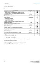
OINFRANOR 3 - MAIN PROTECTIONS 3.1 - Displayed protections PROTECTION All these faults are memory stored in the amplifier except for the "Undervolt." fault. The reset of a stored fault can be made: - by means of the RESET function in the Visual Drive Setup software - via the fault RESET input (pin 13 of the X4 connector) - by switching off the amplifier power supply.
Open the catalog to page 14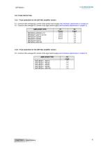
CINFRANOR 3.2 - Fuse protection F1 : Control of the average DC current of the power board supply (see Hardware adjustments in chapter 5). F2 : Control of the average DC current of the logic board supply (see Hardware adjustments in chapter 5).
Open the catalog to page 15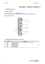
SERVO DRIVES & MOTION CONTROL For the 400 VAC amplifier version, see BF-400 RACK manual. For the 220 VAC amplifier version, see SMTB.M 20 A SINGLE-AXIS RACK manual or BF RACK manual. Faults display Encoder sensor Serial link Command Encoder output Command Analog inputs 2 - X5 SERIAL LINK CONNECTOR (Sub D 9 pins male) CHAPTER 3 - Inputs - Outputs
Open the catalog to page 16All Infranor Group catalogs and technical brochures
 XtrapulsPac_EN
4 Pages
 XtrapulsGemTemplates_e_1.4
21 Pages
 XtrapulsGem_User_Manual_v1.2.0.64
199 Pages
 XtrapulsGem_Inst_e_2.1
42 Pages
 XtrapulsGem_Inst_e_2.0
42 Pages
 SMTBSi-2Tz_en_2.1
43 Pages
 smt-100
32 Pages
 PacSimBox_d_1
1 Page
 Pac-SF01_flyer_en_18.02
4 Pages
 Pac_User_1.2.1.218
253 Pages
 Pac_Templates_en_1.9
27 Pages
 Pac_STO_Installation_en_2.2
13 Pages
 Pac_SF01_operating_en_1.6
63 Pages
 Pac_SF01_EN
4 Pages
 Pac_Installation_en_2.23
82 Pages
 Pac_flyer_en_17.12
4 Pages
 Option_CT_EMF
6 Pages
 MOVINOR_LH055_LH086_LH097_LH142
23 Pages
 ma_series
6 Pages
 GemSafeTorqueOff_en_1.1
12 Pages
 GemProgramming_e_1.1
47 Pages
 GDPS_old_version_1.1_1
11 Pages
 CD1pm_e_1.2(old)
18 Pages
 CD1pInst_e_7.2(old)
35 Pages
 CD1kInst_e_4.1(old)
40 Pages
 CD1k_CANopenProtocol_e_1.3(old)
86 Pages
 CD1a_e_7.1(old)
45 Pages
 Catalogue gamme SMT-BD1
11 Pages
 BM20A(F)v3_0
20 Pages
 BM20A(D)v3_0
20 Pages
 BF400(GB)v2_2
21 Pages
 BF400(D)v2_2
21 Pages
 BF230(GB)v2_0
23 Pages
 BF230(F)v2_0
23 Pages
 BD2m(GB)2.0
70 Pages
 BD2_e_3.2
53 Pages
 BD2(GB)3.1
53 Pages
 BD2(D)3.1
54 Pages
 Movinor_LH_e
4 Pages
 ma_series
6 Pages
 BD1t(GB)3.1
81 Pages
 BD1t(F)3.0
85 Pages
 BD1pInst(GB)3.0
25 Pages
 BD1pInst(F)3.0
23 Pages
 BD1pInst(D)3.0
24 Pages
 BD1pCD1pUse_e_2.4
57 Pages
 BD1m(GB)5.0
58 Pages
 BD1m(F)5.0
57 Pages
 BD1m(D)v3_3
64 Pages
 BD1k(GB)2.1
35 Pages
 BD1k(F)2.1
36 Pages
 BD1j(GB)v2_41
19 Pages
 BD1j(F)v2_4
21 Pages
 BD1i(GB)v2_21
23 Pages
 BD1i(F)v2_2
27 Pages
 BD1h(F)3.0
65 Pages
 BD1h(D)3.0
59 Pages
 BD1g(GB)v3_0
28 Pages
 BD1g(F)v3_0
28 Pages
 BD1a400(GB)v2_3
43 Pages
 BD1a400(F)v2_3
44 Pages
 BD1a400(D)v2_3
45 Pages
 BD1(GB)7.1_noPW
45 Pages
 BD1(GB)7.1
45 Pages
 BD1(F)7.1_noPW
47 Pages
 BD1(F)7.1
47 Pages
 BD1(D)7.1
45 Pages
 BD1 Katalog
11 Pages
 08ma_ms_e_01700
20 Pages
 Easy_User_5.0.1.60.2
190 Pages
 08ma_mrm_em_01575
20 Pages
 01ma_smv_e_01953
40 Pages
 PacHP-SF_Flyer_en_23.06
4 Pages
 IRD_User_Manual_en_1.2.XX.54.rev_b
216 Pages
 PacHP_User_en_1.2.8.100.b
280 Pages
 PacHP_SF02_operating_en_1.6
103 Pages
 PacHP_SF01_operating_en_2.0
63 Pages
 PacHP_Installation_en_2.9
91 Pages
 PacHP_Series_Brochure
8 Pages
 PacHP_Flyer_us_20.10
4 Pages
 IRD_Installation_en_1.5
42 Pages
 GDPS_Installation_en_4.4
18 Pages
 Easy_STO_en_1.4
14 Pages
 Easy_DB_STO_en_1.2
14 Pages
 Easy_DB_Installation_en_1.4
36 Pages
 CD1pmUser_en_4.2
55 Pages
 CD1pmInst_en_8.15
40 Pages
 CD1k_CANopenProtocol_en_2.10.1.1
108 Pages
 CD1pm_ProfibusProtocol_en_1.5
50 Pages
 CD1kUser_en_2.3
26 Pages
 CD1a_en_8.17
62 Pages
 CD1kInst_en_5.16
46 Pages
 CD1_STO_en_1.8
16 Pages
 CD1_flyer_en_14.09
4 Pages
 Braking_Resistors_en_1.5
10 Pages
 XtracontrolDC2_EN
4 Pages
 Flyer_VisiTouchCNC_EN_V1.1-1
2 Pages
 XtraforsWashdown_EN-2024
2 Pages
 DataSheet_CybIO_CNC_V1.0
6 Pages
 XtraforsPrime_EN-2024
2 Pages
 XtraforsMSS_EN
4 Pages
 XtraforsMSA_EN_2024
2 Pages
 XtraforsEx_EN-2024
2 Pages
 XtraforsBR_EN-2024
2 Pages
 XtraforsBL_EN-2024
2 Pages
 XtraforsBC-ed01-vs3
4 Pages
 Manual_XtraforsPrime
46 Pages
 Drawing_1
1 Page
 Datasheet_MSS
5 Pages
 Datasheet_2
2 Pages
 Datasheet_1
4 Pages
 BLSBLT_series
2 Pages
 BL220221
2 Pages
 BL270
BL2702 Pages
 BL190
BL1902 Pages
 bl100_series
6 Pages
 bl40_series
6 Pages
 BL30
BL302 Pages
 2019-01_XtraforsFP-DSL_FR
4 Pages
 Movinor_T_EN
4 Pages
 Movinor_N_EN
4 Pages
 Movinor_Low_Voltage_EN
4 Pages
 Manual Movinor T 03-2026
46 Pages
 Manual Movinor N 03-2026
63 Pages
 XtrapulsEasy™ AC servo-drive
4 Pages
 XtrapulsCD1 AC servo-drives
4 Pages
 CybIO
CybIO6 Pages
 AC SERVOMOTORS
2 Pages
 Movinor® N AC Servomotors
4 Pages






Archived catalogs
 AN_CD1ak_AbsoluteEncoder_en_2.0
10 Pages
 AN_CD1ak_SinCosTracks_e_1.0
7 Pages
 AN_CD1pm_AbsoluteEncoder_en_2.0
10 Pages
 AN_CD1pm_SinCosTracks_e_1.0
7 Pages
 AN_DC_bus_interfacing_en_1.3
5 Pages
 CD1_EC_conformity_24.05
1 Page
 CD1_STO_conformity_19.02
2 Pages
 EtherCAT Interface_en_1.3
20 Pages
 Easy_EC_Conformity_24_10
1 Page
 GDPS_EC_conformity_24.07
1 Page
 IRD_EC_Conformity_25.03
1 Page
 PacHP_TÜV_certificate_25.07
2 Pages
 BD1c(F)v2_01
19 Pages
 BD1c(GB)v2_01
19 Pages
 BD1d(F)v2_01
25 Pages
 BD1d(GB)v2_01
25 Pages
 BD1e(F)v2_01
22 Pages
 BD1f(F)v2_01
17 Pages
 BD1f(GB)v2_01
18 Pages
 CE_conformity_Gem
1 Page
 Pac_EC_conformity_25.04
1 Page
 Pac_GDPS_CEconformity
1 Page
![SMT100D_e_1.01[1]](https://img.directindustry.com/pdf/repository_di/4620720/smt100d-e-101-1-1141223_1mg.jpg) SMT100D_e_1.01[1]
SMT100D_e_1.01[1]40 Pages
 STO_declaration_Gem
2 Pages