
- Catalogs
- Infranor Group
- BD2(D)3.1


BD2(D)3.1

BD2(D)3.1
Catalog excerpts
CINFRANOR SERVO DRIVES & MOTION CONTROL DIGITALREGLER ZUM BETRIEB VON DREHSTROMSERVOMOTOREN
Open the catalog to page 1
ALLGEMEINE SICHERHEITSINFORMATIONEN ! Diese Betriebsanleitung Drehstromservomotoren. Das sorgfältige Lesen der Betriebssanleitung ist für das Lagern, den Einsatz nach Lagerung, die Inbetriebnahme sowie sämtliche technische Einzelheiten zu gewährleisten. Nur qualifiziertes Personal darf mit Betrieb und Wartung der Geräte beauftragt werden, d.h. Personen mit entsprechender Ausbildung, Erfahrung in Elektronik und Servosystemen mit variabler Drehzahl (EN 60 204-1 – Norm). Die Normgerechtheit sowie die CE-Zertifikation sind nur dann gültig, wenn die Geräte gemäß den Anweisungen der Betriebssanleitungen...
Open the catalog to page 3
SERVO DRIVES & MOTION CONTROL
Open the catalog to page 6
Kapitel 1 – Allgemeine Einsatzbedingungen 1 - VORWORT Die digitalen Servoregler der Baureihe SMT-BD2 sind für den Drehzahl- sowie Drehmoment/Kraft-Betrieb von bürstenlosen Motoren mit sinusförmiger Ausgangsspannung und Encoder allein bzw. Encoder mit Halleffektsensoren (HES) zur Positionsrückmeldung konzipiert. Der Drehmoment/Kraft-Sollwert ist eine analoge Signalspannung von +/- 10 V. Der SMT-BD2-Einschubregler verfügt über direkte 220 VAC bzw. 400 VAC-Netzeinspeisung. Die 400 VACBaureihe eignet sich zum Betrieb in einem mehrachsigen 19''-Rack von maximal 6 Achsen mit integriertem Netzteil....
Open the catalog to page 7
3 – GERÄTESPEZIFISCHE NORMEN Die im - mit BF 35/70-Netzfilter versehenen - BF-Rack betriebenen SMT-BD2-Servorregler mit 220 VACEinspeisung sind gemäß folgenden EMV-Normen zugelassen worden: - EN 55011, Gruppe 1, Klasse A (geleitete und gestrahlte radioelektrische Störungen), - CEI 801 - 2 - 3 - 4 (Störfestigkeit). Die im - mit Netzfilter FN 612-20/06 bzw. 356-16/06 versehenen - Einachsrack BM20A - BMM05F - BMM05AF betriebenen SMT-BD2-Servorregler mit 220 VAC-Einspeisung sind gemäß folgenden EMV-Normen zugelassen worden: - EN 55011, Gruppe 1, Klasse A (geleitete und gestrahlte radioelektrische...
Open the catalog to page 8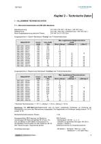
Motor-Ausgangsspannung zwischen Phasen 200 Veff fur 310 VDC-Bus Ausgangsstrome in "Sperre"-Betriebsart ("Fusing") der I2t-Sicherheitsfunktion * Maximale Raumtemperatur = + 40° C, Luftertyp 1 = 56 l/s, Luftertyp 2 = 90 l/s. Bemerkung: Die SMT-BD2-X/Xr-Reglermodule sind mit einem zusatzlichen Kuhlkorper zur Erhohung der Warmeabfuhr und somit des Nennstromes ausgestattet. anstatt 12 TE. Mindestinduktivitat zwischen Phasen Normgerechtheit: CE-Zulassung bei Betrieb im mehrachsigen BF-Rack mit Netzfilter BF-35 bzw. 70-, bzw. bei Betrieb im SMT-BM20 A-Einachsrack mit mit Netzfiltern FN 612-20/06, FN...
Open the catalog to page 9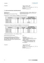
Ab 40°C sind die Nennstrome um 3 %/°C zu reduzieren. Betriebsspannung DC-Bus 565 VDC (480 VDC < DC-Bus < 685 VDC max.) Motor-Ausgangsspannung zwischen Phasen 380 Veff fur 565 VDC-Bus Ausgangsstrome in "Sperre"-Betriebsart ("Fusing") der I2t-Sicherheitsfunktion Mindestinduktivitat zwischen Phasen Normgerechtheit: CE-Zulassung bei Betrieb im mehrachsigen BF-Rack mit BF 35 bzw. 70-Netzfilter, bzw. bei Betrieb im SMT-BM20 A-Einachsrack mit BF35-Filter. 360°-Abschirmungen, Aquipotential gemaft Anschluftanweisungen. - Geleitete und gestrahlte Storungen: EN 55011, Gruppe 1, Klasse A Elektrische Normen...
Open the catalog to page 10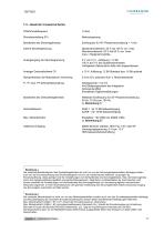
1.3 – SONSTIGE TECHNISCHE DATEN PWM-Pendelfrequenz Interne Strombegrenzung Spitzenstrombereich: 20 % bis 100 % von Imax Nennstrombereich: 20 % bis 50 % von Imax Imax = Reglerstromgröße. 0 V bis 10 V, Auflösung = 12 Bit 100 % bis 0 % des Spitzenstromwertes. Verfügbarer Spitzenstrom falls nicht angeschlossen. ± 10 V; Auflösung: 12 Bit Standard bzw. 16 Bit optional 0 s bis 30 s zwischen Null- u. Maximaldrehzahl Abtastperiode = 0,5 ms Anti-Sättigungssystem des Integrators Antiresonanzfilter Einstellbare Digitalverstärkungen Wählbare Eckfrequenz für 45°-Phasenverschiebung: 50 Hz, 75 Hz bzw. 100 Hz...
Open the catalog to page 11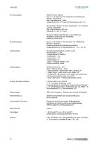
Mittels Brücken wählbar: Zwei A- u. B-Signale in TTL-Quadratur mit Z-Nullimpuls RS 422 - line receiver Max. Impulsfrequenz: 1 MHz Auflösung: 500 bis 106 Imp/U (EPROM-Version ab 7.1C) Inkrementaler Sin/Cos-Encoder Heidenhain 1 Vcc Sin/CosTyp bzw. kompatibel Max. Signalfrequenz: 500 KHz Auflösung: 103 bis 106 Imp./U. Absoluter Sin/Cos-Encoder über eine Umdrehung Heidenhain ERN 1085 oder kompatibel Auflösung: 2048 Imp/U. Zwei A- u. B-Kanäle in TTL-Quadratur mit Z-Nullimpuls RS 422 – line driver Programmierbares Encoderteilungsverhältnis Ausgangsauflösung / Eingangsauflösung: 1, 1/2, 1/4, 1/8 Optogekoppelte...
Open the catalog to page 12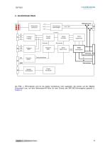
PWMLeistungsteil Leistungs- PR U Versorgung 10 Drehzahl rampe Serielle Schnittstelle Regler Parameter Die PR8- u. PR10-Stecker sind für die direkte Verdrahtung nicht zugänglich. Sie werden auf den BM20AEinachsrack bzw. auf dem Mehrachsen-BF-Rack (je nach Einsatz des SMT-BD2-Servoreglers) gesteckt (s. Kapitel 3). Kapitel 2 – Technische Daten
Open the catalog to page 13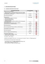
OINFRANOR 3 - SICHERHEITSFUNKTIONEN 3.1 - ANGEZEIGTE SICHERHEITSFUNKTIONEN Samtliche oben aufgefuhrte Fehler sind - mit Ausnahme des "Undervolt."-Fehlers - im Regler gespeichert. Die Ruckstellung eines gespeicherten Fehlers erfolgt: - mittels RESET-Funktion der VISUAL DRIVE SETUP-Software oder, - uber den RESET-Eingang (X4, Klemme 13) - durch ausschalten der Regler-Leistungsversorgung.
Open the catalog to page 14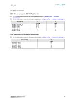
F1: DC-Durchschnittsstromkontrolle der Leistungskartenversorgung (s. Kapitel 5, Abs. 1: "Hardware-Einstellungen"). F2: DC-Durchschnittsstromkontrolle der Logikkartenversorgung (s. Kapitel 5, Abs. 1: "Hardware-Einstellungen"). Kapitel 2 - Technische Daten
Open the catalog to page 15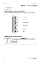
CINFRANOR SERVO DRIVES & MOTION CONTROL 1 - STECKERBELEGUNG1.1 - RACK-Stecker Fur die 400 VAC-Reglerbaureihe, s. Bedienungsanleitung BF/400-RACK. Fur die 220 VAC-Reglerbaureihe, s. Bedienungsanleitungen SMTB.M 20 A-EINACHSRACK bzw. BF-RACK. Serielle Schnittstelle
Open the catalog to page 16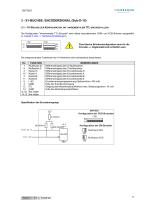
OINFRANOR3 - X1-BUCHSE: ENCODERSIGNAL (Sub-D-15) 3.1 - X1-BUCHSE ZUR KONFIGURATION MIT INKREMENTALEM TTL-ENCODER ALLEIN. Die Konfiguration "inkrementaler TTL-Encoder" wird mittels nachstehenden COM- und COD-Brucken ausgewahlt (s. Kapitel 5, Abs. 1: Hardware-Einstellungen). Eine falsche Bruckenkonfiguration kann fur die Encoder- u. Reglerelektronik schadlich sein. Die entsprechenden Funktionen der X1-Klemmen sind nachstehend beschrieben. Konfiguration der ZM-Bruecke [~~j]1 Nullimpuls EIN ZM
Open the catalog to page 17All Infranor Group catalogs and technical brochures
 XtrapulsPac_EN
4 Pages
 SMTBSi-2Tz_en_2.1
43 Pages
 PacSimBox_d_1
1 Page
 Pac-SF01_flyer_en_18.02
4 Pages
 Pac_User_1.2.1.218
253 Pages
 Pac_Templates_en_1.9
27 Pages
 Pac_STO_Installation_en_2.2
13 Pages
 Pac_SF01_operating_en_1.6
63 Pages
 Pac_SF01_EN
4 Pages
 Pac_Installation_en_2.23
82 Pages
 Pac_flyer_en_17.12
4 Pages
 Option_CT_EMF
6 Pages
 MOVINOR_LH055_LH086_LH097_LH142
23 Pages
 ma_series
6 Pages
 GemSafeTorqueOff_en_1.1
12 Pages
 CD1pm_e_1.2(old)
18 Pages
 CD1pInst_e_7.2(old)
35 Pages
 CD1kInst_e_4.1(old)
40 Pages
 CD1k_CANopenProtocol_e_1.3(old)
86 Pages
 CD1a_e_7.1(old)
45 Pages
 Catalogue gamme SMT-BD1
11 Pages
 BM20A(F)v3_0
20 Pages
 BM20A(D)v3_0
20 Pages
 BF400(GB)v2_2
21 Pages
 BF400(D)v2_2
21 Pages
 BF230(GB)v2_0
23 Pages
 BF230(F)v2_0
23 Pages
 BD2m_e_2.2
69 Pages
 BD2m(GB)2.0
70 Pages
 BD2_e_3.2
53 Pages
 BD2(GB)3.1
53 Pages
 Movinor_LH_e
4 Pages
 ma_series
6 Pages
 BD1t(GB)3.1
81 Pages
 BD1t(F)3.0
85 Pages
 BD1pInst(GB)3.0
25 Pages
 BD1pInst(F)3.0
23 Pages
 BD1pInst(D)3.0
24 Pages
 BD1pCD1pUse_e_2.4
57 Pages
 BD1m(GB)5.0
58 Pages
 BD1m(F)5.0
57 Pages
 BD1m(D)v3_3
64 Pages
 BD1k(GB)2.1
35 Pages
 BD1k(F)2.1
36 Pages
 BD1j(GB)v2_41
19 Pages
 BD1j(F)v2_4
21 Pages
 BD1i(GB)v2_21
23 Pages
 BD1i(F)v2_2
27 Pages
 BD1h(F)3.0
65 Pages
 BD1h(D)3.0
59 Pages
 BD1g(GB)v3_0
28 Pages
 BD1g(F)v3_0
28 Pages
 BD1a400(GB)v2_3
43 Pages
 BD1a400(F)v2_3
44 Pages
 BD1a400(D)v2_3
45 Pages
 BD1(GB)7.1_noPW
45 Pages
 BD1(GB)7.1
45 Pages
 BD1(F)7.1_noPW
47 Pages
 BD1(F)7.1
47 Pages
 BD1(D)7.1
45 Pages
 BD1 Katalog
11 Pages
 Easy_User_5.0.1.60.2
190 Pages
 01ma_smv_e_01953
40 Pages
 PacHP-SF_Flyer_en_23.06
4 Pages
 IRD_User_Manual_en_1.2.XX.54.rev_b
216 Pages
 PacHP_User_en_1.2.8.100.b
280 Pages
 PacHP_SF02_operating_en_1.6
103 Pages
 PacHP_SF01_operating_en_2.0
63 Pages
 PacHP_Installation_en_2.9
91 Pages
 PacHP_Series_Brochure
8 Pages
 PacHP_Flyer_us_20.10
4 Pages
 IRD_Installation_en_1.5
42 Pages
 Easy_STO_en_1.4
14 Pages
 Easy_DB_STO_en_1.2
14 Pages
 Easy_DB_Installation_en_1.4
36 Pages
 CD1pmUser_en_4.2
55 Pages
 CD1pmInst_en_8.15
40 Pages
 CD1k_CANopenProtocol_en_2.10.1.1
108 Pages
 CD1pm_ProfibusProtocol_en_1.5
50 Pages
 CD1kUser_en_2.3
26 Pages
 CD1a_en_8.17
62 Pages
 CD1kInst_en_5.16
46 Pages
 CD1_STO_en_1.8
16 Pages
 CD1_flyer_en_14.09
4 Pages
 Braking_Resistors_en_1.5
10 Pages
 XtracontrolDC2_EN
4 Pages
 Flyer_VisiTouchCNC_EN_V1.1-1
2 Pages
 XtraforsWashdown_EN-2024
2 Pages
 DataSheet_CybIO_CNC_V1.0
6 Pages
 XtraforsPrime_EN-2024
2 Pages
 XtraforsMSS_EN
4 Pages
 XtraforsMSA_EN_2024
2 Pages
 XtraforsEx_EN-2024
2 Pages
 XtraforsBR_EN-2024
2 Pages
 XtraforsBL_EN-2024
2 Pages
 XtraforsBC-ed01-vs3
4 Pages
 Manual_XtraforsPrime
46 Pages
 Drawing_1
1 Page
 Datasheet_MSS
5 Pages
 Datasheet_2
2 Pages
 Datasheet_1
4 Pages
 BLSBLT_series
2 Pages
 BL220221
2 Pages
 BL270
BL2702 Pages
 BL190
BL1902 Pages
 bl100_series
6 Pages
 bl40_series
6 Pages
 BL30
BL302 Pages
 2019-01_XtraforsFP-DSL_FR
4 Pages
 Movinor_T_EN
4 Pages
 Movinor_N_EN
4 Pages
 Movinor_Low_Voltage_EN
4 Pages
 Manual Movinor T 03-2026
46 Pages
 Manual Movinor N 03-2026
63 Pages
 XtrapulsEasy™ AC servo-drive
4 Pages
 XtrapulsCD1 AC servo-drives
4 Pages
 CybIO
CybIO6 Pages
 AC SERVOMOTORS
2 Pages
 Movinor® N AC Servomotors
4 Pages






Archived catalogs
 AN_CD1ak_AbsoluteEncoder_en_2.0
10 Pages
 AN_CD1ak_SinCosTracks_e_1.0
7 Pages
 AN_CD1pm_AbsoluteEncoder_en_2.0
10 Pages
 AN_CD1pm_SinCosTracks_e_1.0
7 Pages
 AN_DC_bus_interfacing_en_1.3
5 Pages
 CD1_EC_conformity_24.05
1 Page
 CD1_STO_conformity_19.02
2 Pages
 EtherCAT Interface_en_1.3
20 Pages
 Easy_EC_Conformity_24_10
1 Page
 GDPS_EC_conformity_24.07
1 Page
 IRD_EC_Conformity_25.03
1 Page
 PacHP_TÜV_certificate_25.07
2 Pages
 BD1c(F)v2_01
19 Pages
 BD1c(GB)v2_01
19 Pages
 BD1d(F)v2_01
25 Pages
 BD1d(GB)v2_01
25 Pages
 BD1e(F)v2_01
22 Pages
 BD1f(F)v2_01
17 Pages
 BD1f(GB)v2_01
18 Pages
 Pac_EC_conformity_25.04
1 Page




















