General Overview: The document is a comprehensive manual for the INFRANOR Unwinder/Rewinder Servo Drive with a PROFIBUS DP interface, specifically the SMT-BD1/t model. It provides detailed instructions on the operation, maintenance, and technical specifications of the servo amplifiers designed for AC brushless sinusoidal servo motors.
Warnings and Safety: The manual emphasizes the importance of reading the entire document before operating the amplifiers. It highlights the need for skilled technicians to handle maintenance and warns about potential physical damage from improper handling. Compliance with standards and proper installation are crucial for maintaining CE approval.
Specifications: The document outlines technical specifications, including current ratings for 220 VAC and 400 VAC amplifier versions, and details on fuse protection. It also covers the electrostatic discharge (ESD) precautions necessary for storage and handling.
Connections and Inputs/Outputs: Detailed information is provided on connectors, including resolver, encoder, control, PROFIBUS, RS-232, and test connectors. The manual also describes logic inputs and outputs specifications.
Commissioning and Configuration: Instructions for hardware configuration, motor adjustment, and speed control loop adjustment are included. The document provides guidance on unwinder/rewinder configuration, including rotation direction, gearing ratio, and tension control calibration.
Programming and Operation: The manual covers programming aspects, including control sequence parameters, variable diameter operation, and sequence chaining. It also details operation with PROFIBUS, including communication, control via PROFIBUS, and parameter settings.
Key Recommendations: The document stresses the importance of following wiring recommendations, ensuring proper grounding, and using shielded cables for motor and resolver connections. It also advises on the correct handling of the amplifiers to prevent ESD damage.
Introduction: Series SMT-BD1/t servo modules are PWM servo amplifiers designed for current and speed control of AC sinusoidal motors. They operate on 220 VAC or 400 VAC and are available in single-axis or multiaxis configurations.
General Description: The SMT-BD1 amplifiers include a DC/DC converter for supply voltage and are packaged as a "double Eurocard" with a power board and a control board. They are suitable for unwind/rewind and tension control applications, supporting up to 64 control sequences. These sequences can be programmed and combined for complex applications.
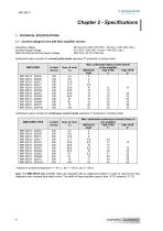
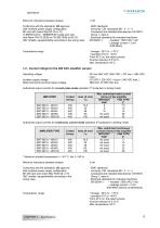
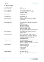
Specifications: The document outlines the specifications for the SMT-BD1/t amplifier series, detailing the rated voltage (400 Vrms) and maximum authorized current for various models. The amplifiers operate within a temperature range of 5°C to 40°C, with a maximum ambient temperature of 50°C. The PWM switching frequency is set at 8 kHz, and the current loop bandwidth exceeds 1 kHz. The amplifiers conform to CE and EMC standards, with specific immunity and disturbance standards listed.
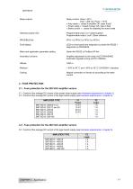
Procedures: The document provides detailed procedures for fuse protection for both 220 VAC and 400 VAC amplifier versions, specifying the types and ratings of fuses required for different amplifier models. It also includes instructions for connecting the amplifiers, detailing the location and function of various connectors and LEDs.
Standards and Recommendations: The amplifiers comply with CE approval and EMC standards, including immunity standards CEI 801-2-3-4 and conducted and radiated disturbances EN 55011. Electrical standards for industrial machines are also met, specifically EN 60204.1. Recommendations for wiring and grounding are provided to ensure compliance with these standards.
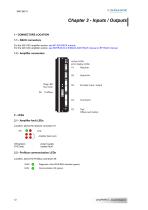
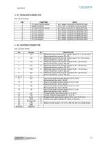
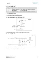
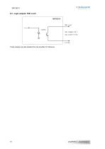
Inputs/Outputs: The document describes the inputs and outputs for the SMT-BD1/t amplifiers, including connectors for resolver, encoder, control, PROFIBUS, RS-232, and test connections. It specifies the pin configurations and functions for each connector, as well as the logic input and output specifications.
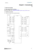
Connections: Connection diagrams are provided for power supply, motor connections, and amplifier I/O connections. The document emphasizes the importance of proper grounding and shielding to maintain compliance with EMC requirements. Specific instructions are given for motor and resolver cables, as well as serial link cables, to ensure effective shielding and grounding.
Shield Connection Recommendations: Command cables such as resolver, serial link, and Profibus, along with power lines, must be connected and disconnected with the amplifier turned off.
Chapter 5 – Adjustable Functions: All hardware adjustments for the SMT-BD1/t amplifier module are detailed in diagrams. Key components include current loops, serial link RS422, firmware memory, power fuse, and logic fuse. Specific adjustments are required for different amplifier ratings, especially for versions with 70 A and 100 A current ratings.
Resolver Transformation Ratio Adjustment: Adjustments are necessary for resolvers with transformation ratios other than 0.5, using the "P-RES" components.
Braking System Selection: Braking resistor selection is available on "w" referenced amplifiers, with specific jumper settings for different models.
Chapter 6 – Commissioning: Commissioning steps include speed control loop adjustment, motor adjustment, amplifier configuration, Profibus communication, and amplifier programming. Installation of PC software involves connecting the serial RS232 link between PC and amplifier. The BPCW software operates with Windows® 3.11/95/98/2000.
1. Amplifier Hardware Configuration: Standard configuration includes resolver adjustment, motor thermal probe settings, and current loops adjustment.
Motor Thermal Sensor Configuration: Settings differ for PTC and NTC thermal sensors, with specific jumper configurations and threshold adjustments.
Current Loops Adjustments: Adjustments vary based on amplifier version (400 VAC or 220 VAC) and motor specifications. Calculations for G factor determine jumper settings.
2. Putting into Operation: Ensure auxiliary supply voltage is applied before power supply voltage. Test both auxiliary and power supply voltages for compliance with rated values.
3. Motor Adjustment: Motor parameters can be set via BPCW software or Profibus. Adjustments include current limitation settings and speed parameters.
4. Speed Control Loop Adjustment: Auto-tuning procedure identifies motor and load specifications, calculating regulator gain parameters. Adjustments ensure proper motor operation and stability.
Enabling and Brake Control: Enabling can be done via Profibus or BPCW software. The amplifier includes a brake control signal, which is low powered and requires additional control mechanisms.
Brake Control: The BMM 05 AF single-axis rack includes a power relay for brake control, unlike other racks. Brake control is linked to the amplifier status, with parameters for adjusting brake delay when active or inactive.
Jog Control: Jog control allows continuous motor operation in either direction, activated via Profibus control. Parameters include jog speed, acceleration, and deceleration times.
Unwinder/Rewinder Configuration: This section covers rotation direction, gearing ratio adjustment, diameter sensor calibration, encoder ratio calibration, tension measurement calibration, PID loop adjustment for tension control, and parameter settings for tension control. Key formulas and procedures are provided for each aspect.
Profibus Address: Each amplifier is identified by a unique address, which can be modified via RS-232 link or a Profibus class 2 master device.
Parameters Saving: After adjustments, parameters must be saved in the EEPROM with the amplifier disabled.
Operation Mode Selection: The amplifier can operate in Profibus or standalone mode, selectable via a configuration switch.
Programming: SMT-BD1/t amplifiers support up to 64 pre-programmed sequences for various control types. Sequences can be linked for complex applications, with programmable logic inputs and outputs for control.
Control Sequence Parameters: The document outlines various control sequence parameters essential for programming and managing motor operations. These include type, tension, stretching, holding, speed, acceleration/deceleration, gearing ratio, and torque.
Sequence Set Point Selection: Different set point sources can be selected for control sequences like Tension, Speed 1, Speed 2, and Torque. Options include internal set points, analog set points, and master encoder gearing.
Variable Diameter Operation: This section discusses the adaptation of gearing ratios and torque set points based on spool diameter changes. Methods include constant ratio, diameter sensor modulation, and line encoder modulation. The document emphasizes the importance of accurate gearing ratio calculations for effective tension control.
Servo Loop Gains Adaptation: The document describes the adaptation of speed servo loop gains to maintain stability as spool diameter changes. This involves continuous adjustment of proportional and integral speed regulator gains.
Edition of a Control Sequence: Details on editing control sequences, particularly tension control sequences, are provided. Parameters include tension set point, stretching time, holding time, speed set point, and gearing ratio gain. The document also explains error handling and sequence transitions.
Gearing Ratio Adaptation Procedure: The procedure involves stopping and locking the material at the roller level, running the spool driving motor at a constant rewind speed, and measuring motor displacement to calculate the gearing ratio gain. Errors occur if the master encoder displacement exceeds 10% of the reference value or if a timeout occurs.
Speed 1 Control Sequence: This sequence allows for creating a desired speed profile using internal speed set points. Parameters include acceleration, running, and deceleration times, with a speed set point value of 200 rpm. The sequence can be linked to others for continuous operation.
Speed 2 Control Sequence: Similar to Speed 1, this sequence uses an analog speed reference for unwinder/rewinder applications. It ensures constant material line speed by adjusting motor speed based on spool diameter changes.
Torque Control Sequence: This sequence involves accelerating the motor to a speed set point and holding torque at a specified value. It includes safety features to stop the sequence if overspeed occurs. The sequence is used for tension control in winding/unwinding applications.
Sequences Chaining: Sequences can be linked using parameters like "Next sequence," "Counter," and "Jump." Conditional jumps are controlled by logic inputs, allowing for flexible sequence execution based on input status.
Logic Inputs and Outputs: Logic inputs can trigger sequence start or stop conditions, while logic outputs can be manipulated to reflect sequence status. Both inputs and outputs are integrated into the sequence control system.
Triggering Outputs: The document outlines various methods for triggering outputs during a control sequence, including speed, torque, and tension sequences. Outputs can be triggered at the beginning, when a reference is reached, or at the end of a sequence.
Profibus Communication: Profibus is a master-slave communication system where the INFRANOR® amplifier acts as a slave. Key parameters include the amplifier address, communication speed, and configuration, which are set in the PLC (master). The amplifier automatically detects communication speeds ranging from 9.6 KB to 12 MB. Configuration options include PPO1, PPO2, PPO3, or PPO4, defined in a GSD file.
PPO Messages: PPO messages are used for communication, consisting of PKW (parameter setting data) and PZD (process data). The master sends messages via PPO-write and receives them via PPO-read. Consistency is required, meaning all words in a message must be transferred in one go.
Configuration: PPO types are automatically provided by the GSD file or can be manually defined. Each type has specific configurations for PKW and PZD modules.
Parameter Setting (PKW): The PKW area allows reading or modifying parameters. Instructions include reading a parameter, modifying a parameter (word or double word), and the slave provides replies with status codes.
Global Control: Profibus DP global control mechanisms include SYNC, UNSYNC, FREEZE, and UNFREEZE, used for synchronizing outputs and inputs across modules and slaves.
Control via Profibus: The unwinder/rewinder is controlled via Profibus using PZD data. Control words and input commands are sent from master to slave, while status and feedback are sent from slave to master.
Operation Diagram: The document includes an operation diagram describing the amplifier control process, detailing stages from "ENABLE inhibited" to "Operation enabled."
Overview: This document provides detailed technical specifications and operational procedures for controlling motors using Profibus in an industrial setting. It includes sections on motor control functions, enabling/disabling procedures, sequence execution, and parameter settings.
1. Motor Control Functions: OFF Functions: OFF1, OFF2, and OFF3 are used to disable the motor with varying priorities and deceleration rates. OFF3 provides maximum deceleration. Error Handling: Errors and OFF commands are effective at all levels, requiring status checks for execution.
2. Unwind/Rewind Mode: When enabled, allows sequence execution, jogging, and motor stopping with programmed or maximum deceleration. Sequence execution is acknowledged by specific control word bits.
3. Driving the Unwinder/Rewinder: Enabling/Disabling: Involves sending specific control words from PLC to the unwinder/rewinder. Disabling is achieved by deactivating OFF bits. Sequence Starting: Initiated by entering a sequence number and toggling a control word bit. All-Speed Control: Allows control of the amplifier in various speed modes using specific parameters.
4. Parameter Setting by Profibus: Parameter List: Includes motor parameters, current parameters, speed regulator parameters, and application parameters. Motor Parameters: Define motor pole pairs, phase order, and resolver shift. Auto-phasing procedure calculates these automatically. Current Parameters: Set maximum and rated current limits, and I2t protection mode. Speed Regulator Parameters: Include proportional, integral gains, and current control filters. Auto-tuning adjusts these based on motor and load characteristics. Application Parameters: Define amplifier modes and maximum motor speed.
5. Key Procedures: Auto-Phasing: Automatically calculates motor parameters with the motor disabled and uncoupled. Cogging Torque Compensation: Acquires and compensates for motor cogging torque, necessary for high torque accuracy applications.
6. Notes: Parameters are saved in EEPROM, and specific instructions are required for writing and saving. Ensure safety by checking for free motor shaft rotation before executing procedures.
Motor Speed and Direction Parameters: Motor speed can be adjusted between 100 rpm and 14000 rpm with the amplifier disabled. The motor rotation direction can be reversed using PNU 722, with 0 for normal and 1 for reversed direction, also with the amplifier disabled.
Acceleration and Speed Error Parameters: The acceleration ramp (PNU 723) defines the time for acceleration or deceleration to maximum speed, limited to 1-16000 ms, and is applicable only in speed mode. The speed following error (PNU 724) sets the limit for speed error, ranging from 0 to 14000 rpm, with the amplifier disabled.
Brake Control Parameters: Brake delay active (PNU 726) and inactive (PNU 727) define the timing for brake release and inhibition, respectively, both limited to 0-16000 ms. Manual brake control (PNU 728) enables or disables the brake, with 0 disabling and 1 activating it.
EEPROM and Offset Compensation: Saving in the EEPROM (PNU 729) stores amplifier parameters, excluding sequence parameters, with the amplifier disabled. Offset compensation (PNU 880) adjusts the analog input 1 offset, requiring a 0-volt setting before execution.
Unwinder/Rewinder Parameters: Amplifier configuration (PNU 742) selects input signals for tension, speed, torque, and diameter, with execution requiring a disabled amplifier. Software versions for unwinder/rewinder (PNU 770) and Profibus (PNU 771) are read in hexadecimal.
Error Codes and Position Parameters: Amplifier error codes (PNU 773) are detailed across three bytes, indicating various errors. Motor position (PNU 774) and resolver value (PNU 775) provide positional data.
Encoder Output Parameters: Encoder output resolution (PNU 750) is limited by application speed, with specific resolutions for different speed ranges. Encoder output programming (PNU 754) and enabling (PNU 755) manage encoder output settings.
Manual Jog Parameters: Speed in jog (PNU 763) is defined as a percentage of maximum motor speed, with acceleration (PNU 764) and deceleration (PNU 765) ramps limited to 1-16000 ms.
PID Loop Parameters: Scaling gain (PNU 830), proportional gain (PNU 831), integral gain (PNU 832), and derivative gain (PNU 833) define the PID loop for tension or speed control, with specific conversion and limitation values.
Gearing Ratio Calibration: Parameters like diameter low-pass filter (PNU 840) and sensor values (PNU 841-843) calibrate the gearing ratio, with specific voltage and ratio settings.
Tension Control Parameters: Tension measurement low-pass filter (PNU 860) and tension error tolerance (PNU 862) manage tension control, with overspeed (PNU 863) and undertension limits (PNU 864) detecting faults and errors.
Technical Document Summary:
1. Tension Control Parameters: The document outlines parameters for controlling tension in a system. Key parameters include Ratio Init Sequence and Sequence Error Link (PNU: 865).
2. Torque Control Parameters: Parameters for torque control include Overtorque Factor (PNU: 870), Diameter Ratio Range (PNU: 871), and Overspeed Limit (PNU: 863).
3. Sequence Reading/Writing: Sequences are defined by parameters (PNU 782 to PNU 811) and stored in EEPROM. Key instructions include Reading a Sequence (PNU: 780) and Writing a Sequence (PNU: 781).
4. Troubleshooting: Diagnostic methods include LED displays, serial link, and Profibus link. Faults are categorized and prioritized for troubleshooting.
Troubleshooting Guide:
1. Faults and Solutions:
1.1 Cogging Torque Fault: Occurs if cogging torque compensation is enabled without proper acquisition procedure.
1.2 Motor Temperature Fault: Check jumper configuration and connections if fault occurs during commissioning.
1.3 Amplifier Temperature Fault: Ensure correct fan type is used for amplifiers with specific current ratings.
1.4 Power Stage Fault: Check DC bus and transformer secondary voltages during startup.
1.5 Resolver Fault: Check resolver connections and component values.
1.6 RDC Fault: Verify component values and ensure motor speed does not exceed limits.
1.7 I2T Fault: Check rated current values against authorized currents in pulse mode.
1.8 Position Fault: Adjust Speed following error parameter if necessary.
2. Operating Problems:
2.1 Motor Issues: Ensure amplifier and power supply are on, check fuses and connections.
2.2 Noise and Oscillations: Check resolver wiring and mechanical mounting.
3. Service and Maintenance: When replacing an amplifier, ensure hardware configuration matches and transfer EEPROM parameters.
4. Appendix:
4.1 Logic Inputs: Inputs can be configured in positive or negative logic.
4.2 AMP. READY and POWER READY Outputs: Outputs are affected by amplifier faults and power supply configurations.
4.3 Speed Following Error Protection: Adjust threshold parameter to detect uncontrolled movements.
4.4 I2T Protection: Describes current limitation in Fusing and Limiting modes with calculation formulas.
4.5 Master/Slave Configuration: Details on configuring amplifiers for master/slave operations.
4.6 Cogging Torque Compensation: Procedure for compensating cogging torque.
Cogging Torque in Brushless Permanent Magnet Motors: Cogging torque arises from the interaction between rotor magnets and stator slots due to the reluctance difference between the copper windings and the iron stator teeth. It can be evaluated manually when the amplifier is disabled. The SMT-BD1/t amplifier offers cogging torque compensation for applications requiring torque accuracy greater than 1%.
Cogging Torque Compensation Setup Procedure: Begin amplifier commissioning and adjustment as per chapter 6. Uncouple the motor from the load to prevent external disturbances during cogging torque acquisition. If selected, disable the Reduced stiffness at standstill command, then perform an Auto-tuning procedure with High bandwidth and Standard filter selection. Execute the Cogging torque acquisition procedure, which takes a few minutes as the motor moves slowly over 1 or 2 revolutions in both directions. The cogging torque value is stored in the amplifier EEPROM upon completion. Switch off the amplifier, couple the motor to the load, switch on the amplifier again, enable the Cogging compensation command, and execute the Save parameters to EEPROM procedure.
Amplifier Types and Specifications: Amplifier current ratings range from 4 A to 100 A (220 VAC) or 15 A to 100 A (400 VAC). Braking system available for 220 VAC amplifiers (single-axis rack). Additional heatsink option for 220 VAC amplifiers (total width = 18 TE). Serial link options: RS 232 or RS 422. Amplifier voltage ratings: 220 VAC or 400 VAC.
Cautions: The motor shaft must remain undisturbed during the cogging torque acquisition procedure. If the motor, resolver, amplifier, or EEPROM memory is changed, the cogging torque acquisition procedure must be repeated.




 XtrapulsPac_EN
 SMTBSi-2Tz_en_2.1
 PacSimBox_d_1
 Pac-SF01_flyer_en_18.02
 Pac_User_1.2.1.218
 Pac_Templates_en_1.9
 Pac_STO_Installation_en_2.2
 Pac_SF01_operating_en_1.6
 Pac_SF01_EN
 Pac_Installation_en_2.23
 Pac_flyer_en_17.12
 Option_CT_EMF
 MOVINOR_LH055_LH086_LH097_LH142
 ma_series
 GemSafeTorqueOff_en_1.1
 CD1pm_e_1.2(old)
 CD1pInst_e_7.2(old)
 CD1kInst_e_4.1(old)
 CD1k_CANopenProtocol_e_1.3(old)
 CD1a_e_7.1(old)
 Catalogue gamme SMT-BD1
 BM20A(F)v3_0
 BM20A(D)v3_0
 BF400(GB)v2_2
 BF400(D)v2_2
 BF230(GB)v2_0
 BF230(F)v2_0
 BD2m_e_2.2
 BD2m(GB)2.0
 BD2_e_3.2
 BD2(GB)3.1
 BD2(D)3.1
 Movinor_LH_e
 ma_series
 BD1t(F)3.0
 BD1pInst(GB)3.0
 BD1pInst(F)3.0
 BD1pInst(D)3.0
 BD1pCD1pUse_e_2.4
 BD1m(GB)5.0
 BD1m(F)5.0
 BD1m(D)v3_3
 BD1k(GB)2.1
 BD1k(F)2.1
 BD1j(GB)v2_41
 BD1j(F)v2_4
 BD1i(GB)v2_21
 BD1i(F)v2_2
 BD1h(F)3.0
 BD1h(D)3.0
 BD1g(GB)v3_0
 BD1g(F)v3_0
 BD1a400(GB)v2_3
 BD1a400(F)v2_3
 BD1a400(D)v2_3
 BD1(GB)7.1_noPW
 BD1(GB)7.1
 BD1(F)7.1_noPW
 BD1(F)7.1
 BD1(D)7.1
 BD1 Katalog
 Easy_User_5.0.1.60.2
 01ma_smv_e_01953
 PacHP-SF_Flyer_en_23.06
 IRD_User_Manual_en_1.2.XX.54.rev_b
 PacHP_User_en_1.2.8.100.b
 PacHP_SF02_operating_en_1.6
 PacHP_SF01_operating_en_2.0
 PacHP_Installation_en_2.9
 PacHP_Series_Brochure
 PacHP_Flyer_us_20.10
 IRD_Installation_en_1.5
 Easy_STO_en_1.4
 Easy_DB_STO_en_1.2
 Easy_DB_Installation_en_1.4
 CD1pmUser_en_4.2
 CD1pmInst_en_8.15
 CD1k_CANopenProtocol_en_2.10.1.1
 CD1pm_ProfibusProtocol_en_1.5
 CD1kUser_en_2.3
 CD1a_en_8.17
 CD1kInst_en_5.16
 CD1_STO_en_1.8
 CD1_flyer_en_14.09
 Braking_Resistors_en_1.5
 XtracontrolDC2_EN
 Flyer_VisiTouchCNC_EN_V1.1-1
 XtraforsWashdown_EN-2024
 DataSheet_CybIO_CNC_V1.0
 XtraforsPrime_EN-2024
 XtraforsMSS_EN
 XtraforsMSA_EN_2024
 XtraforsEx_EN-2024
 XtraforsBR_EN-2024
 XtraforsBL_EN-2024
 XtraforsBC-ed01-vs3
 Manual_XtraforsPrime
 Drawing_1
 Datasheet_MSS
 Datasheet_2
 Datasheet_1
 BLSBLT_series
 BL220221
 BL270
BL270 BL190
BL190 bl100_series
 bl40_series
 BL30
BL30 2019-01_XtraforsFP-DSL_FR
 Movinor_T_EN
 Movinor_N_EN
 Movinor_Low_Voltage_EN
 Manual Movinor T 03-2026
 Manual Movinor N 03-2026
 XtrapulsEasy™ AC servo-drive
 XtrapulsCD1 AC servo-drives
 CybIO
CybIO AC SERVOMOTORS
 Movinor® N AC Servomotors





 AN_CD1ak_AbsoluteEncoder_en_2.0
 AN_CD1ak_SinCosTracks_e_1.0
 AN_CD1pm_AbsoluteEncoder_en_2.0
 AN_CD1pm_SinCosTracks_e_1.0
 AN_DC_bus_interfacing_en_1.3
 CD1_EC_conformity_24.05
 CD1_STO_conformity_19.02
 EtherCAT Interface_en_1.3
 Easy_EC_Conformity_24_10
 GDPS_EC_conformity_24.07
 IRD_EC_Conformity_25.03
 PacHP_TÜV_certificate_25.07
 BD1c(F)v2_01
 BD1c(GB)v2_01
 BD1d(F)v2_01
 BD1d(GB)v2_01
 BD1e(F)v2_01
 BD1f(F)v2_01
 BD1f(GB)v2_01
 Pac_EC_conformity_25.04



















