
- Catalogs
- Infranor Group
- BD1pInst(D)3.0


BD1pInst(D)3.0

BD1pInst(D)3.0
This section underscores the critical importance of adhering to safety guidelines when operating electrical machines in industrial settings. It highlights the risks associated with exposed live parts and moving components, emphasizing that only qualified personnel should handle these devices. The necessity of following operating instructions and maintaining proper documentation is also stressed.
The SMT-BD1/p series controllers are designed for controlling current, speed, and position of brushless AC motors. They are compatible with 220 VAC and 400 VAC power supplies and can be configured for single and multi-axis racks. The controllers include their own power supply and feature IGBT transistors and DSP for digital signal processing.
This section details the technical specifications for the 220 VAC and 400 VAC controller versions, including operating voltage, auxiliary voltage, and output currents. It specifies the maximum allowable currents for different fan types and the conditions under which these currents apply.
The document lists the EMC standards that the controllers comply with, such as EN 55011 and CEI 801, ensuring electromagnetic compatibility and immunity. It also mentions the CE marking and relevant electrical standards for industrial machinery, like EN 60204-1.
Guidelines for proper installation and wiring are provided, including grounding and shielding instructions to prevent electrostatic discharge and ensure safety. The importance of using anti-static measures when handling the devices is emphasized.
References to additional necessary documents for commissioning the controllers are included, such as rack configurations and application manuals for the PROFIBUS positioning system.
- Temperature Range: Storage: -20°C to +70°C; Operation: +5°C to +40°C. Above 40°C, nominal currents must be reduced by 3% per °C. Maximum temperature is 50°C.
- Voltage and Current Ratings: Operating voltage for DC-Bus is 565 VDC (range: 480 VDC to 685 VDC max). Auxiliary voltage is 310 VDC (range: 200 VDC to 340 VDC). Motor output voltage between phases is 380 Veff for DC-Bus 565 VDC.
- Output Currents: Pulse current mode and continuous current mode are specified for different controller types with varying maximum allowable nominal currents.
- Inductance: Minimum inductance between phases is 2 mH.
- Compliance: CE approval with multi-axis power supply configuration and network filter. EMC standards include immunity (CEI standards 801-2-3-4) and conducted/radiated disturbances (EN 55011, Group 1, Class A).
- PWM Switching Frequency: 10 KHz.
- Speed and Position Control: Adjustable speed control bandwidth and maximum motor speed settings. Encoder position output with programmable resolution and accuracy considerations.
- Analog Outputs: Various outputs for speed and current monitoring with specified voltage ranges and resolutions.
- Logic Inputs and Outputs: Includes enable, end switches, index, and error reset functions. Relay outputs for controller and power readiness.
- Communication Interfaces: Profibus and RS232 interfaces for diagnostics and parameterization.
- 220 VAC Version: Specific fuses for power and logic control.
- 400 VAC Version: Logic control fuses specified.
- Connector Pin Assignments: Detailed pin assignments for various connectors including resolver, encoder, control, Profibus, RS-232, and test connectors.
- Shielding and Grounding: Emphasizes the importance of proper shielding and grounding to meet EMC standards.
- Ensure auxiliary voltage is applied before power voltage. Check voltage levels and ensure no undervoltage errors are present.
- Details on hardware settings for the controller, including resolver transformation ratio adjustments and serial interface configurations.
The document provides detailed specifications for the SMT-BD1/p installation, focusing on the RS-422 interface and ballast systems for various power ranges (220/04w to 220/60w). It specifies the configuration of braking resistors and the selection bridges for different power levels.
The configuration of motor temperature sensors is outlined, distinguishing between PTC and NTC types. For PTC sensors, the MN bridge is closed, and the OP bridge is open, with specific resistance settings provided. For NTC sensors, the OP bridge is closed, and the MN bridge is open, with similar resistance settings.
Settings for current control circuits are detailed for both 400 VAC and 220 VAC controllers. The document provides specific configurations for different motor models and current ratings, using positions B1, B2, and B3 based on calculated values of G, which depend on the controller current and phase inductance.
The logic inputs (FC+, FC-, ENABLE, INDEX) can be configured for positive or negative logic. The document explains the configuration of these inputs and the conditions under which the "Controller Ready" and "Power Ready" outputs are activated or deactivated.
An example is provided for ordering the SMT-BD1/p, detailing the controller current sizes, braking systems, additional cooling options, and serial interface types (RS 232 or RS 422).
Catalog excerpts
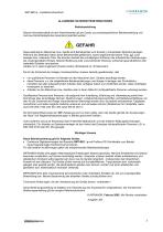
SMT-BD1/p - Installationshandbuch ALLGEMEINE SICHERHEITSINFORMATIONEN Betriebsanleitung Dieses Informationsblatt mit den Warnhinweisen gilt als Zusatz zur produktspezifischen Betriebsanleitung und muß aus Sicherheitsgründen besonders beachtet werden. Diese elektrischen Maschinen bzw. Geräte sind Betriebsmittel zum Einsatz in industriellen Starkstromanlagen. Während des Betriebes haben diese Betriebsmittel gefährliche, spannungsführende blanke Teile, ggf. auch bewegte bzw. rotierende Teile. Sie könnten deshalb bei unzulässigem Entfernen der erforderlichen Abdeckungen, bei unsachgemäßem Einsatz,...
Open the catalog to page 3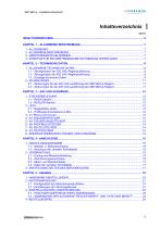
Inhaltsverzeichnis SEITE
Open the catalog to page 5
Kapitel 1 – Allgemeine Beschreibung 1 – ALLGEMEINES Die Regler der SMT-BD1/p-Baureihe sind für den Strom-, Drehzahl- und Positionsbetrieb von bürstenlosen ACMotoren mit Transmitter-Resolver und sinusförmiger Ausgangsspannung konzipiert. Der SMT-BD1/p-Servoregler wird sowohl mit 220 VAC-Netzeinspeisung als auch 400 VAC-Netzeinspeisung betrieben. Der Einschubregler mit 220 VAC-Einspeisung ist sowohl in Kompaktausführung als auch zum Betrieb in einem mehrachsigen 19"-Rack von maximal 6 Achsen mit integriertem Netzteil verfügbar. Der Einschubregler mit 400 VAC-Einspeisung ist nur zum Betrieb in einem...
Open the catalog to page 7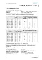
CINFRANOR SERVO DRIVES & MOTION CONTROL Betriebsspannung DC-Bus 310 VDC (270 VDC < DC-Bus < 340 VDC max.) Motor-Ausgangsspannung zwischen Phasen 200 Veff fur DC-Bus 310 VDC Ausgangsstrome in Impulsstrom-Betriebsart (,,Sperre"-Betriebsart der I2t-Sicherheitsfunktion) Mindestinduktivitat zwischen Phasen Normgerechtheit: CE-Zulassung mit mehrachsiger Netzteil-Konfiguration BF-Rack mit Netzfilter BF-35 bzw. 70 oder SMTB.M 20 A-BMM05F/05AF-Einachsrack mit Netzfiltern FN 612-20/06, FN 356-16/06 bzw. BF-35. "360°-Abschirmungen; Aquipotential gemaft Anschluftanweisungen. - Geleitete und gestrahlte Storungen:...
Open the catalog to page 8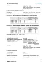
f SERVO DRIVES & MOTION CONTROL Ab 40°C sind die Nennstrome um 3 %/°C zu reduzieren. Maximale Temperatur: 50°C. Betriebsspannung DC-Bus 565 VDC (480 VDC < DC-Bus < 685 VDC max.) Motor-Ausgangsspannung zwischen Phasen 380 Veff fur DC-Bus 565 VDC Ausgangsstrome in Impulsstrom-Betriebsart (,,Sperre"-Betriebsart der I2t-Sicherheitsfunktion) Maximale Raumtemperatur = + 40°C, Luftertyp 2 = 90 l/s. Mindestinduktivitat zwischen Phasen Normgerechtheit: CE-Zulassung mit mehrachsiger Netzteil-Konfiguration BF/400-Rack und Netzfilter F400-35 bzw. 70. "360°-Abschirmungen; Aquipotential gemaG AnschluGanweisungen....
Open the catalog to page 9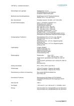
Abtastperiode = 0,5 ms Anti-Sättigungssystem des Integrators Einstellbare Digitalverstärkungen Schaltfrequenz für 45°-Phasenverschiebung: Wählbar: 50 Hz, 75 Hz oder 100 Hz Einstellbar zwischen 100 U/Min. und 10 000 U/Min. Zwei A- u. B-Kanäle in Quadratur mit n Nullimpuls(en) pro Umdrehung. Programmierbare Auflösung: Max. 8192 Imp./U. bis zu 900 U/M Max. 4096 Imp./U. bis zu 3600 U/M Max. 1024 Imp./U. bis zu 10000 U/M Genauigkeit: 8 Bogenminuten + 1/4 Imp. (2 Bogenminuten + 1/4 Imp. optionell) Bemerkung: Die gesamte Positionsgenauigkeit muß die Genauigkeit des verwendeten Resolvers berücksichtigen....
Open the catalog to page 10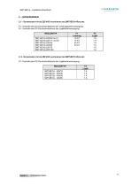
F1 : Kontrolle des DC-Durchschnittstroms der Leistungskartenversorgung F2 : Kontrolle des DC-Durchschnittstroms der Logikkartenversorgung Kapitel 2 - Technische Daten
Open the catalog to page 11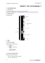
Kapitel 3 – Ein- und Ausgänge 1 – STECKERBELEGUNG 1.1 – RACK-STECKER Für die 400 VAC-Reglerversion, s. Bedienungsanleitung BF/400-RACK. Für die 220 VAC-Reglerversion, s. Bedienungsanleitungen BF-RACK sowie SMTB.M20A-EINACHSRACK. 1.2 – REGLER-STECKER Frontplattenstecker LEDs ON/SYS Errors 2 – LEDs 2.1 – REGLERFEHLER-LEDS Stelle: über den X1-Resolverstecker SYS codierte Fehler ON (grün): Versorgung SYS: Systemfehler 2.2 – PROFIBUSKOMMUNIKATIONS-LEDS Stelle: über den X6-Profibus-Stecker
Open the catalog to page 12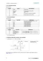
1 - Logikeingange: FC+, FC-, INDEX und ENABLE Diese Eingange konnen mittels Brucken sowohl in positiver als auch in negativer Logik konfiguriert werden (s. Kapitel 5, Abs. 3.1)
Open the catalog to page 14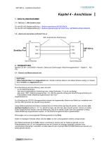
Kapitel 4 - Anschlüsse 1 - ANSCHLUSSDIAGRAMME 1.1 – NETZTEIL- U. MOTORANSCHLÜSSE Für die 400 VAC-Reglerausführung, s. Bedienungsanleitung BF/400-RACK. Für die 220 VAC-Reglerausführung, s. Bedienungsanleitungen BF-RACK bzw. SMTBM20A-EINACHSRACK. 1.2 – ANSCHLUSS DER SERIELLEN SCHNITTSTELLE 360°-Anschluß der Abschirmung 2 - VERDRAHTUNG (gemäß CEI 801- und EN55011-Normen. Siehe auch Zeichnungen "Abschirmungsanschluß" – Kapitel 4, 2.2). 2.1 – ERDUNG UND MASSEVERDRAHTUNG ACHTUNG ! Jedes leitende Kabel muß abgeschirmt sein. Werden mehrere Kabel in der selben Schiene verlegt, so müssen diese verdrillt...
Open the catalog to page 15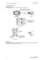
SMT-BD1/p - Installationshandbuch 2.2 – ABSCHIRMUNGSANSCHLÜSSE ALLGEMEINE REGEL Die Abschirmung darf über die gesamte Kabellänge nicht unterbrochen werden. Selbsthaftendes Kupferband, falls notwendig, zur Erweiterung des Abschirmungdurchmessers für eine optimale Befestigung unter der Klemmschelle Metallstecker für Resolver u. Motor Der Metallklemmenkasten erlaubt das Löten des Kabels auf der Abschirmung. Diese Lösung entspricht nicht genau den EMK-Bedingungen, ist aber zulässig Metall- bzw. metallisierter SUB-D-Kunststoffstecker So kurz wie möglich Erde U V W SMT.AS / M.AS SMT-BM 20 A Die Befestigungsschrauben...
Open the catalog to page 16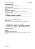
SMT-BD1/p - Installationshandbuch 2.3 – MOTOR- UND RESOLVERKABEL Motore und Resolver werden über ihr Gehäuse geerdet. Kabeleingänge müssen vorzugsweise über Metallstecker mit Ringen zur Gewährleistung des "360°"Abschirmungsanschlusses erfolgen. Das Resolverkabel muß paarweise verdrillt und abgeschirmt sein (sin, cos, ref.). Motorkabel müssen ebenfalls abgeschirmt sein. 2.4 – KABEL DER SERIELLEN SCHNITTSTELLE Das Kabel der seriellen Schnittstelle muß ebenfalls den oben beschriebenen Abschirmungsanweisungen entsprechend abgeschirmt werden. ACHTUNG ! Die Steuerkabel (Resolver, serielle Schnittstelle,...
Open the catalog to page 17All Infranor Group catalogs and technical brochures
 XtrapulsPac_EN
4 Pages
 SMTBSi-2Tz_en_2.1
43 Pages
 PacSimBox_d_1
1 Page
 Pac-SF01_flyer_en_18.02
4 Pages
 Pac_User_1.2.1.218
253 Pages
 Pac_Templates_en_1.9
27 Pages
 Pac_STO_Installation_en_2.2
13 Pages
 Pac_SF01_operating_en_1.6
63 Pages
 Pac_SF01_EN
4 Pages
 Pac_Installation_en_2.23
82 Pages
 Pac_flyer_en_17.12
4 Pages
 Option_CT_EMF
6 Pages
 MOVINOR_LH055_LH086_LH097_LH142
23 Pages
 ma_series
6 Pages
 GemSafeTorqueOff_en_1.1
12 Pages
 CD1pm_e_1.2(old)
18 Pages
 CD1pInst_e_7.2(old)
35 Pages
 CD1kInst_e_4.1(old)
40 Pages
 CD1k_CANopenProtocol_e_1.3(old)
86 Pages
 CD1a_e_7.1(old)
45 Pages
 Catalogue gamme SMT-BD1
11 Pages
 BM20A(F)v3_0
20 Pages
 BM20A(D)v3_0
20 Pages
 BF400(GB)v2_2
21 Pages
 BF400(D)v2_2
21 Pages
 BF230(GB)v2_0
23 Pages
 BF230(F)v2_0
23 Pages
 BD2m_e_2.2
69 Pages
 BD2m(GB)2.0
70 Pages
 BD2_e_3.2
53 Pages
 BD2(GB)3.1
53 Pages
 BD2(D)3.1
54 Pages
 Movinor_LH_e
4 Pages
 ma_series
6 Pages
 BD1t(GB)3.1
81 Pages
 BD1t(F)3.0
85 Pages
 BD1pInst(GB)3.0
25 Pages
 BD1pInst(F)3.0
23 Pages
 BD1pCD1pUse_e_2.4
57 Pages
 BD1m(GB)5.0
58 Pages
 BD1m(F)5.0
57 Pages
 BD1m(D)v3_3
64 Pages
 BD1k(GB)2.1
35 Pages
 BD1k(F)2.1
36 Pages
 BD1j(GB)v2_41
19 Pages
 BD1j(F)v2_4
21 Pages
 BD1i(GB)v2_21
23 Pages
 BD1i(F)v2_2
27 Pages
 BD1h(F)3.0
65 Pages
 BD1h(D)3.0
59 Pages
 BD1g(GB)v3_0
28 Pages
 BD1g(F)v3_0
28 Pages
 BD1a400(GB)v2_3
43 Pages
 BD1a400(F)v2_3
44 Pages
 BD1a400(D)v2_3
45 Pages
 BD1(GB)7.1_noPW
45 Pages
 BD1(GB)7.1
45 Pages
 BD1(F)7.1_noPW
47 Pages
 BD1(F)7.1
47 Pages
 BD1(D)7.1
45 Pages
 BD1 Katalog
11 Pages
 Easy_User_5.0.1.60.2
190 Pages
 01ma_smv_e_01953
40 Pages
 PacHP-SF_Flyer_en_23.06
4 Pages
 IRD_User_Manual_en_1.2.XX.54.rev_b
216 Pages
 PacHP_User_en_1.2.8.100.b
280 Pages
 PacHP_SF02_operating_en_1.6
103 Pages
 PacHP_SF01_operating_en_2.0
63 Pages
 PacHP_Installation_en_2.9
91 Pages
 PacHP_Series_Brochure
8 Pages
 PacHP_Flyer_us_20.10
4 Pages
 IRD_Installation_en_1.5
42 Pages
 Easy_STO_en_1.4
14 Pages
 Easy_DB_STO_en_1.2
14 Pages
 Easy_DB_Installation_en_1.4
36 Pages
 CD1pmUser_en_4.2
55 Pages
 CD1pmInst_en_8.15
40 Pages
 CD1k_CANopenProtocol_en_2.10.1.1
108 Pages
 CD1pm_ProfibusProtocol_en_1.5
50 Pages
 CD1kUser_en_2.3
26 Pages
 CD1a_en_8.17
62 Pages
 CD1kInst_en_5.16
46 Pages
 CD1_STO_en_1.8
16 Pages
 CD1_flyer_en_14.09
4 Pages
 Braking_Resistors_en_1.5
10 Pages
 XtracontrolDC2_EN
4 Pages
 Flyer_VisiTouchCNC_EN_V1.1-1
2 Pages
 XtraforsWashdown_EN-2024
2 Pages
 DataSheet_CybIO_CNC_V1.0
6 Pages
 XtraforsPrime_EN-2024
2 Pages
 XtraforsMSS_EN
4 Pages
 XtraforsMSA_EN_2024
2 Pages
 XtraforsEx_EN-2024
2 Pages
 XtraforsBR_EN-2024
2 Pages
 XtraforsBL_EN-2024
2 Pages
 XtraforsBC-ed01-vs3
4 Pages
 Manual_XtraforsPrime
46 Pages
 Drawing_1
1 Page
 Datasheet_MSS
5 Pages
 Datasheet_2
2 Pages
 Datasheet_1
4 Pages
 BLSBLT_series
2 Pages
 BL220221
2 Pages
 BL270
BL2702 Pages
 BL190
BL1902 Pages
 bl100_series
6 Pages
 bl40_series
6 Pages
 BL30
BL302 Pages
 2019-01_XtraforsFP-DSL_FR
4 Pages
 Movinor_T_EN
4 Pages
 Movinor_N_EN
4 Pages
 Movinor_Low_Voltage_EN
4 Pages
 Manual Movinor T 03-2026
46 Pages
 Manual Movinor N 03-2026
63 Pages
 XtrapulsEasy™ AC servo-drive
4 Pages
 XtrapulsCD1 AC servo-drives
4 Pages
 CybIO
CybIO6 Pages
 AC SERVOMOTORS
2 Pages
 Movinor® N AC Servomotors
4 Pages






Archived catalogs
 AN_CD1ak_AbsoluteEncoder_en_2.0
10 Pages
 AN_CD1ak_SinCosTracks_e_1.0
7 Pages
 AN_CD1pm_AbsoluteEncoder_en_2.0
10 Pages
 AN_CD1pm_SinCosTracks_e_1.0
7 Pages
 AN_DC_bus_interfacing_en_1.3
5 Pages
 CD1_EC_conformity_24.05
1 Page
 CD1_STO_conformity_19.02
2 Pages
 EtherCAT Interface_en_1.3
20 Pages
 Easy_EC_Conformity_24_10
1 Page
 GDPS_EC_conformity_24.07
1 Page
 IRD_EC_Conformity_25.03
1 Page
 PacHP_TÜV_certificate_25.07
2 Pages
 BD1c(F)v2_01
19 Pages
 BD1c(GB)v2_01
19 Pages
 BD1d(F)v2_01
25 Pages
 BD1d(GB)v2_01
25 Pages
 BD1e(F)v2_01
22 Pages
 BD1f(F)v2_01
17 Pages
 BD1f(GB)v2_01
18 Pages
 Pac_EC_conformity_25.04
1 Page




















