
- Catalogs
- Infranor Group
- BD1pCD1pUse_e_2.4


BD1pCD1pUse_e_2.4

BD1pCD1pUse_e_2.4
Catalog excerpts
OINFRANOR SERVO DRIVES & MOTION CONTROL
Open the catalog to page 1
! This is a general manual describing a series of servo amplifiers having output capability suitable for driving AC brushless sinusoidal servo motors. This manual may be used in conjunction with appropriate and referenced drawings pertaining to the various specific models. Instructions for storage, use after storage, commissioning as well as all technical details require the MANDATORY reading of the manual before getting the amplifiers operational. Maintenance procedures should be attempted only by highly skilled technicians having good knowledge of electronics and servo systems with variable...
Open the catalog to page 3
Windows® is a registered trade-mark of MICROSOFT® CORPORATION. STEP7® is a registered trade-mark of SIEMENS®.
Open the catalog to page 4
5E*VO DRIVES It MOTION CONIXOL
Open the catalog to page 5
SBP/O DRIVES S MOTION CONTROl
Open the catalog to page 6
OINFRANOR 5E*VO DRIVES & MOTION CON1VOI Chapter 1 - General description |1 - INTRODUCTION INFRANOR® Profibus positioners are digital PWM servo amplifiers that provide motion servo control for AC sinusoidal motors (brushless) with transmitter resolver. - the plug-in SMT-BD1/p series is available as a single-axis block version or as a multi-axis version that can receive up to six axes in a standard 19" rack. Both versions are including a power supply unit. - the CD1-p series is a small-sized and low current single-axis version. Both SMT-BD1/p and CD1-p are operating with a PROFIBUS-DP interface;...
Open the catalog to page 7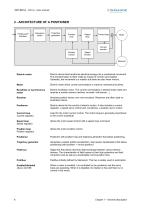
Profibus-DP interface Sequence switch Trajectory generator Position loop Speed loop Current loop Current monitor Position monitor Speed monitor Resolver Electric motor Electric device that transforms electrical energy into a mechanical movement. This transformation is often made by means of current commutation. Generally, the movement is a rotation but there are also linear motors. Electric motor which current commutation is made by mechanical brushes. Brushless or synchronous motor Electric brushless motor. The current commutation is electronically made and requires a position sensor (resolver,...
Open the catalog to page 8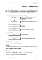
Chapter 2 - Commissioning | A WARNING During the machine adjustments, some drive connection or parameter setting errors may involve dangerous axis movements. It is the user's responsibility to take all necessary steps in order to reduce the risk due to uncontrolled axis movements during the operator's presence in the concerned area. The various stages of a first positioner commissioning are described below: Definition of the resolution. Limit switches. Following error. Current regulator adjustment. Definition of the current limitations and of the I2t protection. Adjustment of the motor control...
Open the catalog to page 9
1 - CHECKING THE POSITIONER HARDWARE CONFIGURATION The positioner standard configuration for MAVILOR motors equipped with a TAMAGAWA resolver is the following: SMT-BD1/p positioner: • Resolver adjustment card P RES: 4 x 12,7 KΩ 1%. • Current loops adjustment. • Motor thermal probe PTC: Jumper MN. • Positive control logic: Jumpers E. F. G closed. • No auxiliary supply: Jumper JK closed and jumper KL open. • SW1 "OFF" on all switches. CD1-p positioner: • Resolver P RES adjustment board: 4 x 12,7 KΩ 1%. For the positioner adjustment to other resolver types, or to another control logic, see Installation...
Open the catalog to page 10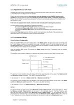
3.3 - Adjustment to a new motor Uncouple the motor from the mechanical load and check that the motor shaft is free and for free rotation (1 revolution) that is not dangerous for the operator. Execute the auto-phasing procedure (the positioner must be disabled and the ENABLE signal must be activated) in order to define the parameters Number of pole pairs, Motor phase and Resolver adjustment. Please note that during the auto-phasing procedure the motor is automatically enabled and then disabled when the procedure is over. If the motor is equipped with a brake, unlock the brake manually before starting...
Open the catalog to page 11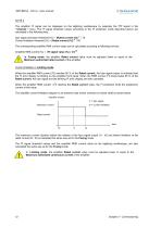
NOTE 2 The amplifier I²t signal can be displayed on the digitizing oscilloscope by selecting the "I²t" signal in the “ Channel ” menu. The I²t signal threshold values according to the I²t protection mode described above are calculated in the following way: Idyn signal activation threshold (%) = [Rated current (%)] 2 / 70 2 Current limitation threshold (%) = [Rated current (%)] / 50 The corresponding amplifier RMS current value can be calculated according to following formula : Amplifier RMS current (%) = [I²t signal value (%) x 50]1/2 In Fusing mode, the amplifier Rated current value must be...
Open the catalog to page 12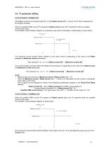
3.5 - I2t protection (CD1p) Current limitation in Fusing mode If the RMS current as not dropped below 85 % of the Rated current after 1 second, the I2t fault is released and the amplifier disabled. When the amplifier RMS current (I2t) reaches the Rated current value, the I2t protection limits the amplifier current at this value. The amplifier current limitation diagram in an extreme case (motor overloaded or shaft locked) is shown below: Amplifier current Maximum current t2 = current limitation t3 = I2t fault Rated current The maximum current duration before limitation at the rated current is...
Open the catalog to page 13
3.6 - Rotation/counting direction This possibility defines the position counting direction with regard to the motor rotation direction. For the encoder position output, the counting direction remains unchanged with regard to the motor rotation direction. On Mavilor motors, in normal rotation, the position is incrementing in the motor CW rotation direction. In reverse rotation, the position is incrementing in the motor CCW rotation direction. 3.7 - Maximum application speed The parameter Max. speed defines the maximum speed with which the positioner can control the motor. This parameter must be:...
Open the catalog to page 14
In the case of an axis with unbalanced load (constant torque due to a vertical load), proceed as follows: Select the current "Limiting" mode. Initialize the speed loop gains corresponding to the unloaded motor (run the auto-tuning procedure with the motor uncoupled from its mechanical load). Couple the motor with the load. If possible, make a speed control; otherwise, close the position loop with a stable gain. A Move the shaft by means of the speed input command until a maintaining position where one motor revolution is not dangerous for operator and machine (far enough from the mechanical limit...
Open the catalog to page 15All Infranor Group catalogs and technical brochures
 XtrapulsPac_EN
4 Pages
 SMTBSi-2Tz_en_2.1
43 Pages
 PacSimBox_d_1
1 Page
 Pac-SF01_flyer_en_18.02
4 Pages
 Pac_User_1.2.1.218
253 Pages
 Pac_Templates_en_1.9
27 Pages
 Pac_STO_Installation_en_2.2
13 Pages
 Pac_SF01_operating_en_1.6
63 Pages
 Pac_SF01_EN
4 Pages
 Pac_Installation_en_2.23
82 Pages
 Pac_flyer_en_17.12
4 Pages
 Option_CT_EMF
6 Pages
 MOVINOR_LH055_LH086_LH097_LH142
23 Pages
 ma_series
6 Pages
 GemSafeTorqueOff_en_1.1
12 Pages
 CD1pm_e_1.2(old)
18 Pages
 CD1pInst_e_7.2(old)
35 Pages
 CD1kInst_e_4.1(old)
40 Pages
 CD1k_CANopenProtocol_e_1.3(old)
86 Pages
 CD1a_e_7.1(old)
45 Pages
 Catalogue gamme SMT-BD1
11 Pages
 BM20A(F)v3_0
20 Pages
 BM20A(D)v3_0
20 Pages
 BF400(GB)v2_2
21 Pages
 BF400(D)v2_2
21 Pages
 BF230(GB)v2_0
23 Pages
 BF230(F)v2_0
23 Pages
 BD2m_e_2.2
69 Pages
 BD2m(GB)2.0
70 Pages
 BD2_e_3.2
53 Pages
 BD2(GB)3.1
53 Pages
 BD2(D)3.1
54 Pages
 Movinor_LH_e
4 Pages
 ma_series
6 Pages
 BD1t(GB)3.1
81 Pages
 BD1t(F)3.0
85 Pages
 BD1pInst(GB)3.0
25 Pages
 BD1pInst(F)3.0
23 Pages
 BD1pInst(D)3.0
24 Pages
 BD1m(GB)5.0
58 Pages
 BD1m(F)5.0
57 Pages
 BD1m(D)v3_3
64 Pages
 BD1k(GB)2.1
35 Pages
 BD1k(F)2.1
36 Pages
 BD1j(GB)v2_41
19 Pages
 BD1j(F)v2_4
21 Pages
 BD1i(GB)v2_21
23 Pages
 BD1i(F)v2_2
27 Pages
 BD1h(F)3.0
65 Pages
 BD1h(D)3.0
59 Pages
 BD1g(GB)v3_0
28 Pages
 BD1g(F)v3_0
28 Pages
 BD1a400(GB)v2_3
43 Pages
 BD1a400(F)v2_3
44 Pages
 BD1a400(D)v2_3
45 Pages
 BD1(GB)7.1_noPW
45 Pages
 BD1(GB)7.1
45 Pages
 BD1(F)7.1_noPW
47 Pages
 BD1(F)7.1
47 Pages
 BD1(D)7.1
45 Pages
 BD1 Katalog
11 Pages
 Easy_User_5.0.1.60.2
190 Pages
 01ma_smv_e_01953
40 Pages
 PacHP-SF_Flyer_en_23.06
4 Pages
 IRD_User_Manual_en_1.2.XX.54.rev_b
216 Pages
 PacHP_User_en_1.2.8.100.b
280 Pages
 PacHP_SF02_operating_en_1.6
103 Pages
 PacHP_SF01_operating_en_2.0
63 Pages
 PacHP_Installation_en_2.9
91 Pages
 PacHP_Series_Brochure
8 Pages
 PacHP_Flyer_us_20.10
4 Pages
 IRD_Installation_en_1.5
42 Pages
 Easy_STO_en_1.4
14 Pages
 Easy_DB_STO_en_1.2
14 Pages
 Easy_DB_Installation_en_1.4
36 Pages
 CD1pmUser_en_4.2
55 Pages
 CD1pmInst_en_8.15
40 Pages
 CD1k_CANopenProtocol_en_2.10.1.1
108 Pages
 CD1pm_ProfibusProtocol_en_1.5
50 Pages
 CD1kUser_en_2.3
26 Pages
 CD1a_en_8.17
62 Pages
 CD1kInst_en_5.16
46 Pages
 CD1_STO_en_1.8
16 Pages
 CD1_flyer_en_14.09
4 Pages
 Braking_Resistors_en_1.5
10 Pages
 XtracontrolDC2_EN
4 Pages
 Flyer_VisiTouchCNC_EN_V1.1-1
2 Pages
 XtraforsWashdown_EN-2024
2 Pages
 DataSheet_CybIO_CNC_V1.0
6 Pages
 XtraforsPrime_EN-2024
2 Pages
 XtraforsMSS_EN
4 Pages
 XtraforsMSA_EN_2024
2 Pages
 XtraforsEx_EN-2024
2 Pages
 XtraforsBR_EN-2024
2 Pages
 XtraforsBL_EN-2024
2 Pages
 XtraforsBC-ed01-vs3
4 Pages
 Manual_XtraforsPrime
46 Pages
 Drawing_1
1 Page
 Datasheet_MSS
5 Pages
 Datasheet_2
2 Pages
 Datasheet_1
4 Pages
 BLSBLT_series
2 Pages
 BL220221
2 Pages
 BL270
BL2702 Pages
 BL190
BL1902 Pages
 bl100_series
6 Pages
 bl40_series
6 Pages
 BL30
BL302 Pages
 2019-01_XtraforsFP-DSL_FR
4 Pages
 Movinor_T_EN
4 Pages
 Movinor_N_EN
4 Pages
 Movinor_Low_Voltage_EN
4 Pages
 Manual Movinor T 03-2026
46 Pages
 Manual Movinor N 03-2026
63 Pages
 XtrapulsEasy™ AC servo-drive
4 Pages
 XtrapulsCD1 AC servo-drives
4 Pages
 CybIO
CybIO6 Pages
 AC SERVOMOTORS
2 Pages
 Movinor® N AC Servomotors
4 Pages






Archived catalogs
 AN_CD1ak_AbsoluteEncoder_en_2.0
10 Pages
 AN_CD1ak_SinCosTracks_e_1.0
7 Pages
 AN_CD1pm_AbsoluteEncoder_en_2.0
10 Pages
 AN_CD1pm_SinCosTracks_e_1.0
7 Pages
 AN_DC_bus_interfacing_en_1.3
5 Pages
 CD1_EC_conformity_24.05
1 Page
 CD1_STO_conformity_19.02
2 Pages
 EtherCAT Interface_en_1.3
20 Pages
 Easy_EC_Conformity_24_10
1 Page
 GDPS_EC_conformity_24.07
1 Page
 IRD_EC_Conformity_25.03
1 Page
 PacHP_TÜV_certificate_25.07
2 Pages
 BD1c(F)v2_01
19 Pages
 BD1c(GB)v2_01
19 Pages
 BD1d(F)v2_01
25 Pages
 BD1d(GB)v2_01
25 Pages
 BD1e(F)v2_01
22 Pages
 BD1f(F)v2_01
17 Pages
 BD1f(GB)v2_01
18 Pages
 Pac_EC_conformity_25.04
1 Page




















