
- Catalogs
- Infranor Group
- BD1m(D)v3_3


BD1m(D)v3_3

BD1m(D)v3_3
The document provides detailed procedures for configuring and operating a motor control system, focusing on manual control, auto-tuning, and encoder output parameter settings. Key parameters include encoder resolution and zero pulse settings, which are crucial for motor rotation and positioning accuracy.
Encoder Output Parameters
Encoder resolution affects the equivalent resolution on channels A and B during motor rotation, with limitations based on motor speed. Adjustable parameters include the number of zero pulses, zero pulse origin shift, and zero pulse width.
Input/Output Configuration
The configuration menu allows for setting the polarity of opto-coupled inputs and outputs, which can be used for sequence selection and pulse outputs with adjustable durations.
Position Resolution Parameters
This section defines position resolution parameters per motor rotation, including decimal places and units, as well as following error thresholds and dead band settings for position control.
General Parameters
General parameters cover speed profiles, brake delay settings, and analog input limitations for programmed speed reduction, affecting overall motor operation.
Manual Operation Parameters
Parameters for manual movement include movement speed, acceleration, and deceleration times, essential for operations via JOG inputs or serial interface.
Parameter Storage and File Management
Parameters must be saved in non-volatile memory post-configuration, with instructions on saving, loading, and printing parameter files.
Programming and Sequence Editing
The programming section details sequence setup, editing, and execution, including functions for copying, pasting, downloading, and uploading sequences. Sequence parameters such as move type, position, speed, and output triggers are explained.
Execution and Start Conditions
This section covers start conditions for sequences and conditional transitions based on input states, emphasizing correct parameter settings for successful execution.
The document also covers the operation of the SMT-BD1/m controller, focusing on sequence initiation and oscilloscope application. Sequences can be triggered via the START logic input or through the serial interface using BD1m software. The oscilloscope's display settings, such as time base and amplitude, can be adjusted using function keys.
Error Troubleshooting
A comprehensive guide to troubleshooting system errors, stored errors, and operational disturbances is provided. Key errors include "BUSY" errors indicating autotest or autophase failures, "NovRAM" errors related to parameter storage, and various temperature and voltage-related errors, each with specific diagnostic and corrective actions.
Operational Disturbances
Common issues such as motor non-start, lack of torque, and motor noise are addressed, with solutions involving checks on power supply, parameter settings, and mechanical connections.
Service and Maintenance
Guidelines for replacing controllers include ensuring hardware configuration consistency and transferring parameter storage from the old to the new controller.
Appendix
The appendix details the configuration and application of the SMT-BD1/m controller with a display terminal, including terminal configuration, main menu functions, and sequence modification. It emphasizes the use of ASCII commands for parameter adjustments and the importance of correct software termination to maintain mode settings.
Instructions for sequence position, speed, acceleration, and braking changes are provided, with conditions for execution and examples for clarity. The document also covers sequence execution, position feedback, input and output state, absolute movement, and hardware settings.
Hardware Settings
Details on resolver connections, motor connections, logic control settings, and shielding connections are provided, emphasizing proper configuration and grounding methods.
The document includes specifications for the SMT-BD1/m controller, options for RS 232 and RS 422 connections, and various controller current sizes. It also covers updates and new features introduced with EPROM version 7.08, such as the "Ampli OK" signal, "TEACH" input, and new ASCII commands.
New Functions Configurable with BD1m 2.2 Software
New functions include "Minimum SEQ Duration," "Positioning Window," "Digital CAM," and "Software Limit Switch," each with specific operational details. The document concludes with information on reading logic inputs and reversing analog input limitations.
Catalog excerpts
de der ag am En tr h c a N ng Siehe gsanleitu r mit Bedienu le g e R gelieferte 7.08 über neu n ersio EPROM-V
Open the catalog to page 1
SMT-BD1/m ALLGEMEINE SICHERHEITSINFORMATIONEN Betriebsanleitung Dieses Informationsblatt mit den Warnhinweisen gilt als Zusatz zur produktspezifischen Betriebsanleitung und muß aus Sicherheitsgründen besonders beachtet werden. GEFAHR Diese elektrischen Maschinen bzw. Geräte sind Betriebsmittel zum Einsatz in industriellen Starkstromanlagen. Während des Betriebes haben diese Betriebsmittel gefährliche, spannungsführende blanke Teile, ggf. auch bewegte bzw. rotierende Teile. Sie könnten deshalb bei unzulässigem Entfernen der erforderlichen Abdeckungen, bei unsachgemäßem Einsatz, falscher Bedienung...
Open the catalog to page 3
Kapitel 1 - Allgemeine Beschreibung 1 - ALLGEMEINES Der SMT-BD1/m-Servopositionierer ist für den Betrieb von bürstenlosen Motoren mit Transmitter-Resolver und sinusförmiger Ausgangsspannung konzipiert. Der SMT-BD1/m-Einschubregler eignet sich sowohl als Kompaktausführung als auch zum Betrieb in einem mehrachsigen 19"-Rack von maximal 6 Achsen. Beide Ausführungen verfügen über einen integrierten Netzteil. Der SMT-BD1/m-Servoregler kann selbstständig betrieben werden oder im Anschluß an ein PLC (bzw. PC). Er erzeugt selbst die Positionierlaufbahn. Nach der Programmierung wartet der Regler auf das...
Open the catalog to page 7
Norm für die elektrische Ausrüstung von Industriemaschinen: EN 60204.1. 2.3 -"CE"-ZEICHEN Die Geräte werden seit 1995 mit "CE"-Zeichen geliefert.
Open the catalog to page 8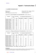
Kapitel 2 - Technische Daten |1 - ALLGEMEINE TECHNISCHE DATEN Betriebsspannung Motor-Ausgangsspannung zwischen Phasen DC-Bus 310 VDC (270 V < DC-Bus < 340 VDC) 310 VDC (200 V < Uaux < 340 VDC) Ausgangsstrome bei "Sperre"-Betriebsart der I2t-Sicherheitsfunktion (s. Kapitel 8, Absatz 3.3) * Maximale Raumtemperatur = + 40°C, Luftertyp 1 = 56 l/s, Luftertyp 2 = 90 l/s. Die SMT-BD1-X/Xr-Reglermodule sind mit einem zusatzlichen Kuhlkorper zur Erhohung der Warmeabfuhr und somit des Nennstromes ausgestattet. Die Reglerbreite mit Kuhlkorper betragt dadurch 18 TE. Kapitel 2 - Technische Daten
Open the catalog to page 9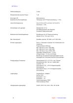
Mindestinduktivität zwischen Phasen Interne Strombegrenzung Imax: 20 % bis 100 % und Inenn: 20 % bis 50 % Imax-Dauer = 1 Sek. Abtastperiode: 0,5 ms Anti-Sättigungssystem des Integrators Einstellbare Digitalverstärkungen Schaltfrequenz für 45°-Phasenverschiebung Wählbar: 50 Hz, 75 Hz oder 100 Hz Einstellbar zwischen 100 U/Min. und 10 000 U/Min. Zwei A- u. B-Kanäle in Quadratur mit n Nullimpuls(en) pro Umdrehung Programmierbare Auflösung: Max. 8192 Imp./U. bis zu 900 U/Min. Max. 4096 Imp./U. bis zu 3600 U/Min. Max. 1024 Imp./U. bis zu 10000 U/Min. Genauigkeit: 8 Bogenminuten + 1/4 Imp. (2 Bogenminuten...
Open the catalog to page 10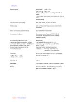
Imax = 200 mA, Pmax = 10 W "Regler bereit": geschlossen wenn Regler OK, offen bei Fehler "Leistung bereit": geschlossen wenn Leistung OK, offen bei Fehler Bremssteuerung Optogekoppelte Logikausgänge LEDs auf Frontplatte + Diagnose über serielle RS232Schnittstelle Automatische Funktionen Motoranpassung des Reglers(AUTO-PHASING) Automatische Reglereinstellung(AUTO-TUNING) Indexsuche (HOME) Normgerechtheit: CE-Zulassung mit mehrachsiger Netzteil-Konfiguration BF-Rack und Netzfilter BF 35 oder 70, bzw. SMTB.M 20 A- - Geleitete und gestrahlte Störungen: EN 55011, Einachsgehäuse und BF 35-Filter. "360°Abschirmungen;...
Open the catalog to page 11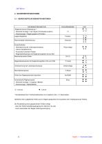
* Die Betriebsart der I2t-Sicherheitsfunktion ist in Kapitel 8, Abs. 3. 3 beschrieben. Samtliche oben aufgefuhrte Fehler sind im Regler gespeichert mit Ausnahme des "Unterspannung"-Fehlers. Die Ruckstellung eines gespeicherten Fehlers erfolgt: - uber den Fehlerruckstellungseingang (X4, Klemme 13) oder - durch ausschalten der Regler-Leistungsversorgung. Technische Daten
Open the catalog to page 12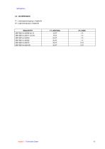
F1 : Leistungsversorgung (s. Kapitel 8) F2 : Logikversorgung (s. Kapitel 8) Kapitel 2 - Technische Daten
Open the catalog to page 13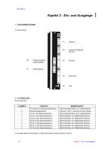
Fur sonstige Resolveranschlusse, s. ResolveranschluB-Tabelle (Kapitel 8, Abs. 2).
Open the catalog to page 14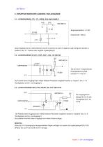
9 - SPEZIFIKATIONEN DER LOGIKEIN- UND AUSGÄNGE 9.1 - LOGIKEINGÄNGE: FC+, FC-, INDEX, RUN UND ENABLE Log + Diese Eingänge können mittels Brücken sowohl in positiver als auch in negativer Logik konfiguriert werden (s. Kapitel 8, Abs. 4.1 "Positive oder negative Logikeingänge"). 9.2 - LOGIKEINGÄNGE START, STOP, JOG+, JOG-, IN1 BIS IN8 5V SMT-BD1/m 2 2 KΩ Logikeingänge Die der Stufe 1 entsprechende Eingangsspannung liegt Die Polarität dieser Eingänge kann mittels Software-Parameter umgekehrt werden (s. Kapitel 6, Abs. 4.1.8 "Konfiguration der Ein- und Ausgänge"). 9.3 - LOGIKAUSGÄNGE SEQ, POS, SPEED,...
Open the catalog to page 18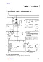
Kapitel 4 - Anschlüsse 1 - ANSCHLUSSPLÄNE 1.1 - LEISTUNGSANSCHLUSS MIT SMT-BM 20 A -EINACHSRACK ODER BF-RACK K K.1 L1 L2 L3 Erde GND N 380 Regler bereit Logikrelais Logikrelais Regler bereit ! FREIGABE Erde Regler bereit Leistung bereit *Leistung bereit: nur auf X5 verfügbar (auf Rackrückseite). Wird das "Leistung bereit"-Signal nicht benutzt, Brücke JK auf dem Regler herstellen, damit der Leistungszustand vom "Regler bereit"-Signal berücksichtigt wird. *Leistung bereit MOTOR 4 Kabel + Abschirmung RES 6 paarweise abgeschirmte Kabel (+ Temperaturfühler) (≠) : 3 A Phase- u. Sternpunkt-Schaltschütz,...
Open the catalog to page 19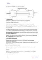
1.2 - ANSCHLUSS DER SERIELLEN SCHNITTSTELLE RS-232 Abschirmungsanschluß über 360° 2 - VERDRAHTUNG (gemäß CEI 801- u. EN55011-Normen - Siehe auch Zeichnungen in Anlage (Kapitel 8) 2.1 - ERDUNG UND ERDEVERDRAHTUNG Das Referenzpotential ist die Erde. Motoren und Resolver werden über ihr Gehäuse geerdet. Ist eine Potentialreferenz wie z.B. ein Hauptgehäuse oder ein Schrank mit niedriger Impedanz zwischen seinen verschiedenen Elementen vorhanden, so sollte diese für den Anschluß SÄMTLICHER Referenzen benutzt und selbst geerdet werden. Lange Referenzpotential-Anschlüsse dürfen nur benutzt werden, wenn...
Open the catalog to page 20All Infranor Group catalogs and technical brochures
 XtrapulsPac_EN
4 Pages
 SMTBSi-2Tz_en_2.1
43 Pages
 PacSimBox_d_1
1 Page
 Pac-SF01_flyer_en_18.02
4 Pages
 Pac_User_1.2.1.218
253 Pages
 Pac_Templates_en_1.9
27 Pages
 Pac_STO_Installation_en_2.2
13 Pages
 Pac_SF01_operating_en_1.6
63 Pages
 Pac_SF01_EN
4 Pages
 Pac_Installation_en_2.23
82 Pages
 Pac_flyer_en_17.12
4 Pages
 Option_CT_EMF
6 Pages
 MOVINOR_LH055_LH086_LH097_LH142
23 Pages
 ma_series
6 Pages
 GemSafeTorqueOff_en_1.1
12 Pages
 CD1pm_e_1.2(old)
18 Pages
 CD1pInst_e_7.2(old)
35 Pages
 CD1kInst_e_4.1(old)
40 Pages
 CD1k_CANopenProtocol_e_1.3(old)
86 Pages
 CD1a_e_7.1(old)
45 Pages
 Catalogue gamme SMT-BD1
11 Pages
 BM20A(F)v3_0
20 Pages
 BM20A(D)v3_0
20 Pages
 BF400(GB)v2_2
21 Pages
 BF400(D)v2_2
21 Pages
 BF230(GB)v2_0
23 Pages
 BF230(F)v2_0
23 Pages
 BD2m_e_2.2
69 Pages
 BD2m(GB)2.0
70 Pages
 BD2_e_3.2
53 Pages
 BD2(GB)3.1
53 Pages
 BD2(D)3.1
54 Pages
 Movinor_LH_e
4 Pages
 ma_series
6 Pages
 BD1t(GB)3.1
81 Pages
 BD1t(F)3.0
85 Pages
 BD1pInst(GB)3.0
25 Pages
 BD1pInst(F)3.0
23 Pages
 BD1pInst(D)3.0
24 Pages
 BD1pCD1pUse_e_2.4
57 Pages
 BD1m(GB)5.0
58 Pages
 BD1m(F)5.0
57 Pages
 BD1k(GB)2.1
35 Pages
 BD1k(F)2.1
36 Pages
 BD1j(GB)v2_41
19 Pages
 BD1j(F)v2_4
21 Pages
 BD1i(GB)v2_21
23 Pages
 BD1i(F)v2_2
27 Pages
 BD1h(F)3.0
65 Pages
 BD1h(D)3.0
59 Pages
 BD1g(GB)v3_0
28 Pages
 BD1g(F)v3_0
28 Pages
 BD1a400(GB)v2_3
43 Pages
 BD1a400(F)v2_3
44 Pages
 BD1a400(D)v2_3
45 Pages
 BD1(GB)7.1_noPW
45 Pages
 BD1(GB)7.1
45 Pages
 BD1(F)7.1_noPW
47 Pages
 BD1(F)7.1
47 Pages
 BD1(D)7.1
45 Pages
 BD1 Katalog
11 Pages
 Easy_User_5.0.1.60.2
190 Pages
 01ma_smv_e_01953
40 Pages
 PacHP-SF_Flyer_en_23.06
4 Pages
 IRD_User_Manual_en_1.2.XX.54.rev_b
216 Pages
 PacHP_User_en_1.2.8.100.b
280 Pages
 PacHP_SF02_operating_en_1.6
103 Pages
 PacHP_SF01_operating_en_2.0
63 Pages
 PacHP_Installation_en_2.9
91 Pages
 PacHP_Series_Brochure
8 Pages
 PacHP_Flyer_us_20.10
4 Pages
 IRD_Installation_en_1.5
42 Pages
 Easy_STO_en_1.4
14 Pages
 Easy_DB_STO_en_1.2
14 Pages
 Easy_DB_Installation_en_1.4
36 Pages
 CD1pmUser_en_4.2
55 Pages
 CD1pmInst_en_8.15
40 Pages
 CD1k_CANopenProtocol_en_2.10.1.1
108 Pages
 CD1pm_ProfibusProtocol_en_1.5
50 Pages
 CD1kUser_en_2.3
26 Pages
 CD1a_en_8.17
62 Pages
 CD1kInst_en_5.16
46 Pages
 CD1_STO_en_1.8
16 Pages
 CD1_flyer_en_14.09
4 Pages
 Braking_Resistors_en_1.5
10 Pages
 XtracontrolDC2_EN
4 Pages
 Flyer_VisiTouchCNC_EN_V1.1-1
2 Pages
 XtraforsWashdown_EN-2024
2 Pages
 DataSheet_CybIO_CNC_V1.0
6 Pages
 XtraforsPrime_EN-2024
2 Pages
 XtraforsMSS_EN
4 Pages
 XtraforsMSA_EN_2024
2 Pages
 XtraforsEx_EN-2024
2 Pages
 XtraforsBR_EN-2024
2 Pages
 XtraforsBL_EN-2024
2 Pages
 XtraforsBC-ed01-vs3
4 Pages
 Manual_XtraforsPrime
46 Pages
 Drawing_1
1 Page
 Datasheet_MSS
5 Pages
 Datasheet_2
2 Pages
 Datasheet_1
4 Pages
 BLSBLT_series
2 Pages
 BL220221
2 Pages
 BL270
BL2702 Pages
 BL190
BL1902 Pages
 bl100_series
6 Pages
 bl40_series
6 Pages
 BL30
BL302 Pages
 2019-01_XtraforsFP-DSL_FR
4 Pages
 Movinor_T_EN
4 Pages
 Movinor_N_EN
4 Pages
 Movinor_Low_Voltage_EN
4 Pages
 Manual Movinor T 03-2026
46 Pages
 Manual Movinor N 03-2026
63 Pages
 XtrapulsEasy™ AC servo-drive
4 Pages
 XtrapulsCD1 AC servo-drives
4 Pages
 CybIO
CybIO6 Pages
 AC SERVOMOTORS
2 Pages
 Movinor® N AC Servomotors
4 Pages






Archived catalogs
 AN_CD1ak_AbsoluteEncoder_en_2.0
10 Pages
 AN_CD1ak_SinCosTracks_e_1.0
7 Pages
 AN_CD1pm_AbsoluteEncoder_en_2.0
10 Pages
 AN_CD1pm_SinCosTracks_e_1.0
7 Pages
 AN_DC_bus_interfacing_en_1.3
5 Pages
 CD1_EC_conformity_24.05
1 Page
 CD1_STO_conformity_19.02
2 Pages
 EtherCAT Interface_en_1.3
20 Pages
 Easy_EC_Conformity_24_10
1 Page
 GDPS_EC_conformity_24.07
1 Page
 IRD_EC_Conformity_25.03
1 Page
 PacHP_TÜV_certificate_25.07
2 Pages
 BD1c(F)v2_01
19 Pages
 BD1c(GB)v2_01
19 Pages
 BD1d(F)v2_01
25 Pages
 BD1d(GB)v2_01
25 Pages
 BD1e(F)v2_01
22 Pages
 BD1f(F)v2_01
17 Pages
 BD1f(GB)v2_01
18 Pages
 Pac_EC_conformity_25.04
1 Page




















