
- Catalogs
- Infranor Group
- BD1j(GB)v2_41


BD1j(GB)v2_41

BD1j(GB)v2_41
Catalog excerpts
SMT-BD1/j (GB) Winding/unw. accumulator control
Open the catalog to page 1
This manual describes the option "j" of the SMT-BD1 amplifier: Accumulator control of unwind / rewind systems. The general information about the digital amplifier commissioning are described in the standard SMTBD1 manual. This manual may be used in conjunction with appropriate and referenced drawings pertaining to the various specific models. Maintenance procedures should be attempted only by highly skilled technicians (EN 60 204.1 standard) using proper test equipment. The conformity with the standards and the "CE" approval are only valid if the items are installed according to the recommendations...
Open the catalog to page 2
ACCUMULATOR CONTROL OF WINDING/UNWINDING SYSTEMS
Open the catalog to page 4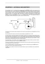
CHAPTER 1 - GENERAL DESCRIPTION The accumulator control for winding/unwinding systems requires the SMT-BD1 amplifier to be equipped with the X.X 7 EEPROM version. In this configuration, the SMT-BD1/j amplifier controls the speed of the motor driving the spool according to the material line speed and the spool diameter. The accumulator height is directly proportional to the line speed in order to allow the material storage and restitution during the spool deceleration and acceleration phases. The accumulator height measurement is received by the amplifier as an analog voltage between 0 V and +...
Open the catalog to page 6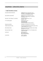
CHAPTER 2 - SPECIFICATIONS 1 - MAIN TECHNICAL DATAS Accumulator height measurement Analog input 0 V to + 10 V or 0 V to - 10 V Resolution: 11 bit as standard (15 bit optional) Low-pass filter with adjustable frequency Spool diameter measurement Analog input 0 V to + 10 V or 0 V to - 10 V Resolution: 11 bit as standard (15 bit optional) Low-pass filter: 1 Hz Spool ratio = max. diameter / min. diameter Adjustable parameter from 1 to 100 Resolution: 1/256 Sampling period: 0,5 ms Auto-tuning at setup Anti-resonance filter Automatic Gains-Spool diameter matching Speed loop bandwidth Adjustable cut-off...
Open the catalog to page 7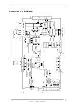
REV REW STOP CI ENABLE RESET Analog input Analog input Speed monitor Speed loop Resolver transformation Current loops Current monitor Serial interface Vector control Logic supplies Fault protections Power fault Resolver oscillator 2 - AMPLIFIER BLOCK DIAGRAM
Open the catalog to page 8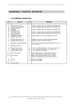
REV Rotation reversal REW Accumulator rewind Logic input 0 Volt ENABLE ENABLE 0 Volt CI current control STOP spool stop Logic input 0 Volt Amplifier fault RESET RESET input 0 Volt 17 Height measurement CV+ 16 Height measurement CV- 3 Diameter measurement DIAM 15 Analog input 0 Volt 10 Speed monitor output 2 Current monitor output 11 Analog output 0 Volt Positive or negative Positive or negative Positive or negative Positive or negative logic (see standard manual SMT-BD1) logic (see standard manual SMT-BD1) logic (see standard manual SMT-BD1) logic (see standard manual SMT-BD1) logic (see standard...
Open the catalog to page 9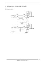
2 - SPECIFICATIONS OF THE INPUTS / OUTPUTS 2.1 - ANALOG INPUTS SMT-BD1/j Ÿ Chapter 3: Inputs - Outputs
Open the catalog to page 10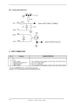
* See manual "BPCW Options", part "Digital oscilloscope". Linearity = 10 % on logic boards 01612A, 01612B and 01612C. SMT-BD1/j • Chapter 3: Inputs - Outputs
Open the catalog to page 11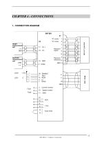
CHAPTER 4 - CONNECTIONS 1 - CONNECTION DIAGRAM X4 Height measurement cell +V GND Diameter measurement cell GND LOG+ LOGV Fault Fault Current monitor Speed monitor
Open the catalog to page 12
2 - MANDATORY WIRING It is mandatory to use a pair twitsted shielded cable s for the analog signals CV and DIAM. Cable ends must have a 360° shield connection by means of the metallic connectors at both cable ends. Otherwise, make a connection as short as possible only at the end on amplifier side with a 0 V pin of the X4 connector (see SMT-BD1 standard manual). The analog signals (CV and DIAM) must be wired according to the polarities between the sensor cells and the amplifier ( CV+ and DIAM on diff. high of the cells), and the amplifier 0 Volt MUST be connected to the cells 0 Volt by means...
Open the catalog to page 13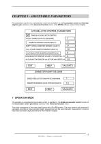
The parameters used for the unwind/rewind control are accessible via the Accumulator control and Diameter adaptive gain submenus of the Advanced functions menu, in the BPCW software version 2.54 and higher. The operation in unwind/rewind accumulator control is selected by the Enable accumulator control function of the Accumulator control parameters submenu of the Advanced functions menu. This mode corresponds to the motor speed control with a P or PI regulator. The motor speed input command is calculated according to the accumulator height measurement and the spool diameter measurement in order...
Open the catalog to page 14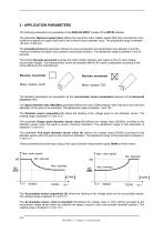
2 - APPLICATION PARAMETERS The following parameters are accessible in the ANALOG INPUT module of the BPCW software. The parameter Maximum speed (rpm) defines the maximum motor rotation speed (MS) that corresponds to the maximum material line speed value and to the minimum spool diameter value. The adjustment range is between 100 and 14 000 rpm. The Accel/Decel time (s) parameter defines the spool acceleration and deceleration time between 0 and the maximum material line speed value (positive accumulator position). The adjustment range is between 0 and 30 seconds. The function Reverse movement...
Open the catalog to page 15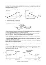
The Accumulator sensor value for max. speed (V) defines the voltage value in Volts (ASVM) provided by the accumulator height sensor at maximum material line speed is equal to zero (accumulator active position). The reading range is between 0 V and 10 V. These parameters allow the easy sizing of the accumulator height measurement signal CV as shown below. Motor speed Motor speed Max. speed ASVM Rewind if REW input active Rewind if REW input active 3 - REGULATOR PARAMETERS The speed regulator structure is shown below: KI1 S Vref Vmes The gain parameters are automatically calculated during the AUTO-TUNING...
Open the catalog to page 16
CHAPTER 6 - COMMISSIONING 1 - CHECKING THE CONFIGURATION Check the amplifier standard configuration as described in Chapter 6 of the standard SMT-BD1 manual. Check for the version of the firmware memory that must be X.X7. 2 - APPLYING POWER Turn on the amplifier as described in Chapter 6 of the standard SMT-BD1 manual. 3 - STARTING AND ADJUSTMENT Start and adjust the amplifier by means of the BPCW software,as described in Chapter 6 of the standard SMTBD1 manual. 3.1 - ADJUSTMENTS WITH EMPTY SPOOL Enter the maximum motor speed corresponding to the empty spool in the box Rated speed of the Analog...
Open the catalog to page 17All Infranor Group catalogs and technical brochures
 XtrapulsPac_EN
4 Pages
 SMTBSi-2Tz_en_2.1
43 Pages
 PacSimBox_d_1
1 Page
 Pac-SF01_flyer_en_18.02
4 Pages
 Pac_User_1.2.1.218
253 Pages
 Pac_Templates_en_1.9
27 Pages
 Pac_STO_Installation_en_2.2
13 Pages
 Pac_SF01_operating_en_1.6
63 Pages
 Pac_SF01_EN
4 Pages
 Pac_Installation_en_2.23
82 Pages
 Pac_flyer_en_17.12
4 Pages
 Option_CT_EMF
6 Pages
 MOVINOR_LH055_LH086_LH097_LH142
23 Pages
 ma_series
6 Pages
 GemSafeTorqueOff_en_1.1
12 Pages
 CD1pm_e_1.2(old)
18 Pages
 CD1pInst_e_7.2(old)
35 Pages
 CD1kInst_e_4.1(old)
40 Pages
 CD1k_CANopenProtocol_e_1.3(old)
86 Pages
 CD1a_e_7.1(old)
45 Pages
 Catalogue gamme SMT-BD1
11 Pages
 BM20A(F)v3_0
20 Pages
 BM20A(D)v3_0
20 Pages
 BF400(GB)v2_2
21 Pages
 BF400(D)v2_2
21 Pages
 BF230(GB)v2_0
23 Pages
 BF230(F)v2_0
23 Pages
 BD2m_e_2.2
69 Pages
 BD2m(GB)2.0
70 Pages
 BD2_e_3.2
53 Pages
 BD2(GB)3.1
53 Pages
 BD2(D)3.1
54 Pages
 Movinor_LH_e
4 Pages
 ma_series
6 Pages
 BD1t(GB)3.1
81 Pages
 BD1t(F)3.0
85 Pages
 BD1pInst(GB)3.0
25 Pages
 BD1pInst(F)3.0
23 Pages
 BD1pInst(D)3.0
24 Pages
 BD1pCD1pUse_e_2.4
57 Pages
 BD1m(GB)5.0
58 Pages
 BD1m(F)5.0
57 Pages
 BD1m(D)v3_3
64 Pages
 BD1k(GB)2.1
35 Pages
 BD1k(F)2.1
36 Pages
 BD1j(F)v2_4
21 Pages
 BD1i(GB)v2_21
23 Pages
 BD1i(F)v2_2
27 Pages
 BD1h(F)3.0
65 Pages
 BD1h(D)3.0
59 Pages
 BD1g(GB)v3_0
28 Pages
 BD1g(F)v3_0
28 Pages
 BD1a400(GB)v2_3
43 Pages
 BD1a400(F)v2_3
44 Pages
 BD1a400(D)v2_3
45 Pages
 BD1(GB)7.1_noPW
45 Pages
 BD1(GB)7.1
45 Pages
 BD1(F)7.1_noPW
47 Pages
 BD1(F)7.1
47 Pages
 BD1(D)7.1
45 Pages
 BD1 Katalog
11 Pages
 Easy_User_5.0.1.60.2
190 Pages
 01ma_smv_e_01953
40 Pages
 PacHP-SF_Flyer_en_23.06
4 Pages
 IRD_User_Manual_en_1.2.XX.54.rev_b
216 Pages
 PacHP_User_en_1.2.8.100.b
280 Pages
 PacHP_SF02_operating_en_1.6
103 Pages
 PacHP_SF01_operating_en_2.0
63 Pages
 PacHP_Installation_en_2.9
91 Pages
 PacHP_Series_Brochure
8 Pages
 PacHP_Flyer_us_20.10
4 Pages
 IRD_Installation_en_1.5
42 Pages
 Easy_STO_en_1.4
14 Pages
 Easy_DB_STO_en_1.2
14 Pages
 Easy_DB_Installation_en_1.4
36 Pages
 CD1pmUser_en_4.2
55 Pages
 CD1pmInst_en_8.15
40 Pages
 CD1k_CANopenProtocol_en_2.10.1.1
108 Pages
 CD1pm_ProfibusProtocol_en_1.5
50 Pages
 CD1kUser_en_2.3
26 Pages
 CD1a_en_8.17
62 Pages
 CD1kInst_en_5.16
46 Pages
 CD1_STO_en_1.8
16 Pages
 CD1_flyer_en_14.09
4 Pages
 Braking_Resistors_en_1.5
10 Pages
 XtracontrolDC2_EN
4 Pages
 Flyer_VisiTouchCNC_EN_V1.1-1
2 Pages
 XtraforsWashdown_EN-2024
2 Pages
 DataSheet_CybIO_CNC_V1.0
6 Pages
 XtraforsPrime_EN-2024
2 Pages
 XtraforsMSS_EN
4 Pages
 XtraforsMSA_EN_2024
2 Pages
 XtraforsEx_EN-2024
2 Pages
 XtraforsBR_EN-2024
2 Pages
 XtraforsBL_EN-2024
2 Pages
 XtraforsBC-ed01-vs3
4 Pages
 Manual_XtraforsPrime
46 Pages
 Drawing_1
1 Page
 Datasheet_MSS
5 Pages
 Datasheet_2
2 Pages
 Datasheet_1
4 Pages
 BLSBLT_series
2 Pages
 BL220221
2 Pages
 BL270
BL2702 Pages
 BL190
BL1902 Pages
 bl100_series
6 Pages
 bl40_series
6 Pages
 BL30
BL302 Pages
 2019-01_XtraforsFP-DSL_FR
4 Pages
 Movinor_T_EN
4 Pages
 Movinor_N_EN
4 Pages
 Movinor_Low_Voltage_EN
4 Pages
 Manual Movinor T 03-2026
46 Pages
 Manual Movinor N 03-2026
63 Pages
 XtrapulsEasy™ AC servo-drive
4 Pages
 XtrapulsCD1 AC servo-drives
4 Pages
 CybIO
CybIO6 Pages
 AC SERVOMOTORS
2 Pages
 Movinor® N AC Servomotors
4 Pages






Archived catalogs
 AN_CD1ak_AbsoluteEncoder_en_2.0
10 Pages
 AN_CD1ak_SinCosTracks_e_1.0
7 Pages
 AN_CD1pm_AbsoluteEncoder_en_2.0
10 Pages
 AN_CD1pm_SinCosTracks_e_1.0
7 Pages
 AN_DC_bus_interfacing_en_1.3
5 Pages
 CD1_EC_conformity_24.05
1 Page
 CD1_STO_conformity_19.02
2 Pages
 EtherCAT Interface_en_1.3
20 Pages
 Easy_EC_Conformity_24_10
1 Page
 GDPS_EC_conformity_24.07
1 Page
 IRD_EC_Conformity_25.03
1 Page
 PacHP_TÜV_certificate_25.07
2 Pages
 BD1c(F)v2_01
19 Pages
 BD1c(GB)v2_01
19 Pages
 BD1d(F)v2_01
25 Pages
 BD1d(GB)v2_01
25 Pages
 BD1e(F)v2_01
22 Pages
 BD1f(F)v2_01
17 Pages
 BD1f(GB)v2_01
18 Pages
 Pac_EC_conformity_25.04
1 Page




















