
- Catalogs
- Infranor Group
- BD1h(F)3.0


BD1h(F)3.0

BD1h(F)3.0
The SMT-BD1 series digital drive modules are designed for controlling brushless motors with a resolver transmitter. The SMT-BD1/h variant includes a CAN interface for receiving movement commands via the CAN bus.
The modules are CE certified, conforming to standards EN 55011 and CEI 801, and the low voltage directive as per LCIE report No 413777.
- Power Supply: 310 VDC with auxiliary options.
- Output Voltage: 200 Veff for a 310 VDC bus.
- Current Ratings: Various models with different capacities.
- PWM Frequency: 10 KHz.
- Speed Range: 100 to 14,000 RPM.
Details on connector layouts for resolver, encoder, test, command, RS-232, and CAN connectors.
Includes parameter setting and addressing for customization.
Guidelines for drive configuration, powering up, and adjusting the drive.
Describes system faults and troubleshooting steps.
Includes hardware adaptations and shielding recommendations.
Outlines specifications for a programmable device with varying points per revolution based on speed.
Includes speed and current command and measurement with specified voltage ranges.
Details various inputs and outputs including relay contacts and readiness indicators.
Features CAN bus communication and RS232 for diagnostics.
Includes AUTOPHASING, AUTOTUNING, HOME, and CI functions.
Conforms to CE standards with specific operating temperature and humidity specifications.
Describes cooling methods and safety features.
Emphasizes proper grounding, shielding, and cable types.
Each drive on the CAN network must have a unique address set using micro-switches.
Standard configuration for a MAVILOR motor with a TAMAGAWA resolver.
Check transformer secondary voltage and DC bus voltage.
Ensure CAN messages are present during adjustments.
Save parameters to EEPROM after adjustments.
Includes a brake control signal requiring a power relay.
Specific procedures for current limitation and speed regulator selection.
Addresses various system faults with diagnostic and corrective actions.
Common issues like no motor reaction and lack of torque are addressed.
- Rotation Discontinuity: Ensure proper connection of the three-phase wires.
- Noise at Rest: Check grounding connections.
- Noise During Operation: Verify mechanical transmission rigidity.
- Ensure new drive's hardware configuration matches the old one.
- Adaptations for SMT-BD1 drives are detailed in the hardware layout plan.
- Adjustments are made using bridges based on calculated G values.
- Describes current limitation modes and conditions for I2T faults.
- Logic inputs can be configured for positive or negative logic.
- Guidelines for maintaining uninterrupted shielding.
- Details the commercial designation format for the SMT-BD1 drive.
Outlines the communication protocol for CAN focusing on variable speed drives.
Periodic messages include position commands and feedback.
Facilitate parameter transfer between the CN and drives.
Lists several parameter commands such as Mode Variator and Cycle Time.
Emphasizes the importance of message configuration and timing.
1. RAM and Options: Specifies various RAM options and functionalities.
2. Software Version: Provides the software version and manufacturer identification code.
3. Drive Status: Details the status of the drive, including fault codes.
1. CAN Protocol: Outlines the CAN communication protocol.
2. Fault Masking: Allows masking of specific faults.
3. Logical I/O: Manages logical inputs and outputs.
1. Rotation Inversion: Allows inversion of motor rotation.
2. Max Speed: Sets the maximum application speed.
3. Position Measurement: Covers absolute position measurement.
1. Synchronous Motor Parameters: Defines parameters for synchronous motor control.
2. Phase Advance Coefficient: Specifies the phase advance coefficient.
1. Max and Nominal Current: Defines the maximum and nominal current limits.
2. I²t Mode: Specifies the I²t mode.
1. Proportional and Integral Gains: Defines the gains for speed and position control loops.
2. Anticipatory Term: Sets the anticipatory term to reduce lag error.
3. Acceleration Ramp: Defines the acceleration or deceleration time.
- Includes detailed conversion factors and limitations for each command.
- Emphasizes the importance of specific procedures for optimal motor performance.
1. Current Command Parameter: Influenced by the chosen bandwidth.
2. Anti-Resonance Filter: Used to activate or deactivate the filter.
3. Stability Gain Adjustment: Allows for gain adjustments to maintain loop stability.
1. Servo Activation: Activates the servo with a relay brake output delay.
2. Servo Deactivation: Deactivates the servo after a delay.
3. Fault Reset: Resets faults and cancels ongoing procedures.
4. EEPROM Backup: Saves all parameters to EEPROM.
5. Auto-Phasing: Automatically determines motor parameters.
6. Auto-Tuning: Identifies motor and load characteristics.
7. Index Search Procedure: Initiates an index search.
8. Encoder Output Programming: Programs the pseudo encoder output.
9. Manual Brake Relay Control: Activates or deactivates the brake relay.
10. Notch Torque Identification: Identifies motor notch torque.
11. Reset to Default Parameters: Resets all parameters to default values.
1. Synchronous Messages: Identifiers for synchronization and command messages.
2. Asynchronous Messages: Identifiers for request and response messages.
Catalog excerpts
SERVO DRIVES & MOTION CONTROL
Open the catalog to page 1
REMARQUE IMPORTANTE Cette notice technique concerne une série de variateurs destinés à l'asservissement des moteurs AC synchrones sinus. Celle-ci doit être utilisée en coordination avec les schémas référencés et adéquats aux différents modèles. L'accès à ce matériel ainsi que son utilisation doivent être strictement réservés au personnel qualifié : norme EN 60204-1. La conformité aux normes et à l'homologation CE n'est valable que si les appareils sont installés conformément aux recommandations des notices concernant les racks et les variateurs. Le non respect des recommandations et schémas de...
Open the catalog to page 3
Sommaire général PAGE
Open the catalog to page 5
CINFRANOR SEXVO DRIVES & MOTION CON7KX
Open the catalog to page 6
CINFRANOR PREMIERE PARTIE VARIATEUR PREMIERE PARTIE - VARIATEUR
Open the catalog to page 7
CINFRANOR PREMIERE PARTIE - VARIATEUR
Open the catalog to page 8
Sommaire première partie PAGE PREMIERE PARTIE - VARIATEUR - Somm
Open the catalog to page 9
PREMIERE PARTIE - VARIATEUR - Sommaire
Open the catalog to page 10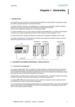
1- INTRODUCTION Les modules variateurs numériques à commande PWM sinusoïdale de la série SMT-BD1 sont destinés à piloter des moteurs sans balai équipés d'un résolveur transmetteur. Le système SMT-BD1 enfichable a une présentation bloc monoaxe ou une présentation multiaxes, étudiée de façon à pouvoir disposer d'un maximum de 6 axes dans un rack standard 19 pouces. Chacune de ces présentations dispose d'un bloc alimentation intégré. Le variateur SMT-BD1/h est une version dérivée de l'appareil standard SMT-BD1 avec interface CAN permettant de recevoir les consignes de déplacement par le bus CAN...
Open the catalog to page 11
2.2 - REFERENCE AUX NORMES APPLICABLES Les variateurs SMT-BD1 montés dans le rack BF, équipé du filtre secteur référence BF 35/70, ont été certifiés conformes aux normes de compatibilité électromagnétique : - EN 55011, groupe 1, classe A, concernant les perturbations radioélectriques, conduites et rayonnées, - CEI 801 - 2 - 3 - 4 concernant l'immunité. Les résultats dans les conditions d'essais effectués par le laboratoire extérieur du LCIE (Laboratoire Central des Industries Electriques), agréé par les instances européennes, sont consignés sous les No 416040, 416041, 416042 et 416043. Le résultat...
Open the catalog to page 12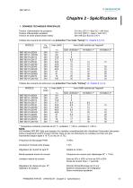
CINFRANOR SBP/O DRIVES 1 MOTION CONTROl 1 - DONNEES TECHNIQUES PRINCIPALES Tension d'alimentation de puissance Tension d'alimentation auxiliaire Tension de sortie phase-phase moteur 310 VDC (270 V < Bus DC < 340 VDC) 310 VDC (200 V < Uaux < 340 VDC) 200 Veff pour Bus DC 310 V PREMIERE PARTIE - VARIATEUR - Chapitre 2 - Specifications Tableau des courants de sortie pour une protection I2t en mode "fusing" (cf. chapitre 8, § 3.3). Frequence de decoupage PWM Inductance minimale entre phases Regulateur de courant de type PI Bande passante boucle de courant Limitation interne de courant Regulateur...
Open the catalog to page 13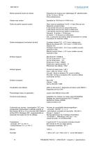
Bande passante boucle de vitesse Fréquence de coupure pour déphasage 45° sélectionnable 50 Hz, 75 Hz ou 100 Hz Filtre antirésonance Ajustable de 100 tr/min à 14 000 tr/min Sortie de position pseudo-codeur Deux voies en quadrature A et B + n tops Zéro par tour. Résolution programmable. 8 192 points max par tour jusqu'à 900 tr/min 4 096 points max par tour jusqu'à 3 600 tr/min 1 024 points max par tour jusqu'à 14 000 tr/min Précision : 8 min/arc + 1/4 de point (2 min/arc + 1/4 de point sur demande) N.B : la précision de position totale doit prendre en compte la précision du résolveur utilisé Sorties...
Open the catalog to page 14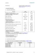
CINFRANOR Refroidissement Convection naturelle ou ventilation forcee en fonction du courant nominal (voir tableau des courants, chap. 2, § 1) PREMIERE PARTIE - VARIATEUR - Chap
Open the catalog to page 15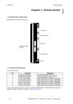
Chapitre 3 - Entrées-Sorties 1 - DISPOSITION DES CONNECTEURS Disposition des connecteurs en face avant : FONCTION TC (pin H prise capteur) Repiquage des blindages TC (pin I prise capteur) S1 (pin C prise capteur) S3 (prise D prise capteur) S4 (pin B prise capteur) S2 (pin A prise capteur) R2 (pin F prise capteur) R1 (pin E prise capteur) REMARQUE Si sonde température câblée en X1 Si pas de reprise 360° sur le connecteur Si sonde température câblée en X1 Moteur MAVILOR avec résolveur TAMAGAWA Moteur MAVILOR avec résolveur TAMAGAWA Moteur MAVILOR avec résolveur TAMAGAWA Moteur MAVILOR avec résolveur...
Open the catalog to page 16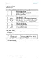
CINFRANOR 3 - X2 CONNECTEUR CODEUR Sub D 25 points femelle * : 10 V pour calibre courant variateur Linearite 10% pour carte logique de type 01612A, 01612B ou 01612C. PREMIERE PARTIE - VARIATEUR - Chapitre 3 - Entrees-Sorties
Open the catalog to page 17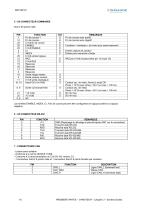
CINFRANOR 5 - X4 CONNECTEUR COMMANDE Sub D 25 points male. PREMIERE PARTIE - VARIATEUR - Chapitre 3 - Entrees-Sorties
Open the catalog to page 18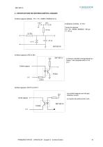
SMT-BD1/h 8 - SPECIFICATIONS DES ENTREES-SORTIES LOGIQUES Entrées logiques dédiées : FC+, FC-, INDEX, ENABLE et CI . Log + Temps de réponse : FC+, FC-, INDEX, ENABLE : 500 µs. CI : 50 µs. La tension d’entrée correspondante au niveau 1 est comprise entre 5 V et 24 V. Entrée logique Les sorties logiques sont de type collecteur ouvert. Le courant de sortie est de 5 mA. PREMIERE PARTIE - VARIATEUR - Chapitre 3
Open the catalog to page 19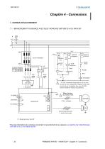
Chapitre 4 - Connexions 1 - SCHEMAS DE RACCORDEMENT 1.1 - BRANCHEMENT PUISSANCE AVEC BLOC MONOAXE SMT-BM 20 A OU RACK BF Raux AUTO-TRANSFO Arrêt puissance ENABLE (Marche) Disable (Arrêt) Marche puissance R ENABLE VAR PRET VARIATEUR * PU OK : seulement disponible sur X5 du fond de rack. Si l'on n'utilise pas le signal PU OK, faire le pont JK sur le variateur pour que Var Prêt tienne compte de l'état de la puissance. Mise à la terre du châssis rack MOTEUR 4 fils + blindage X1 6 fils blindés par paire (+ sonde thermique) (*) : Seulement pour rack BF Pour des informations plus précises concernant...
Open the catalog to page 20All Infranor Group catalogs and technical brochures
 XtrapulsPac_EN
4 Pages
 SMTBSi-2Tz_en_2.1
43 Pages
 PacSimBox_d_1
1 Page
 Pac-SF01_flyer_en_18.02
4 Pages
 Pac_User_1.2.1.218
253 Pages
 Pac_Templates_en_1.9
27 Pages
 Pac_STO_Installation_en_2.2
13 Pages
 Pac_SF01_operating_en_1.6
63 Pages
 Pac_SF01_EN
4 Pages
 Pac_Installation_en_2.23
82 Pages
 Pac_flyer_en_17.12
4 Pages
 Option_CT_EMF
6 Pages
 MOVINOR_LH055_LH086_LH097_LH142
23 Pages
 ma_series
6 Pages
 GemSafeTorqueOff_en_1.1
12 Pages
 CD1pm_e_1.2(old)
18 Pages
 CD1pInst_e_7.2(old)
35 Pages
 CD1kInst_e_4.1(old)
40 Pages
 CD1k_CANopenProtocol_e_1.3(old)
86 Pages
 CD1a_e_7.1(old)
45 Pages
 Catalogue gamme SMT-BD1
11 Pages
 BM20A(F)v3_0
20 Pages
 BM20A(D)v3_0
20 Pages
 BF400(GB)v2_2
21 Pages
 BF400(D)v2_2
21 Pages
 BF230(GB)v2_0
23 Pages
 BF230(F)v2_0
23 Pages
 BD2m_e_2.2
69 Pages
 BD2m(GB)2.0
70 Pages
 BD2_e_3.2
53 Pages
 BD2(GB)3.1
53 Pages
 BD2(D)3.1
54 Pages
 Movinor_LH_e
4 Pages
 ma_series
6 Pages
 BD1t(GB)3.1
81 Pages
 BD1t(F)3.0
85 Pages
 BD1pInst(GB)3.0
25 Pages
 BD1pInst(F)3.0
23 Pages
 BD1pInst(D)3.0
24 Pages
 BD1pCD1pUse_e_2.4
57 Pages
 BD1m(GB)5.0
58 Pages
 BD1m(F)5.0
57 Pages
 BD1m(D)v3_3
64 Pages
 BD1k(GB)2.1
35 Pages
 BD1k(F)2.1
36 Pages
 BD1j(GB)v2_41
19 Pages
 BD1j(F)v2_4
21 Pages
 BD1i(GB)v2_21
23 Pages
 BD1i(F)v2_2
27 Pages
 BD1h(D)3.0
59 Pages
 BD1g(GB)v3_0
28 Pages
 BD1g(F)v3_0
28 Pages
 BD1a400(GB)v2_3
43 Pages
 BD1a400(F)v2_3
44 Pages
 BD1a400(D)v2_3
45 Pages
 BD1(GB)7.1_noPW
45 Pages
 BD1(GB)7.1
45 Pages
 BD1(F)7.1_noPW
47 Pages
 BD1(F)7.1
47 Pages
 BD1(D)7.1
45 Pages
 BD1 Katalog
11 Pages
 Easy_User_5.0.1.60.2
190 Pages
 01ma_smv_e_01953
40 Pages
 PacHP-SF_Flyer_en_23.06
4 Pages
 IRD_User_Manual_en_1.2.XX.54.rev_b
216 Pages
 PacHP_User_en_1.2.8.100.b
280 Pages
 PacHP_SF02_operating_en_1.6
103 Pages
 PacHP_SF01_operating_en_2.0
63 Pages
 PacHP_Installation_en_2.9
91 Pages
 PacHP_Series_Brochure
8 Pages
 PacHP_Flyer_us_20.10
4 Pages
 IRD_Installation_en_1.5
42 Pages
 Easy_STO_en_1.4
14 Pages
 Easy_DB_STO_en_1.2
14 Pages
 Easy_DB_Installation_en_1.4
36 Pages
 CD1pmUser_en_4.2
55 Pages
 CD1pmInst_en_8.15
40 Pages
 CD1k_CANopenProtocol_en_2.10.1.1
108 Pages
 CD1pm_ProfibusProtocol_en_1.5
50 Pages
 CD1kUser_en_2.3
26 Pages
 CD1a_en_8.17
62 Pages
 CD1kInst_en_5.16
46 Pages
 CD1_STO_en_1.8
16 Pages
 CD1_flyer_en_14.09
4 Pages
 Braking_Resistors_en_1.5
10 Pages
 XtracontrolDC2_EN
4 Pages
 Flyer_VisiTouchCNC_EN_V1.1-1
2 Pages
 XtraforsWashdown_EN-2024
2 Pages
 DataSheet_CybIO_CNC_V1.0
6 Pages
 XtraforsPrime_EN-2024
2 Pages
 XtraforsMSS_EN
4 Pages
 XtraforsMSA_EN_2024
2 Pages
 XtraforsEx_EN-2024
2 Pages
 XtraforsBR_EN-2024
2 Pages
 XtraforsBL_EN-2024
2 Pages
 XtraforsBC-ed01-vs3
4 Pages
 Manual_XtraforsPrime
46 Pages
 Drawing_1
1 Page
 Datasheet_MSS
5 Pages
 Datasheet_2
2 Pages
 Datasheet_1
4 Pages
 BLSBLT_series
2 Pages
 BL220221
2 Pages
 BL270
BL2702 Pages
 BL190
BL1902 Pages
 bl100_series
6 Pages
 bl40_series
6 Pages
 BL30
BL302 Pages
 2019-01_XtraforsFP-DSL_FR
4 Pages
 Movinor_T_EN
4 Pages
 Movinor_N_EN
4 Pages
 Movinor_Low_Voltage_EN
4 Pages
 Manual Movinor T 03-2026
46 Pages
 Manual Movinor N 03-2026
63 Pages
 XtrapulsEasy™ AC servo-drive
4 Pages
 XtrapulsCD1 AC servo-drives
4 Pages
 CybIO
CybIO6 Pages
 AC SERVOMOTORS
2 Pages
 Movinor® N AC Servomotors
4 Pages






Archived catalogs
 AN_CD1ak_AbsoluteEncoder_en_2.0
10 Pages
 AN_CD1ak_SinCosTracks_e_1.0
7 Pages
 AN_CD1pm_AbsoluteEncoder_en_2.0
10 Pages
 AN_CD1pm_SinCosTracks_e_1.0
7 Pages
 AN_DC_bus_interfacing_en_1.3
5 Pages
 CD1_EC_conformity_24.05
1 Page
 CD1_STO_conformity_19.02
2 Pages
 EtherCAT Interface_en_1.3
20 Pages
 Easy_EC_Conformity_24_10
1 Page
 GDPS_EC_conformity_24.07
1 Page
 IRD_EC_Conformity_25.03
1 Page
 PacHP_TÜV_certificate_25.07
2 Pages
 BD1c(F)v2_01
19 Pages
 BD1c(GB)v2_01
19 Pages
 BD1d(F)v2_01
25 Pages
 BD1d(GB)v2_01
25 Pages
 BD1e(F)v2_01
22 Pages
 BD1f(F)v2_01
17 Pages
 BD1f(GB)v2_01
18 Pages
 Pac_EC_conformity_25.04
1 Page




















