- Catalogs
- Infranor Group
- BD1g(GB)v3_0


BD1g(GB)v3_0

BD1g(GB)v3_0
The SMT-BD1/g manual provides guidance on positioning servo amplifiers for AC brushless servo motors. It should be used with the SMT-BD1 manual due to shared conditions and recommendations.
The amplifier is applicable in material and drum registration, rotating cam, and conveyor registration, ensuring synchronization and compensating for slippages and interval variations.
Two modes are available: bidirectional and unidirectional registration. Product reference can be relative to the master encoder marker pulse or DM logic input, with origin acquisition options.
The amplifier supports a maximum frequency of 250 kHz for position measurement inputs, with programmable product reference pitches and encoder resolutions, offering high position repeatability and optional enhanced accuracy.
Details on pin allocation and specifications for connectors, including position, test, and control connectors, are provided.
Guidelines for control connection diagrams and wiring requirements ensure proper setup with master encoders and amplifiers.
Parameters related to operation mode, application, and position regulator settings can be adjusted for optimal performance.
Steps for configuration checking, powering the amplifier, and setting up registration applications are outlined, including origin acquisition and starting procedures.
Solutions for common issues like position following errors, registration errors, and motor noise are provided.
The control system includes a sampling period of 0.5 ms, an integrator anti-wind-up system, adjustable digital gains, and an antiresonance filter. The position loop bandwidth has an adjustable cut-off frequency for a 45° phase shift at 50, 75, or 100 Hz.
The block diagram includes components like PWM, vectorial control, resolver sensor conversion, and position loop, with connections for logic supplies and fault protections.
Stored faults can be reset using BPCW software, the fault RESET input, or by switching off the amplifier. Protection display codes are provided for position following errors.
The BPCW software module allows initialization and calculation of amplifier adjustment parameters, ensuring the minimum photocell distance is adequate.
Guidance for starting with running material and conveyor applications is provided, including adjustments for motor displacement and alignment.
Solutions for position following errors, registration errors, and operation problems are detailed, including adjustments for motor speed and alignment.
Includes hardware location diagrams and photocell wiring instructions for NPN and PNP photocells.
Catalog excerpts
SERVO DRIVES & MOTION CONTROL
Open the catalog to page 1
IMPORTANT NOTE This manual is describing a series of positioning servo amplifiers having output capability for driving AC brushless servo motors. This manual must be used in conjunction with the SMT-BD1 manual and cannot be dissociated from it. The conditions and recommendations of use as well as the responsibility and warranty restrictions mentioned in the SMT-BD1 manual are also valid for the present amplifier version SMT-BD1/g. © INFRANOR, September 2003. All rights reserved. Issue: 3.0
Open the catalog to page 3
Chapter 1 – General description 1 - INTRODUCTION Product registration applications require the SMT-I4-BD1 daughter board and the X.X5 EEPROM version on the SMT-BD1 amplifier. In this configuration, the SMT-BD1/g amplifier controls the motor shaft position with regard to the master axis position and the position of the products to be registered. The master axis position is received as two differential encoder signals A, /A and B, /B in quadrature. These signals are entered on the amplifier position connector X2. This input type allows a direct interfacing with an encoder mounted on the master...
Open the catalog to page 7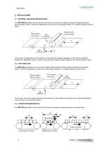
2 - APPLICATIONS 2.1 - MATERIAL AND DRUM REGISTRATION The SMT-BD1/g amplifier can be used for the control of a continuous material running with regularly spaced synchronization marks. This kind of applications can be met in the printing industry or in rotating cutting, as shown below. In this case, the registration control allows to compensate the material slippages and the interval variations between the registration marks, in order to keep the drum position always aligned on the synchronization marks. 2.2 - ROTATING CAM The SMT-BD1/g amplifier can be used for a rotating CAM application with...
Open the catalog to page 8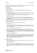
In this case, the registration control allows a regular spacing of the products with their placing in the output conveyor boxes, in spite of their irregular spacing on the input conveyor. 3 - OPERATION 3.1 - OPERATION MODES Two operation modes are available for the product registration in order to fit various kinds of applications. a) Bidirectional registration In this case, when the product to be registered has a lead over the synchronization mark, the motor can run back in order to cancel this lead. This operation mode is suited to the registration of a material equipped with regularly spaced...
Open the catalog to page 9
b) Origin acquisition with stopping on the first product After the activation of the amplifier ENABLE input, the motor follows the master axis position and stops at the detection of the first product by the RM photocell. This first product will then be registered at the next reference sensor activation (master encoder marker pulse or DM logic input). It is possible to define this way an absolute origin of the product series at the reference sensor activation. Chapter 1 – General description
Open the catalog to page 10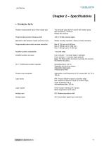
Chapter 2 – Specifications 1 - TECHNICAL DATA Position measurement input of the master axis Two encoder pulse trains A and B with marker pulse. Max. frequency = 250 kHz RS422 line receiver Programmable product reference pitch Reduction ratio between master and slave axes Master encoder resolution / Slave encoder resolution Programmable slave motor encoder resolution Amplifier position repeatability Amplifier position accuracy 8 arc minutes + 1 encoder edge in standard (2 arc minutes + 1 encoder edge optional) Note: The final position accuracy must take into account the resolver accuracy. PIV...
Open the catalog to page 11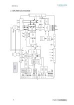
Analog output Analog inputs Position input Encoder output Position loop Speed loop Resolver sensor conversion Resolver oscillator Serial interface Current loops Current measurement Vectorial control Fault protections Power fault Logic supplies 2 - AMPLIFIER BLOCK DIAGRAM Enable ERROR
Open the catalog to page 12
CINFRANOR 3 - STORED PROTECTION The stored fault can be reset by: - the RESET function of the BPCW software, - via the fault RESET input of the X4 connector, pin 13,
Open the catalog to page 13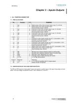
OINFRANOR SERVO DRIVES & MOTION CONTROL 1.2 - SPECIFICATION OF THE LOGIC INPUTS/OUTPUTS The RM and DM inputs are "optocoupled" inputs and operate in positive logic on the signal rising edge as shown below. The input voltage corresponds to level 1 and is between 5 V and 24 V.
Open the catalog to page 14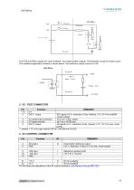
The POS and REG outputs are "open collector" and "optocoupled" outputs. The transistor is open if a fault occurs. The traditional application scheme is shown below. The maximum output current is 5 mA. SMT-BD1/g X2 pin 8 POS Imax < 5 mA PC829 Vmax < 24 V X2 pin 23 0 V POS IDC signal ±10 V, resolution: 8 bits, linearity: 2 % (10 V for amplifier current rating)* 3 CV speed input command ±10 V for ± max. speed 4 GT speed monitor ±8 V for ±14 000 rpm 5 DAC 2 output AS signal ±10 V, resolution: 8 bits, linearity: 2 %* (10 V for max. motor speed) * Linearity = 10 % for logic boards 01612A, 01612B and...
Open the catalog to page 15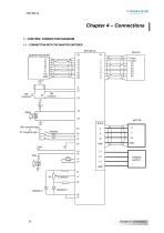
Chapter 4 – Connections 1 - CONTROL CONNECTION DIAGRAM 1.1 - CONNECTION WITH THE MASTER ENCODER SMT-BD1/g MASTER ENCODER A A/ B B/ Z Z/ +5V GND 23 0V +24V (positive logic) or 0V (negative logic) MOTOR RACK POWER SUPPLY
Open the catalog to page 16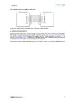
SMT-BD1/g 1.2 - CONNECTION WITH A MASTER AMPLIFIER SMT-BD1/g SLAVE An SMT-BD1 master amplifier can supply up to 10 SMT-BD1/g slave amplifiers. 2 - WIRING REQUIREMENTS For the incremental position input command signals A, B and Z of the master-slave connection, use a cable with a 360° shield connection by means of the metallic connectors at both cable ends (see Chapter 8, section 6 of the SMT-BD1 standard manual). Connect also together the 0 V of both amplifiers (pin GND of the X2 connector). The crossing of the A and B, A and A/ or B and B/ signals on the incremental position input command reverses...
Open the catalog to page 17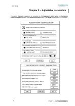
OINFRANOR SERVO DRIVES & MOTION CONTROL The specific Registration parameters are accessible via the Registration control setup and Registration control parameters submenus of the Advanced functions menu, in the BPCW software version 2.6 and higher. ENABLE REGISTRATION CONTROL “ DATUM MODE - <§> DATUM ON THE FLY o FIRST PRODUCT STOP - REFERENCE SENSOR- (§> ENCODER ZERO PULSE O DM INPUT -REFERENCE SHIFT - <§> DIGITAL SHIFT O DS ANALOG INPUT REFERENCE SHIFT VALUE (% Pitch) CANCEL HELP REGISTRATION CONTROL PARAMETERS REFERENCE PITCH (Encoder edges) PITCH CORRECTION LIMIT (Encoder edges) REGISTRATION...
Open the catalog to page 18All Infranor Group catalogs and technical brochures
 XtrapulsPac_EN
4 Pages
 XtrapulsGemTemplates_e_1.4
21 Pages
 XtrapulsGem_User_Manual_v1.2.0.64
199 Pages
 XtrapulsGem_Inst_e_2.1
42 Pages
 XtrapulsGem_Inst_e_2.0
42 Pages
 SMTBSi-2Tz_en_2.1
43 Pages
 smt-100
32 Pages
 PacSimBox_d_1
1 Page
 Pac-SF01_flyer_en_18.02
4 Pages
 Pac_User_1.2.1.218
253 Pages
 Pac_Templates_en_1.9
27 Pages
 Pac_STO_Installation_en_2.2
13 Pages
 Pac_SF01_operating_en_1.6
63 Pages
 Pac_SF01_EN
4 Pages
 Pac_Installation_en_2.23
82 Pages
 Pac_flyer_en_17.12
4 Pages
 Option_CT_EMF
6 Pages
 MOVINOR_LH055_LH086_LH097_LH142
23 Pages
 ma_series
6 Pages
 GemSafeTorqueOff_en_1.1
12 Pages
 GemProgramming_e_1.1
47 Pages
 GDPS_old_version_1.1_1
11 Pages
 CD1pm_e_1.2(old)
18 Pages
 CD1pInst_e_7.2(old)
35 Pages
 CD1kInst_e_4.1(old)
40 Pages
 CD1k_CANopenProtocol_e_1.3(old)
86 Pages
 CD1a_e_7.1(old)
45 Pages
 Catalogue gamme SMT-BD1
11 Pages
 BM20A(F)v3_0
20 Pages
 BM20A(D)v3_0
20 Pages
 BF400(GB)v2_2
21 Pages
 BF400(D)v2_2
21 Pages
 BF230(GB)v2_0
23 Pages
 BF230(F)v2_0
23 Pages
 BD2m_e_2.2
69 Pages
 BD2m(GB)2.0
70 Pages
 BD2_e_3.2
53 Pages
 BD2(GB)3.1
53 Pages
 BD2(D)3.1
54 Pages
 Movinor_LH_e
4 Pages
 ma_series
6 Pages
 BD1t(GB)3.1
81 Pages
 BD1t(F)3.0
85 Pages
 BD1pInst(GB)3.0
25 Pages
 BD1pInst(F)3.0
23 Pages
 BD1pInst(D)3.0
24 Pages
 BD1pCD1pUse_e_2.4
57 Pages
 BD1m(GB)5.0
58 Pages
 BD1m(F)5.0
57 Pages
 BD1m(D)v3_3
64 Pages
 BD1k(GB)2.1
35 Pages
 BD1k(F)2.1
36 Pages
 BD1j(GB)v2_41
19 Pages
 BD1j(F)v2_4
21 Pages
 BD1i(GB)v2_21
23 Pages
 BD1i(F)v2_2
27 Pages
 BD1h(F)3.0
65 Pages
 BD1h(D)3.0
59 Pages
 BD1g(F)v3_0
28 Pages
 BD1a400(GB)v2_3
43 Pages
 BD1a400(F)v2_3
44 Pages
 BD1a400(D)v2_3
45 Pages
 BD1(GB)7.1_noPW
45 Pages
 BD1(GB)7.1
45 Pages
 BD1(F)7.1_noPW
47 Pages
 BD1(F)7.1
47 Pages
 BD1(D)7.1
45 Pages
 BD1 Katalog
11 Pages
 08ma_ms_e_01700
20 Pages
 Easy_User_5.0.1.60.2
190 Pages
 08ma_mrm_em_01575
20 Pages
 01ma_smv_e_01953
40 Pages
 PacHP-SF_Flyer_en_23.06
4 Pages
 IRD_User_Manual_en_1.2.XX.54.rev_b
216 Pages
 PacHP_User_en_1.2.8.100.b
280 Pages
 PacHP_SF02_operating_en_1.6
103 Pages
 PacHP_SF01_operating_en_2.0
63 Pages
 PacHP_Installation_en_2.9
91 Pages
 PacHP_Series_Brochure
8 Pages
 PacHP_Flyer_us_20.10
4 Pages
 IRD_Installation_en_1.5
42 Pages
 GDPS_Installation_en_4.4
18 Pages
 Easy_STO_en_1.4
14 Pages
 Easy_DB_STO_en_1.2
14 Pages
 Easy_DB_Installation_en_1.4
36 Pages
 CD1pmUser_en_4.2
55 Pages
 CD1pmInst_en_8.15
40 Pages
 CD1k_CANopenProtocol_en_2.10.1.1
108 Pages
 CD1pm_ProfibusProtocol_en_1.5
50 Pages
 CD1kUser_en_2.3
26 Pages
 CD1a_en_8.17
62 Pages
 CD1kInst_en_5.16
46 Pages
 CD1_STO_en_1.8
16 Pages
 CD1_flyer_en_14.09
4 Pages
 Braking_Resistors_en_1.5
10 Pages
 XtracontrolDC2_EN
4 Pages
 Flyer_VisiTouchCNC_EN_V1.1-1
2 Pages
 XtraforsWashdown_EN-2024
2 Pages
 DataSheet_CybIO_CNC_V1.0
6 Pages
 XtraforsPrime_EN-2024
2 Pages
 XtraforsMSS_EN
4 Pages
 XtraforsMSA_EN_2024
2 Pages
 XtraforsEx_EN-2024
2 Pages
 XtraforsBR_EN-2024
2 Pages
 XtraforsBL_EN-2024
2 Pages
 XtraforsBC-ed01-vs3
4 Pages
 Manual_XtraforsPrime
46 Pages
 Drawing_1
1 Page
 Datasheet_MSS
5 Pages
 Datasheet_2
2 Pages
 Datasheet_1
4 Pages
 BLSBLT_series
2 Pages
 BL220221
2 Pages
 BL270
BL2702 Pages
 BL190
BL1902 Pages
 bl100_series
6 Pages
 bl40_series
6 Pages
 BL30
BL302 Pages
 2019-01_XtraforsFP-DSL_FR
4 Pages
 Movinor_T_EN
4 Pages
 Movinor_N_EN
4 Pages
 Movinor_Low_Voltage_EN
4 Pages
 Manual Movinor T 03-2026
46 Pages
 Manual Movinor N 03-2026
63 Pages
 XtrapulsEasy™ AC servo-drive
4 Pages
 XtrapulsCD1 AC servo-drives
4 Pages
 CybIO
CybIO6 Pages
 AC SERVOMOTORS
2 Pages
 Movinor® N AC Servomotors
4 Pages






Archived catalogs
 AN_CD1ak_AbsoluteEncoder_en_2.0
10 Pages
 AN_CD1ak_SinCosTracks_e_1.0
7 Pages
 AN_CD1pm_AbsoluteEncoder_en_2.0
10 Pages
 AN_CD1pm_SinCosTracks_e_1.0
7 Pages
 AN_DC_bus_interfacing_en_1.3
5 Pages
 CD1_EC_conformity_24.05
1 Page
 CD1_STO_conformity_19.02
2 Pages
 EtherCAT Interface_en_1.3
20 Pages
 Easy_EC_Conformity_24_10
1 Page
 GDPS_EC_conformity_24.07
1 Page
 IRD_EC_Conformity_25.03
1 Page
 PacHP_TÜV_certificate_25.07
2 Pages
 BD1c(F)v2_01
19 Pages
 BD1c(GB)v2_01
19 Pages
 BD1d(F)v2_01
25 Pages
 BD1d(GB)v2_01
25 Pages
 BD1e(F)v2_01
22 Pages
 BD1f(F)v2_01
17 Pages
 BD1f(GB)v2_01
18 Pages
 CE_conformity_Gem
1 Page
 Pac_EC_conformity_25.04
1 Page
 Pac_GDPS_CEconformity
1 Page
![SMT100D_e_1.01[1]](https://img.directindustry.com/pdf/repository_di/4620720/smt100d-e-101-1-1141223_1mg.jpg) SMT100D_e_1.01[1]
SMT100D_e_1.01[1]40 Pages
 STO_declaration_Gem
2 Pages