
- Catalogs
- Infranor Group
- BD1d(GB)v2_01


BD1d(GB)v2_01

BD1d(GB)v2_01
The manual details the SMT-BD1/d amplifier's master/slave electronic gearing option, requiring SMT-I1-BD1 or SMT-I2-BD1 daughter boards. It controls the slave motor's position based on the master axis's input using differential encoder signals, with a programmable reduction ratio up to 8192 ppr. Synchronization can be manual or automatic.
The slave motor receives position input via two encoder pulse trains with a maximum frequency of 250 KHz. The encoder resolution is programmable, with limits based on motor speed. The position regulator uses a PIV + Feedforward system with adjustable digital gains and an antiresonance filter. Logic inputs and outputs include JOG+ and JOG- for manual adjustments.
The X2 position connector handles encoder outputs and inputs, with specific pins for logic inputs like JOG+ and JOG-. The X3 test connector provides DAC outputs and speed input commands.
Connection diagrams for the master amplifier and encoder are provided. Mandatory wiring includes shielded cables for position input signals and proper grounding to ensure correct motor rotation direction.
Parameters for electronic gearing are accessible via the BPCW software. Key parameters include encoder resolution, following error, motor deadband, and alignment speed. These settings ensure precise control and synchronization between master and slave motors.
Commissioning involves configuration checks, powering, and adjustments. Manual and automatic alignment procedures are detailed for ensuring accurate synchronization.
Common faults include position and busy errors, with troubleshooting steps provided for issues like motor noise and oscillation.
The BPCW software provides access to all regulator parameters. Key parameters include Speed Error Low Pass Filter, Proportional Speed Gain (KP2), Integral Speed Gain (KI), Proportional Position Gain (KP1), and Feedforward Position Gain (KF). These parameters are calculated during the AUTOTUNING function.
The OFFSET button on the slave motor amplifier acquires the position reference of the master motor for automatic alignment after a voltage cutoff. This requires two SMT-BD1 amplifiers and a serial link between them. If the procedure fails, a Busy fault is displayed.
- System Stability: Ensure the master motor provides higher torque than the slave motor to prevent instability.
- Configuration Checks: Verify amplifier configuration and connections, including external encoder settings.
- Powering and Adjustment: Follow standard procedures for powering and adjusting amplifiers. Use BPCW software for commissioning and adjustments.
- Alignment Procedures: Manual and automatic alignment procedures are detailed, including the use of OFFSET and JOG inputs.
Synchronization using analogue input commands is discussed, emphasizing the need for identical parameters and configurations for both master and slave amplifiers.
Common faults such as "Position" fault are addressed with troubleshooting steps, including checking limit switches and adjusting parameters like Following Error and Maximum Speed.
- During position reference acquisition, ensure the serial link is correctly connected between X5 connectors of master and slave motors, and the master amplifier is on. If unresolved, switch off the amplifier before saving parameters to EEPROM and retry.
- In automatic alignment mode, verify the serial link between X5 connectors of master and slave amplifiers and ensure the master amplifier is on.
- Loud Crackling Noise at Standstill: Ensure Motor-Amplifier-Resolver ground connections and wiring of incremental position input command meet Chapter 4 requirements.
- Loud Noise at Standstill and Running: Check mechanical coupling rigidity. Re-execute AUTO-TUNING with lower bandwidth or activate antiresonance filter using BPCW software version 2.6 and amplifier EPROM version 5.7.
- Loud Noise When Running: Select highest position resolution on slave motor according to maximum rotation speed and adjust master motor resolution to maintain reduction ratio.
- Motor Position Oscillation at Standstill: Check mechanical coupling rigidity and increase Motor Dead band parameter in Indexer/Electronic Gearbox menu via Advanced Function.
- Location diagram of hardware options is provided in Chapter 8.
Catalog excerpts

SMT-BD1/d (GB) Master/slave electronic gearing
Open the catalog to page 1
This manual describes the option "d" of the SMT-BD1 amplifier: Master/slave electronic gearing. The general information about the digital amplifier commissioning are described in the standard SMT-BD1 manual. This manual may be used in conjunction with appropriate and referenced drawings pertaining to the various specific models. Maintenance procedures should be attempted only by highly skilled technicians (EN 60 204.1 standard) using proper test equipment. The conformity with the standards and the "CE" approval are only valid if the items are installed according to the recommendations of the...
Open the catalog to page 2
MASTER / SLAVE ELECTRONIC GEARING WITH THE SMT-BD1/d AMPLIFIER
Open the catalog to page 4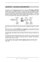
CHAPTER 1 - GENERAL DESCRIPTION The master / slave electronic gearing applications require the SMT-I1-BD1 or SMT-I2-BD1 daughter boards on the SMT-BD1 amplifier. In this configuration, the SMT-BD1/d amplifier controls the motor shaft position according to the position input command emitted by the master axis. The master axis position input command is received as two differential encoder signals: A, /A and B, /B in quadrature. These signals enter the amplifier position connector X2. This kind of input allows a direct interfacing with an encoder mounted on the master motor or on a second amplifier...
Open the catalog to page 6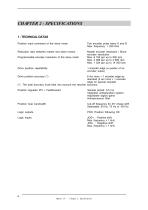
CHAPTER 2 - SPECIFICATIONS 1 - TECHNICAL DATAS Position input command of the slave motor Two encoder pulse trains A and B Max. frequency = 250 KHz Reduction ratio between master and slave motors Master encoder resolution / Slave encoder resolution Max. 8 192 ppr up to 900 rpm Max. 4 096 ppr up to 3 600 rpm Max. 1 024 ppr up to 14 000 rpm Programmable encoder resolution of the slave motor Drive position repetability 1 encoder edge (a quarter of an encoder pulse) Drive position accuracy (*) 8 Arc mins + 1 encoder edge as standard (2 arc mins + 1 encoder edge on special request) (*) The total accuracy...
Open the catalog to page 7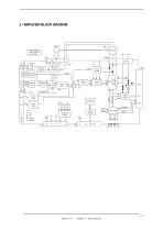
2 - AMPLIFIER BLOCK DIAGRAM Resolver MOTOR Resolver conversion Current monitor Vmes Position input Position loop Vector control Speed loop Current loops Analog input Analog input Power fault P err Vmes Vref IQ ID Imes Idc Serial interface Selectable outputs Logic supplies
Open the catalog to page 8
The stored fault can be cancelled: - by the RESET function of the BPCW software, - by the fault RESET input (pin 13 of X4), - by turning off the amplifier supply. Option "d" • Chapter 2: Specifications
Open the catalog to page 9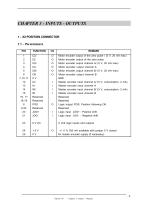
FUNCTION CZ/ CZ CA/ CA CB/ CB 0V IA/ IA IB/ IB Reserved Reserved POS Reserved JOG+ JOG- REMARK Motor encoder output of the zero pulse / (5 V, 20 mA max) Motor encoder output of the zero pulse Motor encoder output channel A/ (5 V, 20 mA max) Motor encoder output channel A Motor encoder output channel B/ (5 V, 20 mA max) Motor encoder output channel B GND Master encoder input channel A/ (5 V, consumption: 2 mA) Master encoder input channel A Master encoder input channel B/ (5 V, consumption: 2 mA) Master encoder input channel B Reserved Reserved Logic output POS: Position following OK Reserved...
Open the catalog to page 10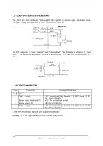
1.2 - Logic inputs/outputs specifications The JOG+ and JOG- inputs are "optocoupled" and operate in positive logic, as shown below. The input voltage corresponding to level 1 is between 5 and 24 V. The POS output is an "open collector" and "optocoupled". The transistor is inhibited if a fault occurs. The traditional application scheme is shown below. The maximum output current is 5 mA. Option "d" • Chapter 3: Inputs - Outputs See "BPCW Options" manual, part "Digital oscilloscope". Linearity: 10 % on logic boards 01612A, 01612B and 01612C.
Open the catalog to page 11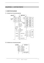
Default RESET 1.2 - Connection of the master encoder Option "d" • Chapter 4: Connections
Open the catalog to page 12
2 - MANDATORY WIRING For the incremental position input command signals A and B of the master-slave connection, use a cable with a 360° shield connection via the metal plated connectors at both cable ends (see standard manual of the SMT-BD1 digital amplifier, chapter 8, part 6) and connect the 0 Volt of both master and slave (pin GND on the X2 connector). The crossing of the A and B or A and A/ or B and B/ signals on the incremental position input command changes the rotation direction of the slave motor with regard to the master motor.
Open the catalog to page 13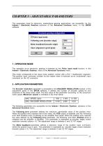
The parameters used for electronic master/slave gearing applications are accessible via the Indexer / Electronic Gearbox submenu of the Advanced functions menu, in the BPCW software. The operation as an electronic gearbox is selected by the Pulse input mode function in the Indexer / Electronic Gearbox menu of the Advanced functions menu. This mode corresponds to the slave motor position control with a PIV + feedforward regulator. The position input command emitted by the master motor is received as an incremental input command on the X2 connector. The Encoder resolution parameter is accessible...
Open the catalog to page 14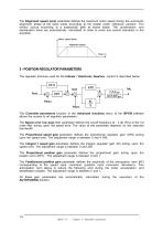
The Alignment speed (rpm) parameter defines the maximum motor speed during the automatic alignment phase of the slave motor according to the master motor reference position. The motion occurs according to a trapezoidal path as shown below. The acceleration and deceleration times are automatically calculated in order to avoid any current saturation in the amplifier. 3 - POSITION REGULATOR PARAMETERS The regulator structure used for the Indexer / Electronic Gearbox control is described below: The Controller parameters function in the Advanced functions menu of the BPCW software allows the access...
Open the catalog to page 15
4 - POSITION REFERENCE ACQUISITION The OFFSET push button of the slave motor amplifier permits the position reference acquisition of the master motor for an automatic axes alignment after a voltage cutoff. This kind of applications requires TWO SMT-BD1 amplifiers for the control of both master and slave motors as well as a serial link between the X5 connectors of both amplifiers. After the position reference acquisition of the master motor (OFFSET), the reference value is automatically stored in the amplifier EEPROM and the automatic alignment mode is activated. If the procedure has failed because...
Open the catalog to page 16All Infranor Group catalogs and technical brochures
 XtrapulsPac_EN
4 Pages
 SMTBSi-2Tz_en_2.1
43 Pages
 PacSimBox_d_1
1 Page
 Pac-SF01_flyer_en_18.02
4 Pages
 Pac_User_1.2.1.218
253 Pages
 Pac_Templates_en_1.9
27 Pages
 Pac_STO_Installation_en_2.2
13 Pages
 Pac_SF01_operating_en_1.6
63 Pages
 Pac_SF01_EN
4 Pages
 Pac_Installation_en_2.23
82 Pages
 Pac_flyer_en_17.12
4 Pages
 Option_CT_EMF
6 Pages
 MOVINOR_LH055_LH086_LH097_LH142
23 Pages
 ma_series
6 Pages
 GemSafeTorqueOff_en_1.1
12 Pages
 CD1pm_e_1.2(old)
18 Pages
 CD1pInst_e_7.2(old)
35 Pages
 CD1kInst_e_4.1(old)
40 Pages
 CD1k_CANopenProtocol_e_1.3(old)
86 Pages
 CD1a_e_7.1(old)
45 Pages
 Catalogue gamme SMT-BD1
11 Pages
 BM20A(F)v3_0
20 Pages
 BM20A(D)v3_0
20 Pages
 BF400(GB)v2_2
21 Pages
 BF400(D)v2_2
21 Pages
 BF230(GB)v2_0
23 Pages
 BF230(F)v2_0
23 Pages
 BD2m_e_2.2
69 Pages
 BD2m(GB)2.0
70 Pages
 BD2_e_3.2
53 Pages
 BD2(GB)3.1
53 Pages
 BD2(D)3.1
54 Pages
 Movinor_LH_e
4 Pages
 ma_series
6 Pages
 BD1t(GB)3.1
81 Pages
 BD1t(F)3.0
85 Pages
 BD1pInst(GB)3.0
25 Pages
 BD1pInst(F)3.0
23 Pages
 BD1pInst(D)3.0
24 Pages
 BD1pCD1pUse_e_2.4
57 Pages
 BD1m(GB)5.0
58 Pages
 BD1m(F)5.0
57 Pages
 BD1m(D)v3_3
64 Pages
 BD1k(GB)2.1
35 Pages
 BD1k(F)2.1
36 Pages
 BD1j(GB)v2_41
19 Pages
 BD1j(F)v2_4
21 Pages
 BD1i(GB)v2_21
23 Pages
 BD1i(F)v2_2
27 Pages
 BD1h(F)3.0
65 Pages
 BD1h(D)3.0
59 Pages
 BD1g(GB)v3_0
28 Pages
 BD1g(F)v3_0
28 Pages
 BD1a400(GB)v2_3
43 Pages
 BD1a400(F)v2_3
44 Pages
 BD1a400(D)v2_3
45 Pages
 BD1(GB)7.1_noPW
45 Pages
 BD1(GB)7.1
45 Pages
 BD1(F)7.1_noPW
47 Pages
 BD1(F)7.1
47 Pages
 BD1(D)7.1
45 Pages
 BD1 Katalog
11 Pages
 Easy_User_5.0.1.60.2
190 Pages
 01ma_smv_e_01953
40 Pages
 PacHP-SF_Flyer_en_23.06
4 Pages
 IRD_User_Manual_en_1.2.XX.54.rev_b
216 Pages
 PacHP_User_en_1.2.8.100.b
280 Pages
 PacHP_SF02_operating_en_1.6
103 Pages
 PacHP_SF01_operating_en_2.0
63 Pages
 PacHP_Installation_en_2.9
91 Pages
 PacHP_Series_Brochure
8 Pages
 PacHP_Flyer_us_20.10
4 Pages
 IRD_Installation_en_1.5
42 Pages
 Easy_STO_en_1.4
14 Pages
 Easy_DB_STO_en_1.2
14 Pages
 Easy_DB_Installation_en_1.4
36 Pages
 CD1pmUser_en_4.2
55 Pages
 CD1pmInst_en_8.15
40 Pages
 CD1k_CANopenProtocol_en_2.10.1.1
108 Pages
 CD1pm_ProfibusProtocol_en_1.5
50 Pages
 CD1kUser_en_2.3
26 Pages
 CD1a_en_8.17
62 Pages
 CD1kInst_en_5.16
46 Pages
 CD1_STO_en_1.8
16 Pages
 CD1_flyer_en_14.09
4 Pages
 Braking_Resistors_en_1.5
10 Pages
 XtracontrolDC2_EN
4 Pages
 Flyer_VisiTouchCNC_EN_V1.1-1
2 Pages
 XtraforsWashdown_EN-2024
2 Pages
 DataSheet_CybIO_CNC_V1.0
6 Pages
 XtraforsPrime_EN-2024
2 Pages
 XtraforsMSS_EN
4 Pages
 XtraforsMSA_EN_2024
2 Pages
 XtraforsEx_EN-2024
2 Pages
 XtraforsBR_EN-2024
2 Pages
 XtraforsBL_EN-2024
2 Pages
 XtraforsBC-ed01-vs3
4 Pages
 Manual_XtraforsPrime
46 Pages
 Drawing_1
1 Page
 Datasheet_MSS
5 Pages
 Datasheet_2
2 Pages
 Datasheet_1
4 Pages
 BLSBLT_series
2 Pages
 BL220221
2 Pages
 BL270
BL2702 Pages
 BL190
BL1902 Pages
 bl100_series
6 Pages
 bl40_series
6 Pages
 BL30
BL302 Pages
 2019-01_XtraforsFP-DSL_FR
4 Pages
 Movinor_T_EN
4 Pages
 Movinor_N_EN
4 Pages
 Movinor_Low_Voltage_EN
4 Pages
 Manual Movinor T 03-2026
46 Pages
 Manual Movinor N 03-2026
63 Pages
 XtrapulsEasy™ AC servo-drive
4 Pages
 XtrapulsCD1 AC servo-drives
4 Pages
 CybIO
CybIO6 Pages
 AC SERVOMOTORS
2 Pages
 Movinor® N AC Servomotors
4 Pages






Archived catalogs
 AN_CD1ak_AbsoluteEncoder_en_2.0
10 Pages
 AN_CD1ak_SinCosTracks_e_1.0
7 Pages
 AN_CD1pm_AbsoluteEncoder_en_2.0
10 Pages
 AN_CD1pm_SinCosTracks_e_1.0
7 Pages
 AN_DC_bus_interfacing_en_1.3
5 Pages
 CD1_EC_conformity_24.05
1 Page
 CD1_STO_conformity_19.02
2 Pages
 EtherCAT Interface_en_1.3
20 Pages
 Easy_EC_Conformity_24_10
1 Page
 GDPS_EC_conformity_24.07
1 Page
 IRD_EC_Conformity_25.03
1 Page
 PacHP_TÜV_certificate_25.07
2 Pages
 BD1c(F)v2_01
19 Pages
 BD1c(GB)v2_01
19 Pages
 BD1d(F)v2_01
25 Pages
 BD1e(F)v2_01
22 Pages
 BD1f(F)v2_01
17 Pages
 BD1f(GB)v2_01
18 Pages
 Pac_EC_conformity_25.04
1 Page




















