- Catalogs
- Infranor Group
- BD1a400(GB)v2_3


BD1a400(GB)v2_3

BD1a400(GB)v2_3
The SMT-BD1-400/I series are digital servo modules designed as PWM servo amplifiers for speed control of AC sinusoidal brushless motors with transmitter resolvers. These modules are available in a multi-axis version.
The amplifiers conform to European standards and have "CE" approval, provided they are installed according to the manual's recommendations. Proper installation and handling are emphasized to maintain compliance and safety.
The amplifiers are housed in a standard 19" rack and can accommodate up to three axes. They feature a DC/DC converter for logic voltage supply, with a direct connection to a 400 VAC mains. Key specifications include a rated DC bus voltage of 565 VDC, a maximum DC bus voltage of 685 VDC, and a motor phase-phase output voltage of 380 Vrms. The amplifiers support a PWM switching frequency of 10 KHz and have programmable resolution for encoder position output.
The amplifiers include several protection features, such as overload protection, resolver cable interruption detection, power stage failure alerts, and overtemperature warnings. Faults are displayed via LEDs on the front panel and can be reset through software or hardware means.
Details on connectors, including resolver, encoder output, test, and command connectors, are provided. Specifications for analog and logic inputs/outputs are included, such as limit switches, speed input commands, and current monitoring.
The BPCW software, compatible with IBM-PC and Windows, facilitates the display and modification of amplifier parameters. It includes features like a digital oscilloscope and supports auto-configuration and auto-tuning for easy commissioning.
Power and logic connections are described, with emphasis on grounding and shielding according to CEI 801 and EN 55011 standards. Guidelines for grounding, shielding, and cable connections are provided to ensure low impedance and avoid electromagnetic interference.
The BPCW program facilitates amplifier adjustments, including a control panel for motor operation and an adjustment panel for setting parameters like maximum speed, acceleration time, and current limitations. The document explains the use of different regulator types (P, PI, PI2) and the auto-tuning feature for optimizing motor performance.
Guidelines for checking amplifier configuration, putting it into operation, and commissioning adjustments are detailed, including communication via serial link and speed loop adjustment.
Common system faults and operating problems are listed, with troubleshooting steps for issues like motor overtemperature, undervoltage, and various faults.
Additional information on hardware adjustments, resolver and motor connections, logic control adjustments, software installation, and amplifier types is provided.
Catalog excerpts

SERVO DRIVES & MOTION CONTROL Digital amplifier for 400 VAC sinusoidal brushless motor
Open the catalog to page 1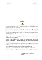
! This is a general manual describing a series of servo speed amplifiers having output capability suitable for driving AC brushless sinusoidal servo motors. This manual may be used in conjunction with appropriate and referenced drawings pertaining to the various specific models. Maintenance procedures should be attempted only by highly skilled technicians having good knowledge of electronics and servo systems with variable speed (EN 60204-1 standard) and using proper test equipment. The conformity with the standards and the "CE" approval is only valid if the items are installed according to the...
Open the catalog to page 3
SEgYODWES&MOTION CONTROL
Open the catalog to page 5
SERVO DBWES& MOTION CONIJtOl
Open the catalog to page 6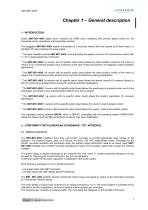
Chapter 1 – General description 1 - INTRODUCTION Series SMT-BD1-400/I digital servo modules are PWM servo amplifiers that provide speed control for AC sinusoidal motors (brushless) with transmitter resolver. The pluggable SMT-BD1-400/I system is available as a multi-axis version that can receive up to three axes in a standard 19" rack including the power supply. * The basic amplifier module SMT-BD1-400/I / a or b provides the speed control for AC synchronous motors with +/- 10 V analog speed input command. * The SMT-BD1-400/I / c version with its specific option board allows the direct position...
Open the catalog to page 7
All control parameters are programmable by means of a serial link and saved in a single EEPROM memory. The auto-configuration and auto-tuning functions allow an easy and quick commissioning of the amplifier. The basic BPCW software, which is IBM-PC compatible with the operating system WINDOWS®, allows the clear display and easy modification of all amplifier parameters. The extended versions of the BPCW software include the digital oscilloscope function as well as some other special functions. 2.2 - REFERENCE TO THE STANDARDS The SMT-BD1-400/I amplifiers operating in the BF rack in 400 VAC, which...
Open the catalog to page 8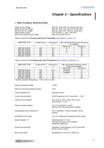
CINFRANOR SERVO DRIVES & MOTION CONTROL Rated DC bus voltage Maximum DC bus voltage Minimum DC bus voltage Rated auxiliary supply Motor phase-phase output voltage 565 VDC, that is 400 VAC rated at rack input 685 VDC, that is max. 480 VAC at rack input 480 VDC, that is min. 340 VAC at rack input 325 VDC(250 V < Uaux < 360 VDC) Output currents for the Fusing mode of the I2t protection (see Chapter 8, section 3.3) Output currents for the Limiting mode of the I2t protection (see Chapter 8, paragraph 3.3) AMPLIFIER TYPE Maximum ambient temperature = + 40° C, fan 2 = 90 l/s. Switching frequency PWM...
Open the catalog to page 9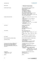
OINFRANOR Speed range Encoder position output Analog outputs (test points) Logic inputs Logic outputs Error display Motor and application parameter setting Automatic functions Conformity with the standards: CE approval with multiaxis power supply configuration BF-400 rack and mains filter F400-35 or 70, "360°" shield; equipotentiality according to the wiring rules. 1 : 2048 with 12 bit input command 1 : 32768 with 16 bit input command Two A and B channels in quadrature with n marker pulse(s) per revolution. Programmable resolution: Accuracy: 8 arc minutes + 1/4 point in standard (2 arc minutes...
Open the catalog to page 10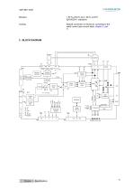
Natural convection or forced air, according to the rated current (see current table, chapter 2, part 1) Resolver conversion Resolver oscillator Current monitor Speed loop Current loops Analog input Analog input EEPROM P err Vmes Vref IQ ID Imes Idc Serial interface Selectable outputs Logic supplies
Open the catalog to page 11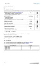
OINFRANOR 3 - MAIN PROTECTIONS 3.1 - Displayed protections
Open the catalog to page 12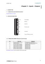
OINFRANOR SERVO DRIVES & MOTION CONTROL 1.1 - CONNECTORS LOCATION WITH BF-400 RACK See Rack BF/400 Vac manual. 1.2 - AMPLIFIER CONNECTORS Faults display Resolver Serial link Encoder output Test and Offset push button See chapter 8, section 2 for the connection of other resolver types. Chapter 3 - Inputs - Outputs
Open the catalog to page 13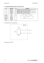
OINFRANOR 3 - X2 POSITION CONNECTOR (Sub D 25 points female) TTL ENCODER OUTPUT SPECIFICATION Chapter 3 - Inputs - Outputs
Open the catalog to page 14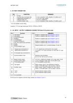
CINFRANOR 4 - X3 TEST CONNECTOR PIN * 10 V for amplifier current rating Linearity = 10 % for logic board type 01612A, 01612B or 01612C. 5 - X4 INPUT - OUTPUT COMMAND CONNECTOR (Sub D 25 points male) For the use of a negative command logic, please see Chapter 8, part 4.1. Chapter 3 - Inputs - Outputs
Open the catalog to page 15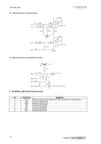
5.1 - SPECIFICATION OF THE ANALOG INPUTS 22 nF 5.2 - SPECIFICATION OF THE LOGIC INPUTS / OUTPUTS Same for IDYN, Power OK 6 - X5 SERIAL LINK (Sub D 9 points male) REMARKS GND (connection of the shield if no "360°" connection on the connector) Transmit data RS 232 Receive data RS 232 Transmit data RS422 Transmit data RS422 Receive data RS422 Receive data RS422 Chapter 3 - Inputs - Outputs
Open the catalog to page 16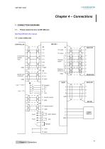
Chapter 4 – Connections 1 - CONNECTION DIAGRAMS 1.1 - POWER CONNECTION WITH THE BF-400 RACK See Rack BF/400 VAC manual. 1.2 - LOGIC CONNECTION Incremental position input Resolver signal Resolver reference Speed input command 11 GND MOTOR 10 Speed monitor POWER SUPPLY
Open the catalog to page 17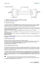
1.3 - SERIAL LINK CONNECTION 2 - WIRING (according to CEI 801 and EN 55011 standards) See enclosed drawings (chapter 8, part 6) 2.1 - GND WIRING AND GROUNDING The reference potential is the earth (ground). Motors and resolvers are grounded via their housing. If a reference of potential is existing, like a main chassis or a cabinet, with a low impedance between the different elements, it should be used to connect ALL reference to it and also connect this reference to the earth (ground). In order to ensure a good equpotentiality between the different elements, remove any paint or isolating material...
Open the catalog to page 18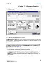
OINFRANOR Chapter 5 - Adjustable functions The BPCW programme is IBM PC compatible with the operating system WINDOWS® and allows a very easy adjustment of the amplifier. INFRANOR digital drive File Setup Advanced functions Utilities Help Analogue input +/-10V Rated speed: 3600 rpm Max speed: 3600 rpm Accel, time: 0.000 s Offset compensation Error message Motor list Encoder resolution [INFRANOR1 - PC GRAPHIC WINDOW (INFRANOR Digital Drive) The INFRANOR Digital Drive graphic window has an adjustment panel, a control panel and functions accessible via menus. This presentation allows a quick adjustment...
Open the catalog to page 19All Infranor Group catalogs and technical brochures
 XtrapulsPac_EN
4 Pages
 XtrapulsGemTemplates_e_1.4
21 Pages
 XtrapulsGem_User_Manual_v1.2.0.64
199 Pages
 XtrapulsGem_Inst_e_2.1
42 Pages
 XtrapulsGem_Inst_e_2.0
42 Pages
 SMTBSi-2Tz_en_2.1
43 Pages
 smt-100
32 Pages
 PacSimBox_d_1
1 Page
 Pac-SF01_flyer_en_18.02
4 Pages
 Pac_User_1.2.1.218
253 Pages
 Pac_Templates_en_1.9
27 Pages
 Pac_STO_Installation_en_2.2
13 Pages
 Pac_SF01_operating_en_1.6
63 Pages
 Pac_SF01_EN
4 Pages
 Pac_Installation_en_2.23
82 Pages
 Pac_flyer_en_17.12
4 Pages
 Option_CT_EMF
6 Pages
 MOVINOR_LH055_LH086_LH097_LH142
23 Pages
 ma_series
6 Pages
 GemSafeTorqueOff_en_1.1
12 Pages
 GemProgramming_e_1.1
47 Pages
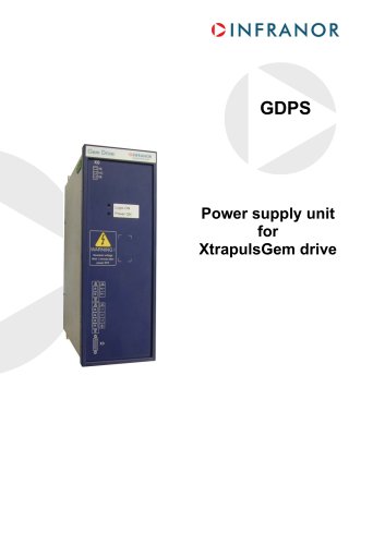 GDPS_old_version_1.1_1
11 Pages
 CD1pm_e_1.2(old)
18 Pages
 CD1pInst_e_7.2(old)
35 Pages
 CD1kInst_e_4.1(old)
40 Pages
 CD1k_CANopenProtocol_e_1.3(old)
86 Pages
 CD1a_e_7.1(old)
45 Pages
 Catalogue gamme SMT-BD1
11 Pages
 BM20A(F)v3_0
20 Pages
 BM20A(D)v3_0
20 Pages
 BF400(GB)v2_2
21 Pages
 BF400(D)v2_2
21 Pages
 BF230(GB)v2_0
23 Pages
 BF230(F)v2_0
23 Pages
 BD2m_e_2.2
69 Pages
 BD2m(GB)2.0
70 Pages
 BD2_e_3.2
53 Pages
 BD2(GB)3.1
53 Pages
 BD2(D)3.1
54 Pages
 Movinor_LH_e
4 Pages
 ma_series
6 Pages
 BD1t(GB)3.1
81 Pages
 BD1t(F)3.0
85 Pages
 BD1pInst(GB)3.0
25 Pages
 BD1pInst(F)3.0
23 Pages
 BD1pInst(D)3.0
24 Pages
 BD1pCD1pUse_e_2.4
57 Pages
 BD1m(GB)5.0
58 Pages
 BD1m(F)5.0
57 Pages
 BD1m(D)v3_3
64 Pages
 BD1k(GB)2.1
35 Pages
 BD1k(F)2.1
36 Pages
 BD1j(GB)v2_41
19 Pages
 BD1j(F)v2_4
21 Pages
 BD1i(GB)v2_21
23 Pages
 BD1i(F)v2_2
27 Pages
 BD1h(F)3.0
65 Pages
 BD1h(D)3.0
59 Pages
 BD1g(GB)v3_0
28 Pages
 BD1g(F)v3_0
28 Pages
 BD1a400(F)v2_3
44 Pages
 BD1a400(D)v2_3
45 Pages
 BD1(GB)7.1_noPW
45 Pages
 BD1(GB)7.1
45 Pages
 BD1(F)7.1_noPW
47 Pages
 BD1(F)7.1
47 Pages
 BD1(D)7.1
45 Pages
 BD1 Katalog
11 Pages
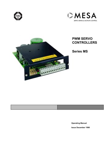 08ma_ms_e_01700
20 Pages
 Easy_User_5.0.1.60.2
190 Pages
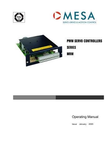 08ma_mrm_em_01575
20 Pages
 01ma_smv_e_01953
40 Pages
 PacHP-SF_Flyer_en_23.06
4 Pages
 IRD_User_Manual_en_1.2.XX.54.rev_b
216 Pages
 PacHP_User_en_1.2.8.100.b
280 Pages
 PacHP_SF02_operating_en_1.6
103 Pages
 PacHP_SF01_operating_en_2.0
63 Pages
 PacHP_Installation_en_2.9
91 Pages
 PacHP_Series_Brochure
8 Pages
 PacHP_Flyer_us_20.10
4 Pages
 IRD_Installation_en_1.5
42 Pages
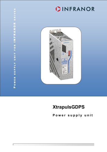 GDPS_Installation_en_4.4
18 Pages
 Easy_STO_en_1.4
14 Pages
 Easy_DB_STO_en_1.2
14 Pages
 Easy_DB_Installation_en_1.4
36 Pages
 CD1pmUser_en_4.2
55 Pages
 CD1pmInst_en_8.15
40 Pages
 CD1k_CANopenProtocol_en_2.10.1.1
108 Pages
 CD1pm_ProfibusProtocol_en_1.5
50 Pages
 CD1kUser_en_2.3
26 Pages
 CD1a_en_8.17
62 Pages
 CD1kInst_en_5.16
46 Pages
 CD1_STO_en_1.8
16 Pages
 CD1_flyer_en_14.09
4 Pages
 Braking_Resistors_en_1.5
10 Pages
 XtracontrolDC2_EN
4 Pages
 Flyer_VisiTouchCNC_EN_V1.1-1
2 Pages
 XtraforsWashdown_EN-2024
2 Pages
 DataSheet_CybIO_CNC_V1.0
6 Pages
 XtraforsPrime_EN-2024
2 Pages
 XtraforsMSS_EN
4 Pages
 XtraforsMSA_EN_2024
2 Pages
 XtraforsEx_EN-2024
2 Pages
 XtraforsBR_EN-2024
2 Pages
 XtraforsBL_EN-2024
2 Pages
 XtraforsBC-ed01-vs3
4 Pages
 Manual_XtraforsPrime
46 Pages
 Drawing_1
1 Page
 Datasheet_MSS
5 Pages
 Datasheet_2
2 Pages
 Datasheet_1
4 Pages
 BLSBLT_series
2 Pages
 BL220221
2 Pages
 BL270
BL2702 Pages
 BL190
BL1902 Pages
 bl100_series
6 Pages
 bl40_series
6 Pages
 BL30
BL302 Pages
 2019-01_XtraforsFP-DSL_FR
4 Pages
 Movinor_T_EN
4 Pages
 Movinor_N_EN
4 Pages
 Movinor_Low_Voltage_EN
4 Pages
 Manual Movinor T 03-2026
46 Pages
 Manual Movinor N 03-2026
63 Pages
 XtrapulsEasy™ AC servo-drive
4 Pages
 XtrapulsCD1 AC servo-drives
4 Pages
 CybIO
CybIO6 Pages
 AC SERVOMOTORS
2 Pages
 Movinor® N AC Servomotors
4 Pages






Archived catalogs
 AN_CD1ak_AbsoluteEncoder_en_2.0
10 Pages
 AN_CD1ak_SinCosTracks_e_1.0
7 Pages
 AN_CD1pm_AbsoluteEncoder_en_2.0
10 Pages
 AN_CD1pm_SinCosTracks_e_1.0
7 Pages
 AN_DC_bus_interfacing_en_1.3
5 Pages
 CD1_EC_conformity_24.05
1 Page
 CD1_STO_conformity_19.02
2 Pages
 EtherCAT Interface_en_1.3
20 Pages
 Easy_EC_Conformity_24_10
1 Page
 GDPS_EC_conformity_24.07
1 Page
 IRD_EC_Conformity_25.03
1 Page
 PacHP_TÜV_certificate_25.07
2 Pages
 BD1c(F)v2_01
19 Pages
 BD1c(GB)v2_01
19 Pages
 BD1d(F)v2_01
25 Pages
 BD1d(GB)v2_01
25 Pages
 BD1e(F)v2_01
22 Pages
 BD1f(F)v2_01
17 Pages
 BD1f(GB)v2_01
18 Pages
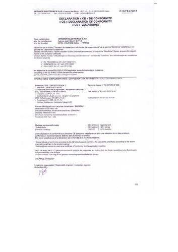 CE_conformity_Gem
1 Page
 Pac_EC_conformity_25.04
1 Page
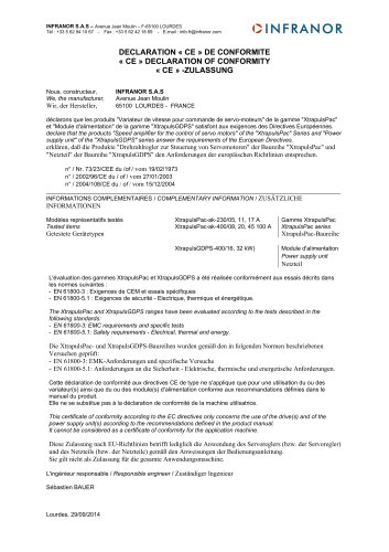 Pac_GDPS_CEconformity
1 Page
![SMT100D_e_1.01[1]](https://img.directindustry.com/pdf/repository_di/4620720/smt100d-e-101-1-1141223_1mg.jpg) SMT100D_e_1.01[1]
SMT100D_e_1.01[1]40 Pages
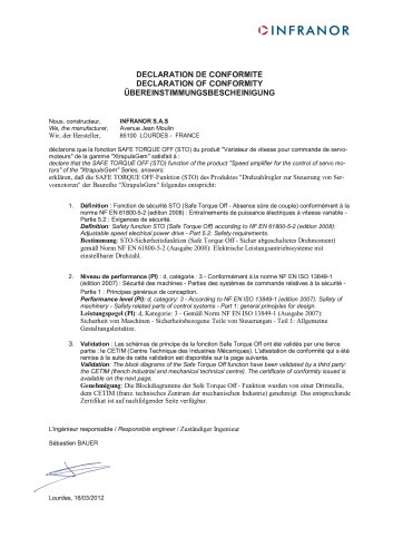 STO_declaration_Gem
2 Pages