
- Catalogs
- Infranor Group
- BD1a400(D)v2_3


BD1a400(D)v2_3

BD1a400(D)v2_3
Catalog excerpts
SERVO DRIVES & MOTION CONTROL
Open the catalog to page 1
SMT-BD1/400 ALLGEMEINE SICHERHEITSINFORMATIONEN Betriebsanleitung Dieses Informationsblatt mit den Warnhinweisen gilt als Zusatz zur produktspezifischen Betriebsanleitung und muß aus Sicherheitsgründen besonders beachtet werden. Diese elektrischen Maschinen bzw. Geräte sind Betriebsmittel zum Einsatz in industriellen Starkstromanlagen. Während des Betriebes haben diese Betriebsmittel gefährliche, spannungsführende blanke Teile, ggf. auch bewegte bzw. rotierende Teile. Sie könnten deshalb bei unzulässigem Entfernen der erforderlichen Abdeckungen, bei unsachgemäßem Einsatz, falscher Bedienung oder...
Open the catalog to page 3
SERVO DRIVES & MOTION CONTROL 3.3 - MOTORWELLE BLOCKIERT, SCHWINGUNGEN BZW. LAUF BEI HOCHSTDREHZAHL. 32
Open the catalog to page 6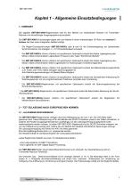
Kapitel 1 - Allgemeine Einsatzbedingungen 1- VORWORT Die digitalen SMT-BD1/400/I-Reglermodule sind für den Betrieb von bürstenlosen Motoren mit TransmitterResolver und sinusförmiger Ausgangsspannung konzipiert. Der SMT-BD1/400/I-Einschubregler eignet sich zum Betrieb in einem mehrachsigen 19"-Rack von maximal 3 Achsen das über einen integrierten Netzteil verfügt. * Die Regler-Grundausführungen SMT-BD1/400/I/a oder b sind für die Drehzahlregelung von bürstenlosen Synchronmotoren mit analogem +/- 10 V-Drehzahlsollwert konzipiert. Die SMT-BD1/400/I/c-Version (Option) mit spezifischem Optionsprint...
Open the catalog to page 7
Sämtliche Steuerungsparameter sind mittels serieller Schnittstelle programmierbar und werden in ein einziges EEPROM gespeichert. Die Funktionen Auto-configuration und Auto-tuning gewährleisten eine einfache und schnelle Inbetriebnahme des Reglers. Die mit dem WINDOWS®-Betriebssystem IBM-PC kompatible Grund-Software BPCW ermöglicht die klare Bildschirmanzeige sowie die einfache Änderung sämtlicher Reglerparameter. Die erweiterte BPCW-Software Version beinhaltet die Digitaloszilloskop-Funktion sowie einige andere Sonderfunktionen. 2.2 - GERÄTESPEZIFISCHE NORMEN Die im - mit BF35-Netzfilter versehenen...
Open the catalog to page 8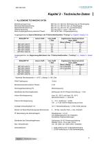
CINFRANOR SERVO DRIVES & MOTION CONTROL 1 - ALLGEMEINE TECHNISCHE DATEN 565 VDC d.h. 400 VAC Nennspannung am Rackeingang 685 VDC d.h. 480 VAC max. am Rackeingang 480 VDC d.h. 340 VAC min. am Rackeingang 325 VDC (250 V < Uaux < 360 VDC) Betriebsnennspannung Maximale Betriebsspannung Mindestbetriebsspannung Hilfsnennspannung Motor-Ausgangsspannung zwischen Phasen Ausgangsstrome bei Sperre-Betriebsart der I2t-Sicherheitsfunktion ("Fusing") (s. Kapitel 8, Absatz 3.3) * Maximale Raumtemperatur = + 40°C, Luftertyp 2 PWM-T aktfrequenz Mindestinduktivitat zwischen Phasen Stromreglerbeschaltung (PI) Bandbreite...
Open the catalog to page 9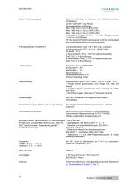
CINFRANOR Geber-Positionsausgang Zwei A- u. B-Kanale in Quadratur mit n Nullimpuls(en) pro Programmierbare Auflosung: Genauigkeit: 8 Bogenminuten + 1/4 Imp. (2 Bogenminuten + 1/4 Imp. auf Anfrage) (*) Die gesamte Positionsgenauigkeit muG die Genauigkeit des verwendeten Resolvers berucksichtigen. Analogausgange (Teststecker) • Stromistwert (Imes): ± 10 V fur ReglerstromgroGe, Freigabe / Sperre: FREIGABE Endschalter +: FC+ Endschalter - : FC-Stromsollwert: CI Nulldrehzahlsollwert: CV0 Fehlerruckstellung: RAZ Relaiskontakt Umax = 50 V, Imax = 100 mA, Pmax = 5 W • "Regler bereit": geschlossen wenn...
Open the catalog to page 10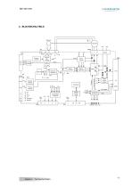
Analogeingang EEPROM P err Vmes Vref IQ ID Imes Idc Analogeingang fc+ fcCV0 CI Freigabe RESET 1/6 Kapitel 2 - Technische Daten auswählbare Ausgänge serielle schnittstelle
Open the catalog to page 11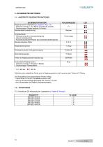
CINFRANOR 3 - SICHERHEITSFUNKTIONEN3.1 - ANGEZEIGTE SICHERHEITSFUNKTIONEN SICHERHEITSFUNKTION Samtliche oben aufgefuhrte Fehler sind im Regler gespeichert mit Ausnahme des "Undervolt."-Fehlers. Die Ruckstellung eines gespeicherten Fehlers erfolgt: - mittels RESET-Funktion, der BPCW-Software oder - uber den Fehlerruckstellungseingang (X4, Klemme 13) oder - durch Ausschalten der Regler-Leistungsversorgung. F2 : Kontrolle der DC-Versorgung der Logikplatine (s. Kapitel 8 "Anhang") Kapitel 2 - Technische Daten
Open the catalog to page 12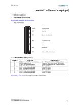
OINFRANOR SERVO DRIVES & MOTION CONTROL 1.1 - STECKER DES BF/400-RACKS Siehe Bedienungsanleitung des BF/400-Racks. Serielle Schnittstelle Siehe Kapitel 8, Abs. 2 fur den AnschluG von sonstigen Resolvertypen.
Open the catalog to page 13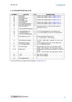
CINFRANOR 5 - X4: STEUERSTECKER (Sub D 25) KLEMMEN Fur die Anwendung einer negativen Steuerungslogik, s. Kapitel 8, Abs. 4.1.
Open the catalog to page 15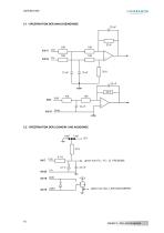
5.2 - SPEZIFIKATION DER LOGIKEIN- UND AUSGÄNGE 4,7 K gleich fuer FC+, FC-, CI, FREIGABE 4,7 V gleich fuer Idyn, LEISTUNG BEREIT
Open the catalog to page 16
CINFRANOR 6 - X5: SERIELLE SCHNITTSTELLE (Sub D 9-Stecker) KLEMMEN
Open the catalog to page 17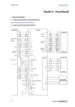
Kapitel 4 - Anschlüsse 1 - ANSCHLUSSPLÄNE 1.1 – ANSCHLUSS DER BF/400 VAC-RACKNETZTEILE Siehe Bedienungsanleitung des BF/400-Racks. 1.2 – ANSCHLUSS DER REGLERSTEUERUNG Inkrementaler LageEingang Resolver Signal Resolver Referenz REGLER BEREIT
Open the catalog to page 18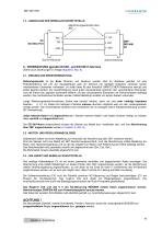
1.3 - ANSCHLUSS DER SERIELLEN SCHNITTSTELLE Abschirmungsanschluß über 360° 2 - VERDRAHTUNG (gemäß CEI 801- und EN 55011-Normen) (Siehe auch Zeichnungen in Anlage (Kapitel 8, Abs. 6) 2.1 - ERDUNG UND ERDEVERDRAHTUNG Referenzpotential ist die Erde. Motoren und Resolver werden über ihr Gehäuse geerdet. Ist eine Potentialreferenz wie z.B. ein Hauptgehäuse oder ein Schrank mit niedriger Impedanz zwischen seinen verschiedenen Elementen vorhanden, so sollte diese für den Anschluß SÄMTLICHER Referenzen benutzt und selbst geerdet werden. Zur Gewährleistung eines guten Äquipotentials zwischen den verschiedenen...
Open the catalog to page 19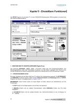
OINFRANOR SERVO DRIVES & MOTION CONTROL Das BPCW-Programm ist auf jedem PC mit dem WINDOWS®-Betriebssystem IBM-kompatibel und erlaubt eine sehr einfache Reglereinstellung. INFRANOR digital drive Z.50 Datei Einstellungen Spezielle Funktionen Werkzeuge Hilfe Drehzahl U/M Sollwert: Fehlermeldung Strom Offset Kompensation Das graphische INFRANOR Digital Drive - PC-Fenster verfugt uber eine Einstellungsoberflache, eine Steuerungsoberflache sowie uber verschiedene Funktionen, die uber Menus zuganglich sind. Damit ist eine schnelle Einstellung der System-Hauptparameter wahrend der Inbetriebnahme und...
Open the catalog to page 20All Infranor Group catalogs and technical brochures
 XtrapulsPac_EN
4 Pages
 SMTBSi-2Tz_en_2.1
43 Pages
 PacSimBox_d_1
1 Page
 Pac-SF01_flyer_en_18.02
4 Pages
 Pac_User_1.2.1.218
253 Pages
 Pac_Templates_en_1.9
27 Pages
 Pac_STO_Installation_en_2.2
13 Pages
 Pac_SF01_operating_en_1.6
63 Pages
 Pac_SF01_EN
4 Pages
 Pac_Installation_en_2.23
82 Pages
 Pac_flyer_en_17.12
4 Pages
 Option_CT_EMF
6 Pages
 MOVINOR_LH055_LH086_LH097_LH142
23 Pages
 ma_series
6 Pages
 GemSafeTorqueOff_en_1.1
12 Pages
 CD1pm_e_1.2(old)
18 Pages
 CD1pInst_e_7.2(old)
35 Pages
 CD1kInst_e_4.1(old)
40 Pages
 CD1k_CANopenProtocol_e_1.3(old)
86 Pages
 CD1a_e_7.1(old)
45 Pages
 Catalogue gamme SMT-BD1
11 Pages
 BM20A(F)v3_0
20 Pages
 BM20A(D)v3_0
20 Pages
 BF400(GB)v2_2
21 Pages
 BF400(D)v2_2
21 Pages
 BF230(GB)v2_0
23 Pages
 BF230(F)v2_0
23 Pages
 BD2m_e_2.2
69 Pages
 BD2m(GB)2.0
70 Pages
 BD2_e_3.2
53 Pages
 BD2(GB)3.1
53 Pages
 BD2(D)3.1
54 Pages
 Movinor_LH_e
4 Pages
 ma_series
6 Pages
 BD1t(GB)3.1
81 Pages
 BD1t(F)3.0
85 Pages
 BD1pInst(GB)3.0
25 Pages
 BD1pInst(F)3.0
23 Pages
 BD1pInst(D)3.0
24 Pages
 BD1pCD1pUse_e_2.4
57 Pages
 BD1m(GB)5.0
58 Pages
 BD1m(F)5.0
57 Pages
 BD1m(D)v3_3
64 Pages
 BD1k(GB)2.1
35 Pages
 BD1k(F)2.1
36 Pages
 BD1j(GB)v2_41
19 Pages
 BD1j(F)v2_4
21 Pages
 BD1i(GB)v2_21
23 Pages
 BD1i(F)v2_2
27 Pages
 BD1h(F)3.0
65 Pages
 BD1h(D)3.0
59 Pages
 BD1g(GB)v3_0
28 Pages
 BD1g(F)v3_0
28 Pages
 BD1a400(GB)v2_3
43 Pages
 BD1a400(F)v2_3
44 Pages
 BD1(GB)7.1_noPW
45 Pages
 BD1(GB)7.1
45 Pages
 BD1(F)7.1_noPW
47 Pages
 BD1(F)7.1
47 Pages
 BD1(D)7.1
45 Pages
 BD1 Katalog
11 Pages
 Easy_User_5.0.1.60.2
190 Pages
 01ma_smv_e_01953
40 Pages
 PacHP-SF_Flyer_en_23.06
4 Pages
 IRD_User_Manual_en_1.2.XX.54.rev_b
216 Pages
 PacHP_User_en_1.2.8.100.b
280 Pages
 PacHP_SF02_operating_en_1.6
103 Pages
 PacHP_SF01_operating_en_2.0
63 Pages
 PacHP_Installation_en_2.9
91 Pages
 PacHP_Series_Brochure
8 Pages
 PacHP_Flyer_us_20.10
4 Pages
 IRD_Installation_en_1.5
42 Pages
 Easy_STO_en_1.4
14 Pages
 Easy_DB_STO_en_1.2
14 Pages
 Easy_DB_Installation_en_1.4
36 Pages
 CD1pmUser_en_4.2
55 Pages
 CD1pmInst_en_8.15
40 Pages
 CD1k_CANopenProtocol_en_2.10.1.1
108 Pages
 CD1pm_ProfibusProtocol_en_1.5
50 Pages
 CD1kUser_en_2.3
26 Pages
 CD1a_en_8.17
62 Pages
 CD1kInst_en_5.16
46 Pages
 CD1_STO_en_1.8
16 Pages
 CD1_flyer_en_14.09
4 Pages
 Braking_Resistors_en_1.5
10 Pages
 XtracontrolDC2_EN
4 Pages
 Flyer_VisiTouchCNC_EN_V1.1-1
2 Pages
 XtraforsWashdown_EN-2024
2 Pages
 DataSheet_CybIO_CNC_V1.0
6 Pages
 XtraforsPrime_EN-2024
2 Pages
 XtraforsMSS_EN
4 Pages
 XtraforsMSA_EN_2024
2 Pages
 XtraforsEx_EN-2024
2 Pages
 XtraforsBR_EN-2024
2 Pages
 XtraforsBL_EN-2024
2 Pages
 XtraforsBC-ed01-vs3
4 Pages
 Manual_XtraforsPrime
46 Pages
 Drawing_1
1 Page
 Datasheet_MSS
5 Pages
 Datasheet_2
2 Pages
 Datasheet_1
4 Pages
 BLSBLT_series
2 Pages
 BL220221
2 Pages
 BL270
BL2702 Pages
 BL190
BL1902 Pages
 bl100_series
6 Pages
 bl40_series
6 Pages
 BL30
BL302 Pages
 2019-01_XtraforsFP-DSL_FR
4 Pages
 Movinor_T_EN
4 Pages
 Movinor_N_EN
4 Pages
 Movinor_Low_Voltage_EN
4 Pages
 Manual Movinor T 03-2026
46 Pages
 Manual Movinor N 03-2026
63 Pages
 XtrapulsEasy™ AC servo-drive
4 Pages
 XtrapulsCD1 AC servo-drives
4 Pages
 CybIO
CybIO6 Pages
 AC SERVOMOTORS
2 Pages
 Movinor® N AC Servomotors
4 Pages






Archived catalogs
 AN_CD1ak_AbsoluteEncoder_en_2.0
10 Pages
 AN_CD1ak_SinCosTracks_e_1.0
7 Pages
 AN_CD1pm_AbsoluteEncoder_en_2.0
10 Pages
 AN_CD1pm_SinCosTracks_e_1.0
7 Pages
 AN_DC_bus_interfacing_en_1.3
5 Pages
 CD1_EC_conformity_24.05
1 Page
 CD1_STO_conformity_19.02
2 Pages
 EtherCAT Interface_en_1.3
20 Pages
 Easy_EC_Conformity_24_10
1 Page
 GDPS_EC_conformity_24.07
1 Page
 IRD_EC_Conformity_25.03
1 Page
 PacHP_TÜV_certificate_25.07
2 Pages
 BD1c(F)v2_01
19 Pages
 BD1c(GB)v2_01
19 Pages
 BD1d(F)v2_01
25 Pages
 BD1d(GB)v2_01
25 Pages
 BD1e(F)v2_01
22 Pages
 BD1f(F)v2_01
17 Pages
 BD1f(GB)v2_01
18 Pages
 Pac_EC_conformity_25.04
1 Page




















