
- Catalogs
- Infranor Group
- BD1(F)7.1_noPW


BD1(F)7.1_noPW

BD1(F)7.1_noPW
The document provides detailed specifications and procedures for operating a motor control system. It includes logic levels for control signals, voltage requirements for inputs and outputs, and specific connectors for serial communication. Emphasis is placed on proper grounding and shielding to comply with standards like CEI 801 and EN55011.
Characteristics of analog inputs, such as current and speed command inputs, and logic inputs like ENABLE and fault reset are specified. Voltage levels and conditions for these inputs and outputs are detailed.
Detailed schematics for connecting power supplies, motors, and control units are provided, highlighting the importance of proper grounding and shielding.
The document stresses the use of shielded cables and proper grounding techniques to minimize interference and ensure reliable operation, with specific recommendations for motor, resolver, analog command, and serial communication cables.
The BPCW software is used for adjusting motor controller parameters, including speed and current limits, encoder resolution, and auto-tuning features for optimal performance.
Instructions for saving and loading parameter files and storing parameters in the EEPROM of the controller are provided to retain settings after power-off.
- Ensure all connections are made with the power off.
- Use shielded cables and proper grounding to prevent interference.
- Follow specified voltage levels and logic conditions for inputs and outputs.
- Utilize the BPCW software for precise control and adjustment of motor parameters.
The drive is initialized with parameters stored in the EEPROM, automatically loaded when the BPCW software is restarted. The setup menu allows setting the PC communication port and serial transmission speed, with configurations savable to a file.
Motor Parameters: The AUTOPHASING PROCEDURE identifies motor parameters for motors not in the MOTOR LIST. Users can define parameters like Pole pairs, Phase order, and Resolver offset.
Controller Parameters: The speed controller structure includes adjustable gain parameters, automatically calculated during AUTO-TUNING.
Analogue Input Filter: Sets the cutoff frequency for the speed command filter.
Pulse Input Mode: Disables incremental mode, reverting to standard speed mode.
Read Drive Status: Displays the status of logical inputs and drive faults.
Digitizing Oscilloscope: Provides a graphical view of drive command signals.
Drive Configuration Verification: Standard configuration includes resolver adaptation and current loop adaptation.
Powering the Drive: Ensure correct auxiliary and power supply voltages.
Drive Startup and Adjustment: Connect the RS 232 serial link, ensure correct software configuration, and perform AUTO-TUNING.
Adapting to a New Motor: Use the AUTO-PHASING PROCEDURE and CURRENT PHASE LEAD CALCULATION for motors not in the MOTOR LIST.
Speed Loop Adjustment with Vertical Load: Perform AUTO-TUNING with the motor decoupled and then coupled to the load.
Two methods for controlling the load are described: AUTO-TUNING with the motor decoupled and coupling the motor to the load. Detailed steps for executing these methods are provided.
A comprehensive guide to diagnosing and eliminating system faults is provided, categorizing faults into system faults, memorized faults, and specific fault types.
Troubleshooting steps for common malfunctions like no motor reaction and motor oscillations are provided.
Guidelines for replacing a drive on a machine emphasize hardware configuration consistency and proper EEPROM parameter installation.
Details on hardware adaptations for the SMT-BD1 drive module, including adaptations for different motor types and current loops, are provided.
Tables and diagrams illustrating hardware adaptations and resolver transformation ratios are included.
Specifications for discharge resistance and jumper selection for different power ranges are provided.
Instructions for adapting to non-standard MAVILOR motor resolvers are provided.
Details on temperature sensor configurations, current loops, and I2t protection are provided.
Logical inputs configuration and end-of-travel inputs are detailed.
Instructions for installing BPCW software under Windows are provided.
Guidelines for maintaining uninterrupted shielding along cable length are provided.
Steps for installation and setup of cogging torque compensation are outlined.
Steps for verifying cogging torque compensation are provided.
Warnings related to cogging torque compensation are provided.
Various drive and software configurations are described.
Catalog excerpts
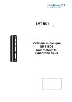
SERVO DRIVES & MOTION CONTROL pour moteur AC synchrone sinus
Open the catalog to page 1
! Ce manuel produit concerne une série de variateurs destinés à l'asservissement des moteurs AC synchrones sinus. Celui-ci doit être utilisé en coordination avec les schémas référencés et adéquats aux différents modèles. Pour les instructions de stockage, d'utilisation après stockage, de mise en service ainsi que pour tous les détails techniques, la lecture du manuel d'utilisation est OBLIGATOIRE avant toute mise en œuvre. L'accès à ce matériel ainsi que son utilisation doivent être strictement réservés au personnel qualifié ayant des connaissances approfondies de l’électronique et des systèmes...
Open the catalog to page 3
Sommaire PAGE
Open the catalog to page 5
SERVO DRIVES & MOTION CONTROL
Open the catalog to page 6
1- INTRODUCTION Les modules variateurs numériques à commande PWM sinusoïdale de la série SMT-BD1 sont destinés à piloter des moteurs sans balai équipés d'un résolveur transmetteur. Le système SMT-BD1 enfichable a une présentation bloc monoaxe ou une présentation multiaxes, étudiée de façon à pouvoir disposer d'un maximum de 6 axes dans un rack standard 19 pouces. Chacune de ces présentations dispose d'un bloc alimentation intégré. * Les modules variateur de base SMT-BD1/a ou b permettent de contrôler la vitesse du moteur à partir d'une consigne de vitesse analogique ±10 V. La version SMT-BD1/c,...
Open the catalog to page 7
Le logiciel de base BPCW, compatible PC avec l'environnement WINDOWS®, permet de visualiser de façon claire et de modifier facilement l'ensemble des paramètres du variateur. Les versions étendues du logiciel BPCW, incluent la fonction oscilloscope digital et certaines fonctions spéciales. 2.2 - REFERENCE AUX NORMES APPLICABLES Les variateurs SMT-BD1, montés dans le rack BF, équipés du filtre secteur référence BF 35/70, ont été certifiés conformes aux normes de compatibilité électromagnétique : - EN 55011, groupe 1, classe A, concernant les perturbations radioélectriques, conduites et rayonnées,...
Open the catalog to page 8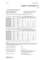
CINFRANOR SERVO DRIVES & MOTION CONTROL 1 - DONNEES TECHNIQUES PRINCIPALES Tension d'alimentation de puissance Tension d'alimentation auxiliaire Tension de sortie phase-phase moteur 310 VDC (270 V < Bus DC < 340 VDC Max) 310 VDC (200 V < Uaux < 340 VDC Max) 200 Veff pour Bus DC 310 VDC Tableau des courants de sortie pour une protection I2t en mode "fusing" (cf. chapitre 8, § 3.3). * Temperature ambiante maximale de 40° C, ventilation 1 = 56 l/s, ventilation 2 = 90 l/s. Les modeles SMT-BD1-X/Xr sont equipes d'un radiateur complementaire afin d'ameliorer l'evacuation des pertes joules et augmenter...
Open the catalog to page 9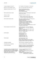
Consigne analogique de vitesse CV ±10 V résolution 12 bits standard ou 16 bits option Plage de la rampe accél/décél. moteur De 0 s à 30 s entre vitesse nulle et vitesse max. Régulateur de vitesse de type P, PI ou PI2 Période d'échantillonnage de 0,5 ms Système antisaturation de l'intégrateur Filtre antirésonance Gains numériques ajustables Bande passante boucle de vitesse Fréquence de coupure pour déphasage 45° sélectionnable : 50 Hz, 75 Hz ou 100 Hz Ajustable de 100 tr/min à 14 000 tr/min 1 : 2 048 pour résolution entrée consigne 12 bits 1 : 32 768 pour résolution entrée consigne 16 bits Sortie...
Open the catalog to page 10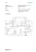
Température - stockage -20° C à +70° C - fonctionnement +5° C à +40° C A partir de 40° C, les courants nominaux doivent être réduits de 3% par degré Celsius Température maximale : 50° C Convection naturelle ou ventilation forcée en fonction du courant nominal (voir tableau des courants, chap. 2, § 1) Conversion capteur résolveur Oscillateur résolveur Mesure courant Entrée analogique Mémoire EEPROM Entrée analogique P err Vmes Vref IQ ID Imes Idc Boucles courant Contrôle vectoriel Boucle vitesse Interface série Sorties sélectionnables Alims logiques Sécurités défau
Open the catalog to page 11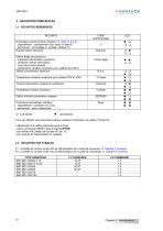
OINFRANOR 3 - SECURITES PRINCIPALES 3.1 - SECURITES MEMORISEES
Open the catalog to page 12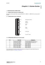
CINFRANOR SERVO DRIVES & MOTION CONTROL Se reporter au manuel produit Blocs monoaxe SMT-BM 20 A - BMM 05 F - BMM 05 AF et au manuel produit Rack BF. 2 - X1 PRISE RESOLVEUR Sub D 9 points femelle Pour le branchement de resolveurs, autres que les resolveurs qui equipent les moteurs MAVILOR dans leur presentation standard, voir chapitre 8 (Annexes) § 2.
Open the catalog to page 13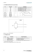
OINFRANOR 3 - X2 PRISE POSITION Sub D 25 points femelle PIN Recepteur de ligne conseille : 26LS32. * : 10 V pour calibre courant variateur Linearite 10% pour carte logique de type 01612A, 01612B ou 01612C.
Open the catalog to page 14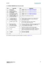
CINFRANOR 5 - X4 PRISE COMMANDE Sub D 25 points male PIN Pour I'utilisation d'une logique de commande negative, se reporter au chapitre 8, § 4.1.
Open the catalog to page 15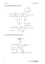
5.1 - SPECIFICATION DES ENTREES ANALOGIQUES 22 nF 5.2 - SPECIFICATION DES ENTREES/SORTIES LOGIQUES 4,7 K Idem pour FC+, FC-, CI, ENABLE 4,7 V Idem pour IDYN, POK
Open the catalog to page 16
CINFRANOR 6 - X5 PRISE LIAISON SERIE Sub D 9 points male
Open the catalog to page 17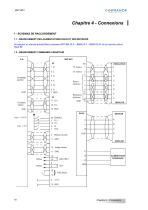
Chapitre 4 - Connexions 1 - SCHEMAS DE RACCORDEMENT 1.1 - BRANCHEMENT DES ALIMENTATIONS RACK ET DES MOTEURS Se reporter au manuel produit Blocs monoaxe SMT-BM 20 A – BMM 05 F – BMM 05 AF et au manuel produit Rack BF. 1.2 - BRANCHEMENT COMMANDE VARIATEUR SMT-BD1 Comptage position Retour résolveur Référence résolveur Mesure courant 11 GND MAVILOR 10 Image vitesse ALIMENTATION PUISSANCE
Open the catalog to page 18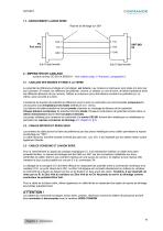
1.3 - BRANCHEMENT LIAISON SERIE Reprise de blindage sur 360° 2 - IMPERATIFS DE CABLAGE suivant normes CEI 801 et EN55011 : Voir schéma chap. 8 "Annexes", paragraphe 6. 2.1 - CABLAGE DES MASSES ET MISE A LA TERRE Le potentiel de référence privilégié et à privilégier, est la terre. Les moteurs et résolveurs sont reliés à la terre par leur carcasse. S'il existe une référence de potentiel, comme un châssis ou une armoire, de faible impédance entre les différents éléments de son volume, l'utiliser au maximum pour des liaisons courtes à ce potentiel qui, luimême, sera raccordé à la terre. L'existence...
Open the catalog to page 19All Infranor Group catalogs and technical brochures
 XtrapulsPac_EN
4 Pages
 SMTBSi-2Tz_en_2.1
43 Pages
 PacSimBox_d_1
1 Page
 Pac-SF01_flyer_en_18.02
4 Pages
 Pac_User_1.2.1.218
253 Pages
 Pac_Templates_en_1.9
27 Pages
 Pac_STO_Installation_en_2.2
13 Pages
 Pac_SF01_operating_en_1.6
63 Pages
 Pac_SF01_EN
4 Pages
 Pac_Installation_en_2.23
82 Pages
 Pac_flyer_en_17.12
4 Pages
 Option_CT_EMF
6 Pages
 MOVINOR_LH055_LH086_LH097_LH142
23 Pages
 ma_series
6 Pages
 GemSafeTorqueOff_en_1.1
12 Pages
 CD1pm_e_1.2(old)
18 Pages
 CD1pInst_e_7.2(old)
35 Pages
 CD1kInst_e_4.1(old)
40 Pages
 CD1k_CANopenProtocol_e_1.3(old)
86 Pages
 CD1a_e_7.1(old)
45 Pages
 Catalogue gamme SMT-BD1
11 Pages
 BM20A(F)v3_0
20 Pages
 BM20A(D)v3_0
20 Pages
 BF400(GB)v2_2
21 Pages
 BF400(D)v2_2
21 Pages
 BF230(GB)v2_0
23 Pages
 BF230(F)v2_0
23 Pages
 BD2m_e_2.2
69 Pages
 BD2m(GB)2.0
70 Pages
 BD2_e_3.2
53 Pages
 BD2(GB)3.1
53 Pages
 BD2(D)3.1
54 Pages
 Movinor_LH_e
4 Pages
 ma_series
6 Pages
 BD1t(GB)3.1
81 Pages
 BD1t(F)3.0
85 Pages
 BD1pInst(GB)3.0
25 Pages
 BD1pInst(F)3.0
23 Pages
 BD1pInst(D)3.0
24 Pages
 BD1pCD1pUse_e_2.4
57 Pages
 BD1m(GB)5.0
58 Pages
 BD1m(F)5.0
57 Pages
 BD1m(D)v3_3
64 Pages
 BD1k(GB)2.1
35 Pages
 BD1k(F)2.1
36 Pages
 BD1j(GB)v2_41
19 Pages
 BD1j(F)v2_4
21 Pages
 BD1i(GB)v2_21
23 Pages
 BD1i(F)v2_2
27 Pages
 BD1h(F)3.0
65 Pages
 BD1h(D)3.0
59 Pages
 BD1g(GB)v3_0
28 Pages
 BD1g(F)v3_0
28 Pages
 BD1a400(GB)v2_3
43 Pages
 BD1a400(F)v2_3
44 Pages
 BD1a400(D)v2_3
45 Pages
 BD1(GB)7.1_noPW
45 Pages
 BD1(GB)7.1
45 Pages
 BD1(F)7.1
47 Pages
 BD1(D)7.1
45 Pages
 BD1 Katalog
11 Pages
 Easy_User_5.0.1.60.2
190 Pages
 01ma_smv_e_01953
40 Pages
 PacHP-SF_Flyer_en_23.06
4 Pages
 IRD_User_Manual_en_1.2.XX.54.rev_b
216 Pages
 PacHP_User_en_1.2.8.100.b
280 Pages
 PacHP_SF02_operating_en_1.6
103 Pages
 PacHP_SF01_operating_en_2.0
63 Pages
 PacHP_Installation_en_2.9
91 Pages
 PacHP_Series_Brochure
8 Pages
 PacHP_Flyer_us_20.10
4 Pages
 IRD_Installation_en_1.5
42 Pages
 Easy_STO_en_1.4
14 Pages
 Easy_DB_STO_en_1.2
14 Pages
 Easy_DB_Installation_en_1.4
36 Pages
 CD1pmUser_en_4.2
55 Pages
 CD1pmInst_en_8.15
40 Pages
 CD1k_CANopenProtocol_en_2.10.1.1
108 Pages
 CD1pm_ProfibusProtocol_en_1.5
50 Pages
 CD1kUser_en_2.3
26 Pages
 CD1a_en_8.17
62 Pages
 CD1kInst_en_5.16
46 Pages
 CD1_STO_en_1.8
16 Pages
 CD1_flyer_en_14.09
4 Pages
 Braking_Resistors_en_1.5
10 Pages
 XtracontrolDC2_EN
4 Pages
 Flyer_VisiTouchCNC_EN_V1.1-1
2 Pages
 XtraforsWashdown_EN-2024
2 Pages
 DataSheet_CybIO_CNC_V1.0
6 Pages
 XtraforsPrime_EN-2024
2 Pages
 XtraforsMSS_EN
4 Pages
 XtraforsMSA_EN_2024
2 Pages
 XtraforsEx_EN-2024
2 Pages
 XtraforsBR_EN-2024
2 Pages
 XtraforsBL_EN-2024
2 Pages
 XtraforsBC-ed01-vs3
4 Pages
 Manual_XtraforsPrime
46 Pages
 Drawing_1
1 Page
 Datasheet_MSS
5 Pages
 Datasheet_2
2 Pages
 Datasheet_1
4 Pages
 BLSBLT_series
2 Pages
 BL220221
2 Pages
 BL270
BL2702 Pages
 BL190
BL1902 Pages
 bl100_series
6 Pages
 bl40_series
6 Pages
 BL30
BL302 Pages
 2019-01_XtraforsFP-DSL_FR
4 Pages
 Movinor_T_EN
4 Pages
 Movinor_N_EN
4 Pages
 Movinor_Low_Voltage_EN
4 Pages
 Manual Movinor T 03-2026
46 Pages
 Manual Movinor N 03-2026
63 Pages
 XtrapulsEasy™ AC servo-drive
4 Pages
 XtrapulsCD1 AC servo-drives
4 Pages
 CybIO
CybIO6 Pages
 AC SERVOMOTORS
2 Pages
 Movinor® N AC Servomotors
4 Pages






Archived catalogs
 AN_CD1ak_AbsoluteEncoder_en_2.0
10 Pages
 AN_CD1ak_SinCosTracks_e_1.0
7 Pages
 AN_CD1pm_AbsoluteEncoder_en_2.0
10 Pages
 AN_CD1pm_SinCosTracks_e_1.0
7 Pages
 AN_DC_bus_interfacing_en_1.3
5 Pages
 CD1_EC_conformity_24.05
1 Page
 CD1_STO_conformity_19.02
2 Pages
 EtherCAT Interface_en_1.3
20 Pages
 Easy_EC_Conformity_24_10
1 Page
 GDPS_EC_conformity_24.07
1 Page
 IRD_EC_Conformity_25.03
1 Page
 PacHP_TÜV_certificate_25.07
2 Pages
 BD1c(F)v2_01
19 Pages
 BD1c(GB)v2_01
19 Pages
 BD1d(F)v2_01
25 Pages
 BD1d(GB)v2_01
25 Pages
 BD1e(F)v2_01
22 Pages
 BD1f(F)v2_01
17 Pages
 BD1f(GB)v2_01
18 Pages
 Pac_EC_conformity_25.04
1 Page




















