- Catalogs
- Infranor Group
- 08ma_ms_e_01700


08ma_ms_e_01700
1 /20Pages
08ma_ms_e_01700
1 /20Pages
Catalog excerpts
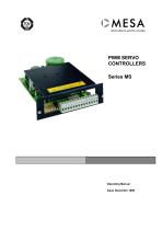
CMESA SERVO-DRIVES & MOTION CONTROL Operating Manual
Open the catalog to page 1
MESA Automation GmbH RECEIVING AND HANDLING Upon delivery of the equipment, inspect the shipping containers and contents for indications of damages in curried in transit. If any of the items specified in the bill of lading are damaged, or the quantity is incorrect, do not accept them until the freight or express agent makes an appropriate notation on your freight bill or express receipt. Claims for loss or damage in shipment must not be deducted from your invoice, nor should payment be withheld pending adjustment of any such claims. Store the equipment in a clean , dry area. It is advisable to...
Open the catalog to page 2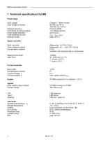
MESA Automation GmbH Input voltage Over voltage protection Chopper frequency Form factor at nominal ratings Power stage protection Fault signalling red LED Braking module Input command Tacho reference signal Compensation network Speed control range static Error Chapter 1.1 Basis models 85 VDC (Ua=60 V) 1.01 (Rated current) short circuit $max , - Imax r Umax correction with potentiometer or components 1:20000 max. output current IAmax Current controller Band width Compensation network Current limitation 1 Current limitation 2 Drive healthy (relay contact) Contact ratings other Data Storage temperature...
Open the catalog to page 4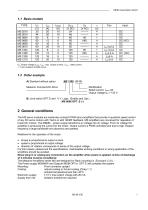
MESA Automation GmbH 1.1 Basis models TYPE UA: Output voltage Uccn ; Imax : max. Output current ; INrms : rated current t : Time constant of RMS circuit A) Standard without option MS 1208 (M 99) Mesanor Compact-DC-Drive Rated current INrms 8A B) Limit switch OPT.E and 0 V Logic (Enable and Opt.) The MS servo modules are extremely compact PWM servo amplifiers that provide 4 quadrant speed control of any DC servo motors with Tacho or with BEMF feedback. MS amplifiers are conceived for regulation of brush DC motors. The MSMN... power supply transforms ac voltage into dc voltage. From dc voltage...
Open the catalog to page 5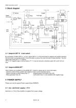
MESA Automation GmbH 3.1 Subprint OPT E Limit switch By connection of GND (OPT E -) or 24 V signal (OPT E +) to the terminals for negative and positive direction the limit switch can be deactivated. If the limit switch is active, the motor will stop in these direction. The limit switch logic level (OPT E += positive, OPT E (-)= negative logic) is set by factory. R 111 must be removed, otherwise option B;C and E will not work. 3.2 Subprint MSM-OPT Other Options are available by using MSM-OPT Subprint- please ask for more information. - external current limiting, positive and negative Output current...
Open the catalog to page 6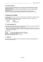
MESA Automation GmbH T ransformers with galvanic separated primary an secondary winding are used for adjustment of supply voltage to the existing net. The Transformers have to correspond to VDE 0550. One and three phase transformers can be used. If the transformer used has a star point in its secondary winding then this should be isolated and NOT connected to earth. A three phase transformer is recommended for current higher than 10 a continuos overall. The factory or your dealer should be consulted to specify the proper size and secondary voltage. The adjustment of Tacho, output current, Irms...
Open the catalog to page 7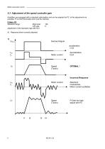
MESA Automation GmbH 5.3 Adjustment of the speed controller gain Amplifiers are equipped with a standard optimisation and can be adapted by P2. Is this adjustment not possible, PI on the Personality card must be checked. P-Gain: P2 Standard range: Right side: Left side: adjustment of the standard rage with R21 A) Response when correctly adjusted Demand Signal acceleration t1;t3 Motor current Speed (Tacho) Motor current Attention! mismatches Motor current oscillates Spees (Tacho) P-Gain too high adjust with P2
Open the catalog to page 8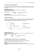
MESA Automation GmbH 5.4 Armature Current Measurement Armature current is measured by means of a shunt placed in series with the armature circuit. The voltage produced can be measured at the „I Monitor“ test point. 10 Volts output corresponds to the maximum current of the amplifier. Max. Output current IAmax: P4 The amplifier is capable of supplying twice is rated current for 1.5-5 seconds. Peak current will be adjusted by P4. Standard-Range: Right side: Left side: IAmax = 1 x Imax = Type-max. current IAmax = 0,03 x I max Current balance: P7 Adjustment of the internal Current measurement! Set...
Open the catalog to page 9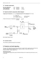
MESA Automation GmbH 5.7 Variable components Set value adjustment: Tacho adjustment: IxR compensation: Standard: Standard: Standard: 5.8 Speed controller components, Block diagram lntegral part C2 Standard: C2 = 0,1 µF Proportional part P2 / R 21 Standard: R21 = 82 kΩ TN = R21 x C2 KNS = R21/R111 x K KN = R21/(P3 + R31) x K K factor is the result of P2 adjustment : Right side: Left side: (command gain) (error gain) Block diagram Speed control 5.9 Current control The controller is optimised by factory do not change ! 6 Protection and fault signalling The green LED indicates the proper function...
Open the catalog to page 10
MESA Automation GmbH Monitoring over voltage If over voltage occurs in the DC Bus voltage, a fault is signalled. Monitoring under voltage The +/- 15 V will drop to 0V DC an disable the amplifier. Monitoring over temperature of the power stage Monitoring of the heat sink temperature up to 90 ° C or 190 ° F • It is Important that the amplifier (Rack or stand-alone) is properly earthed. If the amplifier is not earthed then if an earth fault occurs in the motor circuit the output of the amplifier will be destroyed. • Each motor must be wired separately (cable should be shielded) • Motor cable may...
Open the catalog to page 11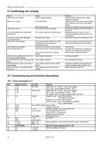
MESA Automation GmbH The motor will not start there is no current supply voltage missing drive not enable Motor wiring open check all fuses are good and supply voltage are present Terminal X1/Pin5 should be connected to 0VDC (optional +24V) for power stage enable check the wiring for the armature circuit An uncontrollably high speed after switching on. The control circuit is polarised The motor is blocked (mechanically) Change the polarity of the tachometer or the motor. Release the brake, if there is one; if necessary dismantle the motor and run no-load test The motor will not start although...
Open the catalog to page 12All Infranor Group catalogs and technical brochures
 XtrapulsPac_EN
4 Pages
 XtrapulsGemTemplates_e_1.4
21 Pages
 XtrapulsGem_User_Manual_v1.2.0.64
199 Pages
 XtrapulsGem_Inst_e_2.1
42 Pages
 XtrapulsGem_Inst_e_2.0
42 Pages
 STO_declaration_Gem
2 Pages
 SMTBSi-2Tz_en_2.1
43 Pages
![SMT100D_e_1.01[1]](https://img.directindustry.com/pdf/repository_di/4620720/smt100d-e-101-1-1141223_1mg.jpg) SMT100D_e_1.01[1]
SMT100D_e_1.01[1]40 Pages
 smt-100
32 Pages
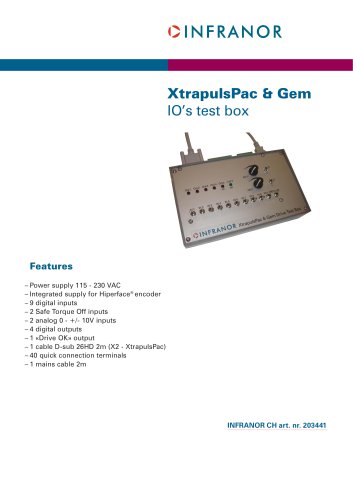 PacSimBox_e
1 Page
 PacSimBox_d_1
1 Page
 Pac-SF01_flyer_en_18.02
4 Pages
 Pac_User_1.2.1.218
253 Pages
 Pac_Templates_en_1.9
27 Pages
 Pac_STO_Installation_en_2.2
13 Pages
 Pac_SF01_operating_en_1.6
63 Pages
 Pac_SF01_EN
4 Pages
 Pac_Installation_en_2.23
82 Pages
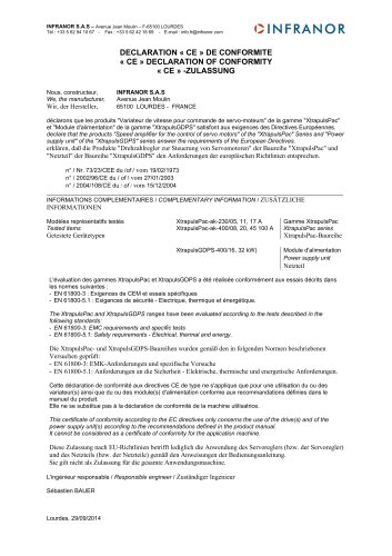 Pac_GDPS_CEconformity
1 Page
 Pac_flyer_en_17.12
4 Pages
 Pac_EC_conformity_25.04
1 Page
 Option_CT_EMF
6 Pages
 MOVINOR_LH055_LH086_LH097_LH142
23 Pages
 ma_series
6 Pages
 GemSafeTorqueOff_en_1.1
12 Pages
 GemProgramming_e_1.1
47 Pages
 GDPS_old_version_1.1_1
11 Pages
 CE_conformity_Gem
1 Page
 CD1pm_e_1.2(old)
18 Pages
 CD1pInst_e_7.2(old)
35 Pages
 CD1kInst_e_4.1(old)
40 Pages
 CD1k_CANopenProtocol_e_1.3(old)
86 Pages
 CD1a_e_7.1(old)
45 Pages
 Catalogue gamme SMT-BD1
11 Pages
 BM20A(F)v3_0
20 Pages
 BM20A(D)v3_0
20 Pages
 BF400(GB)v2_2
21 Pages
 BF400(D)v2_2
21 Pages
 BF230(GB)v2_0
23 Pages
 BF230(F)v2_0
23 Pages
 BD2m_e_2.2
69 Pages
 BD2m(GB)2.0
70 Pages
 BD2_e_3.2
53 Pages
 BD2(GB)3.1
53 Pages
 BD2(D)3.1
54 Pages
 Movinor_LH_e
4 Pages
 ma_series
6 Pages
 BD1t(GB)3.1
81 Pages
 BD1t(F)3.0
85 Pages
 BD1pInst(GB)3.0
25 Pages
 BD1pInst(F)3.0
23 Pages
 BD1pInst(D)3.0
24 Pages
 BD1pCD1pUse_e_2.4
57 Pages
 BD1m(GB)5.0
58 Pages
 BD1m(F)5.0
57 Pages
 BD1m(D)v3_3
64 Pages
 BD1k(GB)2.1
35 Pages
 BD1k(F)2.1
36 Pages
 BD1j(GB)v2_41
19 Pages
 BD1j(F)v2_4
21 Pages
 BD1i(GB)v2_21
23 Pages
 BD1i(F)v2_2
27 Pages
 BD1h(F)3.0
65 Pages
 BD1h(D)3.0
59 Pages
 BD1g(GB)v3_0
28 Pages
 BD1g(F)v3_0
28 Pages
 BD1f(GB)v2_01
18 Pages
 BD1f(F)v2_01
17 Pages
 BD1e(F)v2_01
22 Pages
 BD1d(GB)v2_01
25 Pages
 BD1d(F)v2_01
25 Pages
 BD1c(GB)v2_01
19 Pages
 BD1c(F)v2_01
19 Pages
 BD1a400(GB)v2_3
43 Pages
 BD1a400(F)v2_3
44 Pages
 BD1a400(D)v2_3
45 Pages
 BD1(GB)7.1_noPW
45 Pages
 BD1(GB)7.1
45 Pages
 BD1(F)7.1_noPW
47 Pages
 BD1(F)7.1
47 Pages
 BD1(D)7.1
45 Pages
 BD1 Katalog
11 Pages
 Easy_User_5.0.1.60.2
190 Pages
 08ma_mrm_em_01575
20 Pages
 01ma_smv_e_01953
40 Pages
 PacHP-SF_Flyer_en_23.06
4 Pages
 IRD_User_Manual_en_1.2.XX.54.rev_b
216 Pages
 PacHP_User_en_1.2.8.100.b
280 Pages
 PacHP_TÜV_certificate_25.07
2 Pages
 PacHP_SF02_operating_en_1.6
103 Pages
 PacHP_SF01_operating_en_2.0
63 Pages
 PacHP_Installation_en_2.9
91 Pages
 PacHP_Series_Brochure
8 Pages
 PacHP_Flyer_us_20.10
4 Pages
 IRD_Installation_en_1.5
42 Pages
 IRD_EC_Conformity_25.03
1 Page
 GDPS_Installation_en_4.4
18 Pages
 EtherCAT Interface_en_1.3
20 Pages
 GDPS_EC_conformity_24.07
1 Page
 Easy_STO_en_1.4
14 Pages
 Easy_EC_Conformity_24_10
1 Page
 Easy_DB_STO_en_1.2
14 Pages
 Easy_DB_Installation_en_1.4
36 Pages
 CD1pmUser_en_4.2
55 Pages
 CD1pmInst_en_8.15
40 Pages
 CD1k_CANopenProtocol_en_2.10.1.1
108 Pages
 CD1pm_ProfibusProtocol_en_1.5
50 Pages
 CD1kUser_en_2.3
26 Pages
 CD1a_en_8.17
62 Pages
 CD1kInst_en_5.16
46 Pages
 CD1_STO_en_1.8
16 Pages
 CD1_STO_conformity_19.02
2 Pages
 CD1_flyer_en_14.09
4 Pages
 CD1_EC_conformity_24.05
1 Page
 Braking_Resistors_en_1.5
10 Pages
 AN_DC_bus_interfacing_en_1.3
5 Pages
 AN_CD1pm_SinCosTracks_e_1.0
7 Pages
 AN_CD1pm_AbsoluteEncoder_en_2.0
10 Pages
 AN_CD1ak_SinCosTracks_e_1.0
7 Pages
 AN_CD1ak_AbsoluteEncoder_en_2.0
10 Pages
 XtracontrolDC2_EN
4 Pages
 Flyer_VisiTouchCNC_EN_V1.1-1
2 Pages
 XtraforsWashdown_EN-2024
2 Pages
 DataSheet_CybIO_CNC_V1.0
6 Pages
 XtraforsPrime_EN-2024
2 Pages
 XtraforsMSS_EN
4 Pages
 XtraforsMSA_EN_2024
2 Pages
 XtraforsEx_EN-2024
2 Pages
 XtraforsBR_EN-2024
2 Pages
 XtraforsBL_EN-2024
2 Pages
 XtraforsBC-ed01-vs3
4 Pages
 Manual_XtraforsPrime
46 Pages
 Drawing_1
1 Page
 Datasheet_MSS
5 Pages
 Datasheet_2
2 Pages
 Datasheet_1
4 Pages
 BLSBLT_series
2 Pages
 BL220221
2 Pages
 BL270
BL2702 Pages
 BL190
BL1902 Pages
 bl100_series
6 Pages
 bl40_series
6 Pages
 BL30
BL302 Pages
 2019-01_XtraforsFP-DSL_FR
4 Pages
 Movinor_T_EN
4 Pages
 Movinor_N_EN
4 Pages
 Movinor_Low_Voltage_EN
4 Pages
 Manual Movinor T 03-2026
46 Pages
 Manual Movinor N 03-2026
63 Pages
 XtrapulsEasy™ AC servo-drive
4 Pages
 XtrapulsCD1 AC servo-drives
4 Pages
 CybIO
CybIO6 Pages
 AC SERVOMOTORS
2 Pages
 Movinor® N AC Servomotors
4 Pages