
- Catalogs
- Infranor Group
- 01ma_smv_e_01953


01ma_smv_e_01953

01ma_smv_e_01953
This section underscores the critical importance of safety when handling electronic units in industrial electric power plants. It highlights the risks associated with voltage-carrying parts and mandates that only qualified personnel should operate or work near these machines. Compliance with safety norms such as DIN VDE 0105 or IEC 364 is emphasized.
Guidelines are provided for mounting drives in metallic control cabinets, using shielded lines, and ensuring proper grounding. The section stresses maintaining low impedance and using additional armature chokes if necessary.
In accordance with EC-Directive 2002/06, drives must not be disposed of with general waste.
This section details the specifications for the SMVE/E/N series, including input and output voltages, protection features, and speed control parameters. It lists the types of servo drives available and their power ratings.
The servo modules are designed for rack systems and require adherence to specific regulations for safe operation. Guidance on mounting positions and cooling requirements is provided to ensure optimal performance.
This section describes various functions such as external current limits, integral off functions, and speed command inputs. Options like limit switches and BEMF control are also detailed.
Information on power supply requirements, including mains transformers and auxiliary voltage supplies, is provided.
Guidelines for adjusting potentiometers, resistors, and capacitors are included, along with instructions for setting up speed and current controllers.
Instructions for wiring rack systems and setting up amplifiers are detailed, including offset and speed adjustments.
This section provides troubleshooting tips and solutions for common issues.
Technical specifications, including terminal descriptions, connector details, and test points, are outlined.
Illustrations and examples of mounting schemes and connections are provided to assist with installation.
Details on dimensions, general views, and accessories for power supplies are included.
Additional technical information on specific models is provided.
Warnings and cautions are reiterated to ensure safe handling and operation of the equipment.
The document outlines the specifications for the SMVE/E/N range of amplifiers, emphasizing the importance of maintaining a surrounding temperature not exceeding 45°C. It specifies that connections within the motor power circuit should not be made or interrupted during operation, and connectors on the amplifier should not be plugged or unplugged when power is applied. The electronic supply is internally produced at ±15 V with a maximum charge of 20 mA external, and the mains AC supply is via a transformer with galvanically separated windings.
The SMVE/E/N amplifiers feature a 4-Q-speed controller with internal current control, various control functions, and LED indicators for different signals. The amplifiers are designed for high dynamics, stability, and a wide range of supply voltages. They include options for increased supply voltage and special battery working amplifiers. The document provides a detailed block diagram and functional description of the speed controller, current controller, PWM, and power stage.
The amplifiers offer extended standard functions and additional option boards. Key functions include external current limit, integral off function, second input for speed command, and armature current monitoring. The PLS function allows for monitoring and controlling signals with adjustable delay timers. Various options like limit switches, commutation current limit, ramp generator, and BEMF control are available for customization.
The power supply for the SMVE/N control modules is provided by a transformer with separated windings, adhering to VDE 0550 regulations. The document details the power supply setup for SMVE/E racks and SMVEN drives, including the use of internal power rectifiers and capacitor batteries for braking energy absorption.
The document provides guidance on adjusting and personalizing the controller modules, including potentiometer settings for tacho signal adjustment, proportional gain, and armature current limits. It also covers the use of fixed resistors and capacitors for various adjustments and the personalization plug X10 for integrating variable components.
In case of a fault, the system reacts by stopping the power stage, opening the "ready" relay contact, and providing a warning through LED indications. The fault remains registered until the power voltage is switched off or reset using the reset switch OS 10.
The system features an electronic, fast security circuit with a delay time of approximately 6µs, protecting the power stage even in complete short circuit scenarios. Faults are indicated by LED signals.
Over voltages in the DC power supply are indicated, with reactions similar to other faults.
If the electronic supply voltage drops below ± 12 V, a fault is indicated, but not registered.
A sensor monitors the power stage heat sink temperature, stopping the power stage if it exceeds 90°C. Reset occurs after cooling or fault correction.
If the supply voltage drops below 50 VDC, the power stage is blocked, and signals are activated. Reset occurs when voltage exceeds 50 VDC.
Proper earthing of the amplifier is crucial. Motor cables should be separated from control cables and shielded to reduce electrical noise. Control equipment and amplifiers must operate at the same potential. All control and signal cables should be twisted and shielded in pairs.
The mechanical construction allows for wall or swivel frame mounting. The rack begins with the power supply or controller module, followed by other modules in order of rated current.
Before setup, ensure proper earthing, correct transformer voltage, wiring, and adjustments. Pre-adjust potentiometers if not factory-set.
Disconnect speed demand or 0V indication, switch on the amplifier, and enable it. Adjustments may be needed based on motor behavior.
Adjust the IAmax potentiometer for maximum current output. Use oscillographic methods for precise adjustments.
Adjust speed demand polarity to match rotation direction. Ensure supply voltage and tacho voltage are sufficient.
Adjust P-gain using P2 for stability. Use an oscillograph for optimal adjustment.
Common faults include no motor operation, uneven running, and uncontrolled motor drift. Remedies involve checking supply voltage, wiring, and adjustments.
Details on front connectors, power connectors, solder straps, and test points are provided. Technical data includes choke types and dimensions.
The document outlines various models of power supplies and their specifications, including SMVEE and SMN/W series. Key parameters include inductivity, fuse types, rack sizes, and power supply dimensions. The minimum inductivity in the armature circuit is specified as 1 TE ≈ 0.2".
Details on fuse types and sizes for different models are provided. For example, SMVE/E/N XX models use 1 A F and 10-30 A MT fuses, while SMN/W models use 10 A MT fuses.
Racks are specified according to DIN 41 494, with dimensions provided for various sizes (e.g., SMRS 84). Rack height is consistently 6 HE.
Instructions for mounting schemes and connections for SMVE/E/N control and rack connections are included. Specific contact ratings and minimum cross-sections are noted.
The SMN and SMNW series power supplies are equipped with braking units and internal over-voltage protection. Dimensions and general views of power supplies are detailed, with specific models like SMN07, SMN13, and SMNW07 having distinct electrical characteristics.
Modification instructions for new servo power supplies are provided, including changes in terminal positions and connector pinning. Compatibility with previous models is addressed.
Important safety instructions are summarized, emphasizing the need to calculate braking power before installation and the risks of exceeding limit values.
Information on power resistors and their compatibility with specific power supply types is included.
A comprehensive list of abbreviations and their explanations is provided, covering terms like Imax, UCC, and Pmax.
Contact details for MESA AUTOMATION GmbH and the INFRANOR GROUP are provided for further technical support.
Catalog excerpts
CMESA SERVO-DRIVES & MOTION CONTROL SERVO CONTROLLER SERIES Power Supply SMN/W Operating Manual
Open the catalog to page 1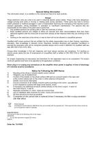
General Safety Information This information sheet is an addition to the manual and has to be read carefully. These electronic units are units to be used in industrial electric power plants. These units have dangerous, voltage-carrying bare parts or moving or rotating parts during operation. These parts may lead to serious health problems or material damages in case of inadmissible removing (for example) of the required covers, inproper application, wrong installation or operation or insufficient maintenance. The persons that are responsable for the safety of the plant have to grant that ■ only...
Open the catalog to page 2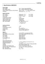
1 Specifications SMVE/E/NPower Stage Input voltage Over voltage control Output chopper frequency and formfactor Protection Input voltage 1 Input voltage 2 Tacho input Compensation network P-gain correction with I-gain correction with Speed control range stat. control default see 1.1 basis models SMVE/E/N see 1.3 basis models power supplies approx. 8 kHz , f = 1.01 (with rated current) sh°rt-circuit, 'O'max , - Tmax ;- Umax potentiometer components 1:20000 (stat.) Compensation network Current limit 1 Current limit 2 Drive signal Signal relay (dry relay contact) Drive signal Over current Over voltage...
Open the catalog to page 5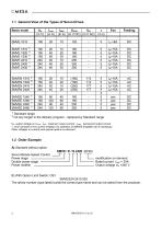
1.1 General View of the Types of Servo Drives 2) not any longer in the delivery program - replaced by Standard range Ua: output voltage on Uccn ; Imax : maximum output current ; Irated : permanent output current t : time constant of rms current imitation, for operation of SMVEE amplifiers fan is necessary Other voltages or currents and special options on demand. A) Standard without option modification on demand Rated current INeff = 20A Output voltage Ua =240 V Servo Module Speed Control Power stage - — Double power stage - - Power rectifier B) With Option Limit Switch: OS1 The article number...
Open the catalog to page 6
2 Principles of Operation The servo modules are designed for rack systems in 6HE sizes . Their application range can be extended by using different options. In order to grant the high reliability of the system and the security of the personal, the following regulations have to be considered: VDE 0100, VDE 0160, part 1 and 2 in relation with VDE 0660, part 5 as well as VDE 0113. For limit values, please look the specifications. Inadmissible working conditions or wrong application of the amplifiers should be avoided. Mounting position: Cooling: Electronic supply: Mains AC supply: front connector...
Open the catalog to page 7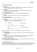
3.2 Functional Description Speed controller fast PI controller, for exact control of motor speed by means of comparison of Speed demand and tacho voltage, produces current demand max. ± 10 V Current controller fast PI controller for exact control of armature current enclosing the whole range of output voltage, produces control voltage for PWM Pulse Width Modulator (PWM) produces logic control signals for the power stage by special modulation technics Power stage MOS-FET, IGBT or bipolar power stage in bridge circuit for low-loss power control Armature current measuring fast measurement of the...
Open the catalog to page 9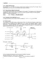
3.3.2 Integral Off Function By applying 0 V on X7 / PIN 10 the speed controller will be switched over from PI to P-mode. Thus a higher stability and a lower drift can be reached under certain conditions. 3.3.3 Second Input (Speed Command) Two equivalent speed demand inputs are available on the amplifier. The weighting can be influenced by changing R111 input 1 and R112 input 2. With the two inputs a big speed range can be easy adjusted. Speed is relatively low, for example: Input 1 10 V = 3000 rpm ⇒ high speed operation Input 2 10 V = 300 rpm ⇒ low speed operation 3.3.4 Armature Current Monitor...
Open the catalog to page 10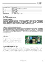
Further option boards are available. The limit switches become inactive when connecting 0 V. If the input remains open, the negative and/or positive speed demand will be blocked. The logic level is fixed by factory and cannot be changed, standard: negative logic. On operation of the limit switch the motor stops in the given direction with a maximum adjusted IAmax. Caution: do not connect voltage on the limit switch inputs! With certain motor types it becomes necessary to limit the armature current by high speed. By means of the armature voltage measuring and a plug module (X1) corresponding to...
Open the catalog to page 11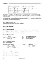
Ramp time constant in s/V Pot. R8 A jump of set value of 0 V to 10 V will be transformed in a 0,03 s long ramp. Asymmetrical relations of positive and negative ramp can be set by using R3 (positive ramp) and/or R4 (negative ramp) according to the above table. The values are valid for Options without C2 fur standard placement of R111 and R112 on the logic board. The ramp time can be prolongated by using C2. This option is for speed control without tacho - generator. The motor speed can be set by potentiometer R11. By extending R111 set value input 1 or R112 set value input 2 (both on the logic...
Open the catalog to page 12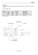
• Plug the Option board only in powerless mode ! The Pot. R8 and R11 are oriented to connector X7 andX8. • Select operating mode : Option - Board for SMVE, SMVEE for SMVEN
Open the catalog to page 13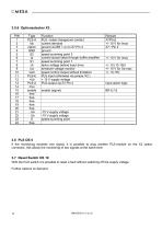
If the monitoring exceeds one signal, it is possible to plug another PLS-module on the X3 option connector, this allows the monitoring of two signals at the same time. With the front switch it is possible to reset a fault without switching off the supply voltage. Further options on demand.
Open the catalog to page 14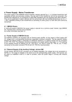
4 Power Supply - Mains Transformer The power supply of the SMVE/N control modules is always assured by a 1- or 3-phase transformer with separated primary and secondary winding. The star point of the transformer will not be connected. The transformers delivered by us correspond to VDE 0550 regulations and are equipped with IP00 protection. They can be applicated in switch cabinets with the same power with surrounding temperatures up to ϑu = + 40°C. Standard winding of the transformers is according to vector group YY0 (the star point cannot be connected). 4.1 SMVE/E Racks In multi-unit-systems...
Open the catalog to page 15All Infranor Group catalogs and technical brochures
 XtrapulsPac_EN
4 Pages
 SMTBSi-2Tz_en_2.1
43 Pages
 PacSimBox_d_1
1 Page
 Pac-SF01_flyer_en_18.02
4 Pages
 Pac_User_1.2.1.218
253 Pages
 Pac_Templates_en_1.9
27 Pages
 Pac_STO_Installation_en_2.2
13 Pages
 Pac_SF01_operating_en_1.6
63 Pages
 Pac_SF01_EN
4 Pages
 Pac_Installation_en_2.23
82 Pages
 Pac_flyer_en_17.12
4 Pages
 Option_CT_EMF
6 Pages
 MOVINOR_LH055_LH086_LH097_LH142
23 Pages
 ma_series
6 Pages
 GemSafeTorqueOff_en_1.1
12 Pages
 CD1pm_e_1.2(old)
18 Pages
 CD1pInst_e_7.2(old)
35 Pages
 CD1kInst_e_4.1(old)
40 Pages
 CD1k_CANopenProtocol_e_1.3(old)
86 Pages
 CD1a_e_7.1(old)
45 Pages
 Catalogue gamme SMT-BD1
11 Pages
 BM20A(F)v3_0
20 Pages
 BM20A(D)v3_0
20 Pages
 BF400(GB)v2_2
21 Pages
 BF400(D)v2_2
21 Pages
 BF230(GB)v2_0
23 Pages
 BF230(F)v2_0
23 Pages
 BD2m_e_2.2
69 Pages
 BD2m(GB)2.0
70 Pages
 BD2_e_3.2
53 Pages
 BD2(GB)3.1
53 Pages
 BD2(D)3.1
54 Pages
 Movinor_LH_e
4 Pages
 ma_series
6 Pages
 BD1t(GB)3.1
81 Pages
 BD1t(F)3.0
85 Pages
 BD1pInst(GB)3.0
25 Pages
 BD1pInst(F)3.0
23 Pages
 BD1pInst(D)3.0
24 Pages
 BD1pCD1pUse_e_2.4
57 Pages
 BD1m(GB)5.0
58 Pages
 BD1m(F)5.0
57 Pages
 BD1m(D)v3_3
64 Pages
 BD1k(GB)2.1
35 Pages
 BD1k(F)2.1
36 Pages
 BD1j(GB)v2_41
19 Pages
 BD1j(F)v2_4
21 Pages
 BD1i(GB)v2_21
23 Pages
 BD1i(F)v2_2
27 Pages
 BD1h(F)3.0
65 Pages
 BD1h(D)3.0
59 Pages
 BD1g(GB)v3_0
28 Pages
 BD1g(F)v3_0
28 Pages
 BD1a400(GB)v2_3
43 Pages
 BD1a400(F)v2_3
44 Pages
 BD1a400(D)v2_3
45 Pages
 BD1(GB)7.1_noPW
45 Pages
 BD1(GB)7.1
45 Pages
 BD1(F)7.1_noPW
47 Pages
 BD1(F)7.1
47 Pages
 BD1(D)7.1
45 Pages
 BD1 Katalog
11 Pages
 Easy_User_5.0.1.60.2
190 Pages
 PacHP-SF_Flyer_en_23.06
4 Pages
 IRD_User_Manual_en_1.2.XX.54.rev_b
216 Pages
 PacHP_User_en_1.2.8.100.b
280 Pages
 PacHP_SF02_operating_en_1.6
103 Pages
 PacHP_SF01_operating_en_2.0
63 Pages
 PacHP_Installation_en_2.9
91 Pages
 PacHP_Series_Brochure
8 Pages
 PacHP_Flyer_us_20.10
4 Pages
 IRD_Installation_en_1.5
42 Pages
 Easy_STO_en_1.4
14 Pages
 Easy_DB_STO_en_1.2
14 Pages
 Easy_DB_Installation_en_1.4
36 Pages
 CD1pmUser_en_4.2
55 Pages
 CD1pmInst_en_8.15
40 Pages
 CD1k_CANopenProtocol_en_2.10.1.1
108 Pages
 CD1pm_ProfibusProtocol_en_1.5
50 Pages
 CD1kUser_en_2.3
26 Pages
 CD1a_en_8.17
62 Pages
 CD1kInst_en_5.16
46 Pages
 CD1_STO_en_1.8
16 Pages
 CD1_flyer_en_14.09
4 Pages
 Braking_Resistors_en_1.5
10 Pages
 XtracontrolDC2_EN
4 Pages
 Flyer_VisiTouchCNC_EN_V1.1-1
2 Pages
 XtraforsWashdown_EN-2024
2 Pages
 DataSheet_CybIO_CNC_V1.0
6 Pages
 XtraforsPrime_EN-2024
2 Pages
 XtraforsMSS_EN
4 Pages
 XtraforsMSA_EN_2024
2 Pages
 XtraforsEx_EN-2024
2 Pages
 XtraforsBR_EN-2024
2 Pages
 XtraforsBL_EN-2024
2 Pages
 XtraforsBC-ed01-vs3
4 Pages
 Manual_XtraforsPrime
46 Pages
 Drawing_1
1 Page
 Datasheet_MSS
5 Pages
 Datasheet_2
2 Pages
 Datasheet_1
4 Pages
 BLSBLT_series
2 Pages
 BL220221
2 Pages
 BL270
BL2702 Pages
 BL190
BL1902 Pages
 bl100_series
6 Pages
 bl40_series
6 Pages
 BL30
BL302 Pages
 2019-01_XtraforsFP-DSL_FR
4 Pages
 Movinor_T_EN
4 Pages
 Movinor_N_EN
4 Pages
 Movinor_Low_Voltage_EN
4 Pages
 Manual Movinor T 03-2026
46 Pages
 Manual Movinor N 03-2026
63 Pages
 XtrapulsEasy™ AC servo-drive
4 Pages
 XtrapulsCD1 AC servo-drives
4 Pages
 CybIO
CybIO6 Pages
 AC SERVOMOTORS
2 Pages
 Movinor® N AC Servomotors
4 Pages






Archived catalogs
 AN_CD1ak_AbsoluteEncoder_en_2.0
10 Pages
 AN_CD1ak_SinCosTracks_e_1.0
7 Pages
 AN_CD1pm_AbsoluteEncoder_en_2.0
10 Pages
 AN_CD1pm_SinCosTracks_e_1.0
7 Pages
 AN_DC_bus_interfacing_en_1.3
5 Pages
 CD1_EC_conformity_24.05
1 Page
 CD1_STO_conformity_19.02
2 Pages
 EtherCAT Interface_en_1.3
20 Pages
 Easy_EC_Conformity_24_10
1 Page
 GDPS_EC_conformity_24.07
1 Page
 IRD_EC_Conformity_25.03
1 Page
 PacHP_TÜV_certificate_25.07
2 Pages
 BD1c(F)v2_01
19 Pages
 BD1c(GB)v2_01
19 Pages
 BD1d(F)v2_01
25 Pages
 BD1d(GB)v2_01
25 Pages
 BD1e(F)v2_01
22 Pages
 BD1f(F)v2_01
17 Pages
 BD1f(GB)v2_01
18 Pages
 Pac_EC_conformity_25.04
1 Page




















