- Catalogs
- Infineon Technologies AG
- IPP60R160P7
- Products
- Catalogs
- News & Trends
- Exhibitions
IPP60R160P7
1 /14Pages

IPP60R160P7
1 /14Pages
Catalog excerpts

MOSFET 600V CoolMOS™ P7 PowerTransistor The CoolMOS™ 7th generation platform is a revolutionary technology for high voltage power MOSFETs, designed according to the superjunction (SJ) principle and pioneered by Infineon Technologies. The 600V CoolMOS™ P7 series is the successor to the CoolMOS™ P6 series. It combines the benefits of a fast switching SJ MOSFET with excellent ease of use, e.g. very low ringing tendency, outstanding robustness of body diode against hard commutation and excellent ESD capability. Furthermore, extremely low switching and conduction losses make switching applications even more efficient, more compact and much cooler. Features • Suitable for hard and soft switching (PFC and LLC) due to an outstanding commutation ruggedness • Significant reduction of switching and conduction losses • Excellent ESD robustness >2kV (HBM) for all products • Better RDS(on)/package products compared to competition enabled by a low RDS(on)*A (below 1Ohm*mm2) Benefits • Ease of use and fast design-in through low ringing tendency and usage across PFC and PWM stages • Simplified thermal management due to low switching and conduction losses • Increased power density solutions enabled by using products with smaller footprint and higher manufacturing quality due to >2 kV ESD protection • Suitable for a wide variety of applications and power ranges Potential applications PFC stages, hard switching PWM stages and resonant switching stages for e.g. PC Silverbox, Adapter, LCD & PDP TV, Lighting, Server, Telecom and UPS. Product validation Fully qualified according to JEDEC for Industrial Applications Please note: For MOSFET paralleling the use of ferrite beads on the gate or separate totem poles is generally recommended. Table 1 Key Performance Parameters Final Data Sheet
Open the catalog to page 1
TableofContents Description . . . . . . . . . . . . . . . . . . . . . . . . . . . . . . . . . . . . . . . . . . . . . . . . . . . . . . . . . . . . . . . . . . . . . . . . . . . . . 1 Maximum ratings . . . . . . . . . . . . . . . . . . . . . . . . . . . . . . . . . . . . . . . . . . . . . . . . . . . . . . . . . . . . . . . . . . . . . . . . 3 Thermal characteristics . . . . . . . . . . . . . . . . . . . . . . . . . . . . . . . . . . . . . . . . . . . . . . . . . . . . . . . . . . . . . . . . . . . . 4 Electrical characteristics . . . . . . . . . . . . . . . . . . . . . . . . . . . . . . . ....
Open the catalog to page 2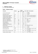
at T = 25°C, unless otherwise specified Table 2 Maximum ratings 11 Limited by Tj,max. Maximum Duty Cycle D = 0.50 2) Pulse width tp limited by Tj, 3) Identical low side and high side switch with identical Rg Final Data Sheet 3 Rev. 2.0, 2019-02-26
Open the catalog to page 3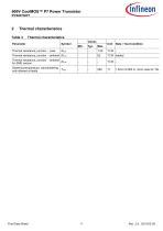
Table 3 Thermal characteristics Final Data Sheet
Open the catalog to page 4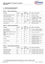
at 7j=25°C, unless otherwise specified Table 4 Static characteristics 11 Co(er) is a fixed capacitance that gives the same stored energy as C0ss while VDs is rising from 0 to 400V 2) Co(tr) is a fixed capacitance that gives the same charging time as Coss while VDs is rising from 0 to 400V Final Data Sheet 5 Rev. 2.0, 2019-02-26
Open the catalog to page 5
Table 7 Reverse diode characteristics Final Data Sheet
Open the catalog to page 6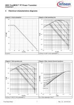
single pulse Final Data Sheet
Open the catalog to page 7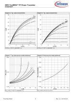
600V CoolMOS™ P7 PowerTransistorIPP60R160P7Diagram 5: Typ. output characteristicsDiagram 6: Typ. output characteristics 60 Diagram 7: Typ. drain-source on-state resistanceDiagram 8: Drain-source on-state resistance Final Data Sheet Rev. 2.0, 2019-02-26
Open the catalog to page 8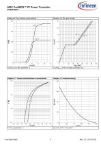
Diagram 9: Typ. transfer characteristics Diagram 10: Typ. gate charge Vss=f( Qgate); /d=6.3 A pulsed; parameter: Vdd Diagram 11: Forward characteristics of reverse diode Diagram 12: Avalanche energy Final Data Sheet Rev. 2.0, 2019-02-26
Open the catalog to page 9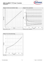
Final Data Sheet 10
Open the catalog to page 10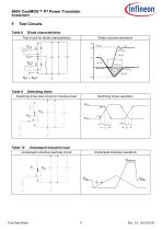
5TestCircuits Table8Diodecharacteristics Test circuit for diode characteristics Diode recovery waveform Table9Switchingtimes Switching times test circuit for inductive load Switching times waveform VDS Table10Unclampedinductiveload Unclamped inductive load test circuit Unclamped inductive waveform Final Data Sheet
Open the catalog to page 11
Final Data Sheet
Open the catalog to page 12
7 Appendix A Table 11 Related Links • IFX CoolMOS P7 Webpage: www.infineon.com • IFX CoolMOS P7 application note: www.infineon.com • IFX CoolMOS P7 simulation model: www.infineon.com • IFX Design tools: www.infineon.com Final Data Sheet
Open the catalog to page 13
Trademarks All referenced product or service names and trademarks are the property of their respective owners. We Listen to Your Comments Any information within this document that you feel is wrong, unclear or missing at all? Your feedback will help us to continuously improve the quality of this document. Please send your proposal (including a reference to this document) to: [email protected] Published by Infineon Technologies AG 81726 Munchen, Germany © 2018 Infineon Technologies AG All Rights Reserved. Legal Disclaimer The information given in this document shall in no event be regarded...
Open the catalog to page 14All Infineon Technologies AG catalogs and technical brochures
 IPB60R045P7
14 Pages
 IPD900P06NM
10 Pages
 Every switch needs a driver
10 Pages
 CoolMOS™ 7 - CoolSiC™ - CoolGaN™
28 Pages
 IPAN60R360P7S
14 Pages
 IPAN60R180P7S
14 Pages
 IPZA60R045P7
14 Pages
 BSZ063N04LS6
11 Pages
 BAW78.../BAW79...
6 Pages
 Automotive Power Selection Guide
114 Pages
 Custom Made Blanking Line
9 Pages
 XC800 Family
54 Pages
 IFBIP-Company-Brochure
11 Pages
 Shortform Catalog 2013
212 Pages
 Efficient Lighting Brochure 2013
24 Pages
 Industrial Automation Brochure
52 Pages
 Transceiver Brochure
16 Pages
 Automotive Application Guide
54 Pages
 ESD/Surge Protection Diodes
43 Pages
 IGBT Selection Guide
6 Pages
 Payment
5 Pages
 Absolute Pressure Sensor
24 Pages
 Schottky Diodes
7 Pages
 Silicon Switching Diode
6 Pages
 Dual Ic
8 Pages
 PrimePACK™ IGBT Modules
2 Pages


Archived catalogs
 Linear Voltage Regulators
17 Pages
 ModSTACK™ HD
2 Pages
 8-Bit Microcontrollers
20 Pages
 Sense & Control Selection Guide
24 Pages
 Communication Brochure
8 Pages
 COM Image Brochure
12 Pages


- AMOT power supply
- AMOT DC power supply
- AMOT AC/DC power supply
- Switching power supply
- DC-DC converter
- Regulated power supply
- AMOT transistor
- Industrial DC/DC converter module
- SMD DC-DC converter
- AMOT magnetic sensor
- Open frame power supply
- AMOT switching transistor
- CE DC/DC converter module
- AMOT MOSFET transistor
- Current rectifier
- Bipolar transistor
- AMOT microcontroller
- Switching DC-DC converter
- Hall effect magnetic sensor
- Development kit