- Catalogs
- Infineon Technologies AG
- Absolute Pressure Sensor
- Products
- Catalogs
- News & Trends
- Exhibitions
Absolute Pressure Sensor
1 /24Pages

Absolute Pressure Sensor
1 /24Pages
Catalog excerpts

November 2007 Sense & Control Data Sheet Rev 1.02 Absolute Pressure Sensor KP124
Open the catalog to page 1
Edition 2007-11-23 Published by Infineon Technologies AG 81726 München, Germany © 2007 Infineon Technologies AG All Rights Reserved. Legal Disclaimer The information given in this document shall in no event be regarded as a guarantee of conditions or characteristics. With respect to any examples or hints given herein, any typical values stated herein and/or any information regarding the application of the device, Infineon Technologies hereby disclaims any and all warranties and liabilities of any kind, including without limitation, warranties of non-infringement of intellectual property rights...
Open the catalog to page 2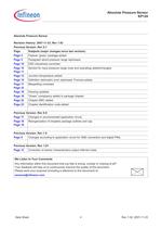
Data Sheet 4 Rev 1.02, 2007-11-23 Absolute Pressure Sensor KP124 Absolute Pressure Sensor Revision History: 2007-11-23, Rev 1.02 Previous Version: Rev 0.1 Page Subjects (major changes since last revision) Page 5 Feature “green” package added. Page 5 Paragraph about pressure range rephrased. Page 10 ESD robustness corrected. Page 10 Page 11 Symbol for input pressure range (max and operating) added/changed. Page 12 Junction temperature added. Page 15 Definition ratiometric error rephrased. Formula added. Page 17 Page 23 Misspelling corrected. Page 19 Drawing updated. Page 19 “Green” compliancy...
Open the catalog to page 4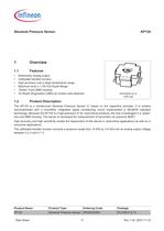
PG-DSOF-8-12 with cap Product Name Product Type Ordering Code Package KP124 Absolute Pressure Sensor SP000239581 PG-DSOF-8-12 Data Sheet 5 Rev 1.02, 2007-11-23 Absolute Pressure Sensor KP124 1Overview 1.1Features •Ratiometric analog output •Calibrated transfer function •High accuracy over a large temperature range •Maximum error ± 1.5% Full Scale Range •“Green” 8-pin SMD housing •On Board Diagnostics (OBD) for broken wire detection 1.2Product Description The KP124 is a miniaturized Absolute Pressure Sensor IC based on the capacitive principle. It is surface micromachined with a monolithic integrated...
Open the catalog to page 5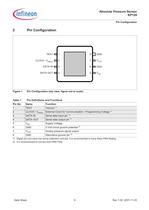
Data Sheet 6 Rev 1.02, 2007-11-23 Absolute Pressure Sensor KP124 Pin Configuration 2Pin Configuration Figure 1Pin Configuration (top view, figure not to scale) Table 1Pin Definitions and Functions Pin No. Name Function 1 TEST Test pin 1) 1)Digital pins are used only during calibration and test. It is recommended to leave these PINs floating. 2 CLOCK / VPROG External Clock for Communication / Programming Voltage 1) 3 DATA IN Serial data input pin 1) 4 DATA OUT Serial data output pin 1) 5 VDD Supply Voltage 6 GND 0 Volt circuit ground potential 2) 2)It is recommended to connect both GND PINs. 7...
Open the catalog to page 6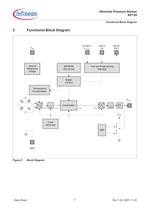
Data Sheet 7 Rev 1.02, 2007-11-23 Absolute Pressure Sensor KP124 Functional Block Diagram 3Functional Block Diagram Figure 2Block Diagram AD1 bitDA12 bit10 bit1 kHzLinearizationOBDVDDClockGeneratorTemperatureCompensationInternalReferenceVoltageEEPROM(90+22 bit)DigitalControlTest and ProgrammingInterfaceVDDCLOCK /VPROGDATAINGNDDATAOUTVOUT30kHz10 bit
Open the catalog to page 7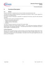
Data Sheet 8 Rev 1.02, 2007-11-23 Absolute Pressure Sensor KP124 Functional Description 4Functional Description 4.1Sensor Pressure is detected in a capacitive way by an array of surface micromachined sensor cells. The sensor cell output is amplified, temperature compensated and linearized to obtain an output voltage that is proportional to the applied pressure. The transfer function for linearization is calculated in the digital part of the sensor using third order polynomial calculation. The transfer function is given by the following parameters: •Minimum and maximum rated pressure •Voltage...
Open the catalog to page 8
Data Sheet 9 Rev 1.02, 2007-11-23 Absolute Pressure Sensor KP124 Functional Description 4.2Transfer Function The KP124 device is fully calibrated on delivery. The sensor has a linear transfer function between the applied pressure and the output signal: The output is ratiometric. Gain a and Offset b are determined during calibration in order to create the required transfer function. Standard Transfer Function The following calibration is adjusted with the parameters a and b: Figure 3Transfer Function Note:The application circuitry determines the current driven by the device and thus has an impact...
Open the catalog to page 9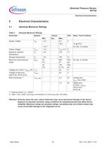
Data Sheet 10 Rev 1.02, 2007-11-23 Absolute Pressure Sensor KP124 Electrical Characteristics 5Electrical Characteristics 5.1Absolute Maximum Ratings Attention:Stresses above the max. values listed here may cause permanent damage to the device. Exposure to absolute maximum rating conditions for extended periods may affect device reliability. Maximum ratings are absolute ratings; exceeding only one of these values may cause irreversible damage to the integrated circuit. Table 3Absolute Maximum Ratings Parameter Symbol Values Unit Note / Test Condition Min. Typ. Max. Supply voltage VDD – 0.3 – 6.5...
Open the catalog to page 10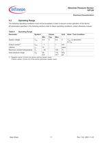
Data Sheet 11 Rev 1.02, 2007-11-23 Absolute Pressure Sensor KP124 Electrical Characteristics 5.2Operating Range The following operating conditions must not be exceeded in order to ensure correct operation of the device. All parameters specified in the following sections refer to these operating conditions, unless otherwise noticed. Table 4Operating Range Parameter Symbol Values Unit Note / Test Condition Min. Typ. Max. Supply voltage VDD 4.5 5 5.5 V VOUT is ratiometric to VDD Output current1) 1)Negative values: Current into device (pull-up resistor used). Positive values: Current out of the device...
Open the catalog to page 11
Data Sheet 12 Rev 1.02, 2007-11-23 Absolute Pressure Sensor KP124 Electrical Characteristics 5.3Sensor Characteristics Table 5Sensor Characteristics Parameter Symbol Values Unit Note / Test Condition Min. Typ. Max. Output Voltage Range VOUT_R 0.10 4.85 V More information in chapter “Electrical Details” on Page 13 Sensitivity S – 45 – mV/ kPa Supply current IDD – 8 10 mA 1) 1)A peak supply current of up to 22 mA is possible during power up. Overall Accuracy Error Err – – ± 1.5 % FSS (Full Scale Span) 2) 2)More details in chapter “Overall Accuracy” on Page 16 Ratiometric Error ERAT –25 – 25 mV...
Open the catalog to page 12All Infineon Technologies AG catalogs and technical brochures
 IPB60R045P7
14 Pages
 IPD900P06NM
10 Pages
 Every switch needs a driver
10 Pages
 CoolMOS™ 7 - CoolSiC™ - CoolGaN™
28 Pages
 IPAN60R360P7S
14 Pages
 IPAN60R180P7S
14 Pages
 IPP60R160P7
14 Pages
 IPZA60R045P7
14 Pages
 BSZ063N04LS6
11 Pages
 BAW78.../BAW79...
6 Pages
 Automotive Power Selection Guide
114 Pages
 Custom Made Blanking Line
9 Pages
 XC800 Family
54 Pages
 IFBIP-Company-Brochure
11 Pages
 Shortform Catalog 2013
212 Pages
 Efficient Lighting Brochure 2013
24 Pages
 Industrial Automation Brochure
52 Pages
 Transceiver Brochure
16 Pages
 Automotive Application Guide
54 Pages
 ESD/Surge Protection Diodes
43 Pages
 IGBT Selection Guide
6 Pages
 Payment
5 Pages
 Schottky Diodes
7 Pages
 Silicon Switching Diode
6 Pages
 Dual Ic
8 Pages
 PrimePACK™ IGBT Modules
2 Pages


Archived catalogs
 Linear Voltage Regulators
17 Pages
 ModSTACK™ HD
2 Pages
 8-Bit Microcontrollers
20 Pages
 Sense & Control Selection Guide
24 Pages
 Communication Brochure
8 Pages
 COM Image Brochure
12 Pages


- Power supply unit
- DC power supply
- AC/DC power supply
- Switching power supply
- Single-output power supply
- DC-DC converter
- Regulated power supply
- Infineon transistor
- Industrial DC/DC converter module
- SMD DC-DC converter
- Open frame power supply
- Infineon switching transistor
- CE DC/DC converter module
- Infineon MOSFET transistor
- Current rectifier
- Bipolar transistor
- Microcontroller
- Switching DC-DC converter
- Development kit
- Industrial AC/DC converter