
- Catalogs
- Inductoheat Europe GmbH
- ENERGY MONITOR

ENERGY MONITOR

ENERGY MONITOR
- Verification of energy measurements for every machine, reducing the need for destructive testing.
- Can be used as stand-alone or integrated monitors for both new and existing equipment.
- Includes auxiliary contacts for alarms or part rejection.
- Compatible with most control circuits, including control relays, PLCs, and computers.
- Features an easy-to-read digital display for precise energy measurement.
- Universal compatibility, capable of monitoring from 60Hz to 450kHz on any induction heating system.
- Utilizes fiber optic technology to eliminate noise problems.
The energy monitor is designed to meet quality control process requirements by measuring and displaying the actual energy delivered to the heating coil in kilowatt-seconds. It helps ensure that the correct amount of power and heat time are applied, with annunciator lights indicating if the energy is within acceptable limits or if it is insufficient or excessive.
The energy monitor can function as an induction process controller, automatically turning off the power when the desired energy level is reached, which is particularly useful in static heating applications.
The monitor's sensitive circuitry accurately measures and displays the power supply's output, ensuring process requirements are met. Large LED readouts display kilowatt-seconds, and an optional panel-mounted printer is available.
Fiber optics allow for safe and accurate monitoring of the output, eliminating variable conditions between input and output.
- Enclosure Size: 10”W x 8.5”H x 6”D
- Count Range: 0 - 99,999
- Character Size: Machine or panel mounted
- Mounting: Isolated form C; for lower limit, upper limit, and reject
- Reject Reset: Key resettable or interlock
- Operator Voltage: 110/120 V AC, 50/60Hz, 1 A
- Optional Outputs: 0-10 V, 4-20 mA, digital BCD
The energy monitor uses a "No Noise" fiber optics communications link to convert power level measurements into light pulses, ensuring safety and reliability. The fiber optic signal is digitally calibrated and can be displayed on the front panel or stored for communication with PLC systems. Outputs are available for use with PLC systems or stand-alone energy monitors.
Catalog excerpts
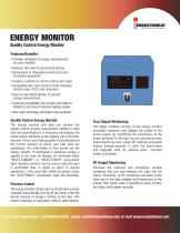
ENERGY MONITOR Quality Control Energy Monitor Features/Benefits: • Provides verification of energy measurements for every machine • Reduces the need for destructive testing • Stand-alone or integrated monitors for new & existing equipment • Auxiliary contacts for alarms and/or part reject • Compatible with most control circuits including control relays, PLC’s and computers • Easy to read digital display of precise energy measurement • Universal compatibility. Can monitor from 60Hz to 450kHz on any type of induction heating system • Fiber optic technology eliminates noise problems Quality Control Energy Monitor The energy monitor will help you achieve the quality control process requirements needed to meet strict part specifications. It measures and displays the actual energy delivered to the heating coil in kilowattseconds. Once a part heating pattern is developed and the correct amount of power and heat time are established, this information is then preset into the energy monitor. If insufficient or excessive energy is applied to the load the display will illuminate either “REJECT/UNDER” or “REJECT/OVER” annunciator light. Auxiliary contacts can be used to reject the part in automated lines or signal an alarm in manual operations. If the count falls within the preset range, the “ACCEPTABLE” annunciator light will illuminate. Process Control The energy monitor can be used as an induction process controller automatically turning off the power when the desired amount of energy is deliver to the load. This mode of operation is particularly useful in static heating. True Output Monitoring The highly sensitive circuitry of the energy monitor accurately measures and displays the output of the power supply. By monitoring the consistency of the power delivered to the load, you are assured process requirements are met. Large LED readouts accurately display kilowatt-seconds in both the stand-alone and integrated units. An optional panel mounted printer is available. RF Output Monitoring Eliminate the unknown and sometimes variable conditions that can exist between the input and the output. Previously, all RF monitoring was done on the input due to the high voltages and frequencies on the output. Fiber optics make it possible to safely monitor the output with greater accuracy. For more information, call 800/624-6297, email: [email protected] or visit www.inductoheat.com
Open the catalog to page 1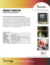
An tnductotherm Croup Company ENERGY MONITOR Quality Control Energy Monitor Safe, "No Noise" Fiber Optics Communications Link Power level measurements are converted into light pulses sending a signal to the energy monitor board. The fiber optics give complete isolation from the high voltage output of the power supply, insuring safety and reliability. The fiber optic signal reciever by the interface board is digitally calibrated for actual kilowatt-seconds. This is displayed directly on the front panel or can be stored in a digital register for communication with PLC systems. The fiber optic signal...
Open the catalog to page 2All Inductoheat Europe GmbH catalogs and technical brochures
 INDUCTOSCAN Move
2 Pages
 Inductoforge™
4 Pages
 IROSS
IROSS2 Pages
 Inductoheat Europe Imagebrochure
20 Pages
 Unicool
1 Page
 Water Recirculating System
2 Pages
 INSTA CHANGE
1 Page
 Load Frequency Analyzer
1 Page
 Large to Medium Bearing Race
2 Pages
 STATISCAN II and IV
2 Pages
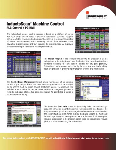 InductoScan PC HMI-PLC
2 Pages
 STATIPOWER®SP18
2 Pages
 STATIPOWER® SP16
2 Pages
 STATIPOWER® SP11
2 Pages
 STATIPOWER® SP12
2 Pages
 STATIPOWER® SP5 & 7
2 Pages
 iRoss
iRoss2 Pages
 STATISCAN®
2 Pages
 UNISCAN® II
2 Pages
 VSM-95
2 Pages


