- Catalogs
- IMO Precision Controls Limited
- i 3 C Mini Intelligent Control Station
i 3 C Mini Intelligent Control Station
1 /4Pages

i 3 C Mini Intelligent Control Station
1 /4Pages
Catalog excerpts
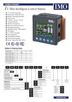
■ 3.5” TFT Colour Touchscreen ■ 65,535 Colours, QVGA (320 x 240) ■ MicroSD™ Data storage upto 32GB ■ Real Time Clock ■ 1 CAN Port, 1 RS-232, 1 RS-485 ■ 1 Integral Ethernet Port ■ USB Port for Programming ■ USB Port for Flash Drives upto 2TB ■ Addressable function keys ■ 1MB RAM (Program), 27MB (Graphical) ■ IP65 (NEMA4) ■ 10 - 30 VDC Power Supply ■ Online Programming ■ Free Configuration Software ■ Remote I/O Communication ■ Optional - Modem (SMS, GSM, GPRS) C € ® c® pg Standard Options * Universal Analogue Inputs
Open the catalog to page 1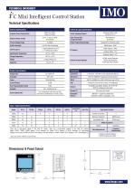
TECHNICAL DATASHEET There are 4 high-speed inputs of the total DC inputs. There are 2 high-speed outputs of the total DC outputs. Model 10D03, 10B04, 20B05 feature 12-bit Analogue I/O. Model 13C14 features 14/16-bit Analogue I/O. High-speed outputs can be used for PWM and Pulse Train Outputs, currently limited to <65kHz. Model 10E14 features a 14/17 bit Analogue I/O. *Up to six mA/V In, RTD/TC, and mA/V Out Pulse Measurement Frequency Measurement 2 Position Controlled Outputs 1 ON/OFF Setpoint per Output Dimensions & Panel Cutout CUTOUT TOLERANCE TO MEET NEMA STANDARDS IS ±0.005” (0.1mm) Max....
Open the catalog to page 2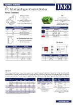
DC Input / Frame Torque rating: 4.5-7 Lb-in (0.50-0.78Nm) DC- is internally connected to I/O V-, but is isolated from CAN VA Class 2 power supply must be used CAN Locking Spring-Clamp 2-Terminators Per Conductor Mounting screw torque rating: 4.5 Lb-in (0.50Nm) SHLD and V+ pins are not internally connected to i3C Mini Primary Power Port Pins Primary Power Port Pins 2 DC- Input Power Supply Ground 3 DC+ Input Power Supply Voltage Signal Description Direction V- CAN Ground - Black - CN L CAN Data Low - Blue IN / OUT SHLD Shield Ground - None - CAN Data High -...
Open the catalog to page 3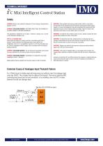
WARNING: Battery may explode if mistreated. Do not recharge, disassemble or dispose of in fire. WARNING: EXPLOSION HAZARD - BATTERIES MUST ONLY BE CHANGED IN AN AREA KNOWN TO BE NON-HAZARDOUS This equipment is suitable for use in Class 1, Division 2, Groups A, B, C and D or Non-hazardous locations only. FOR U.S. & CANADA ONLY Power input and output (I/O) wiring must be in accordance with Class 1, Division 2 wiring methods of the National Electric Code, NFPA70 for installations in the U.S. or as specified in Section 18-1J2 of the Canadian Electric Code for installations within Canada and in accordance...
Open the catalog to page 4All IMO Precision Controls Limited catalogs and technical brochures
 IMO Corporate Brochure
9 Pages
 SolarProduct Range
56 Pages
 Drive 2
6 Pages
 Industrial Power Supplies Range
28 Pages
 Inductive Proximity Switches PB
10 Pages
 VXA Brochure
12 Pages
 Push Buttons
32 Pages
 MCB Brochure
8 Pages
 Din Terminals
64 Pages
 Panel Products
24 Pages
 Solar Installer
12 Pages
 Solar Isolators
32 Pages
 Self Funding Scheme
12 Pages
 HVAC Brochure
12 Pages
 Jaguar Drives
20 Pages
 Terminal Block
68 Pages
 Relays
36 Pages
 Audible Devices
126 Pages
 Solar Cube
4 Pages
 i3 Intelligent Controllers
8 Pages
 BX series
3 Pages
 Remote IO Modules
3 Pages
 Intelligent Control Station
4 Pages
 XGB
XGB5 Pages
 IMO
IMO56 Pages
 Automation Product Range
24 Pages


- LIMING DC power supply
- LIMING AC/DC power supply
- Rectangular housing
- LIMING digital I/O
- Plastic housing
- Single-pole switch
- Wall-mount box
- CE power supply
- LIMING proximity sensor
- LIMING I/O module
- Junction block
- Push-button switch
- Single-output power supply
- Metal housing
- LIMING junction box
- Switching power supply
- Power supply for industrial applications
- Switching relay
- LIMING analog I/O