- Catalogs
- IMO Precision Controls Limited
- i 3 AX Intelligent Control Station
i 3 AX Intelligent Control Station
1 /12Pages

i 3 AX Intelligent Control Station
1 /12Pages
Catalog excerpts

■ 128 x 64 Monochrome LCD Display ■ MicroSD™ Data storage ■ Real Time Clock ■ 1 CAN Port, 2 RS-232 / RS-485 ■ 1 Integral Ethernet Port ■ Addressable function keys ■ 256kB RAM (Program), 16MB (Graphical) ■ IP65 (NEMA4X) ■ 10 - 30 VDC Power Supply ■ Free Configuration Software ■ Remote I/O Communication ■ Optional - Modem (SMS, GSM, GPRS) ■ Supports i3RMI Webserver Functionality Standard Options * Universal Analogue Inputs
Open the catalog to page 1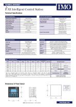
TECHNICAL DATASHEET Input / Output Specifications Pulse Measurement Frequency Measurement There are 4 high-speed inputs of the total DC inputs. There are 2 high-speed outputs of the total DC outputs. Model 10D03, 10B04, 20B05 feature 12-bit Analogue I/O. Model 13C14 features 14/16-bit Analogue I/O. High-speed outputs can be used for PWM and Pulse Train Outputs, currently limited to <10kHz and <65kHz for the 10E24 model. Model 10E14 features a 14/17 bit Analogue I/O. 2 Position Controlled Outputs 1 ON/OFF Setpoint per Output Dimensions & Panel Cutout CUTOUT TOLERANCE TO MEET NEMA STANDARDS IS ±0.005”...
Open the catalog to page 2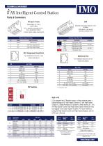
TECHNICAL DATASHEET 3 l AX Intelligent Control Station Ports & Connectors DC Input / Frame Torque rating: 4.5-7 Lb-in (0.50-0.78Nm) DC- is internally connected to I/O V-, but is isolated from CAN VA Class 2 power supply must be used CAN Mounting screw torque rating: 4.5 Lb-in (0.50Nm) SHLD and V+ pins are not internally connected to i3A Primary Power Port Pins Primary Power Port Pins 2 DC- Input Power Supply Ground 3 DC+ Input Power Supply Voltage Signal Description Direction V- CAN Ground - Black - CN L CAN Data Low - Blue IN / OUT SHLD Shield Ground - None -...
Open the catalog to page 3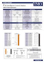
TECHNICAL DATASHEET Jumper Setting Details Note: The Module Setup configuration must match the selected I/O (JP) jumper settings Note: When using JP2 (A1-A4), each channel can be independently configured. WARNING EXPOSURE TO SOME CHEMICALS MAY DEGRADE THE SEALING PROPERTIES OF MATERIALS USED IN THE Tyoo relay PCJ Cover / case & base Mitsubishi engineering Plastics Corp 5010GN6-30 or 5010GN6-30 M8 (PBT) Sealing Material Kishimoto 4616-50K (I part epoxy resin) It is recommended to periodically inspect the relay for any degradation of properties and replace if degradation is found
Open the catalog to page 4
TECHNICAL DATASHEET
Open the catalog to page 5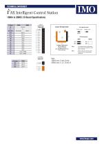
TECHNICAL DATASHEET Jumper Setting Details Location of I/O jumpers (JP1 & JP3) and wiring connectors (J1, J2, J3 & J4) with back cover removed. Negative Logic Note: The Module Setup configuration must match the selected I/O (JP) jumper settings Note: When using JP2 (A1-A2), each channel can be independently configured.
Open the catalog to page 6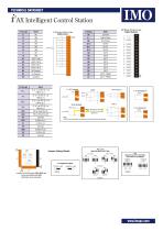
l AX Intelligent Control Station J1 (Orange) ■< Jumper Setting Details Location of I/O jumpers (JP1-JP4) and wiring connectors (J1-J4) with back cover removed. JP1 Digital DC Inputs Positive Logic Negative Logic L°.^> SO> Default JP2& JP3 ANALOG INPUT SETTING T/C/IOOmV RTD (PTIOO) JP4 ANALOG OUTPUT SETTING VOLTAGE OR CURRENT
Open the catalog to page 8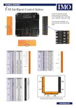
l AX Intelligent Control Station J1 (Orange/Green) For ease of operability, the high density terminals are divided into more manageable pairs of connectors (J1A + J1B, J2A + J2B, J3A + J3B) To ensure proper installation, connector symbols must match as seen below:
Open the catalog to page 10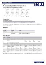
The data registers as follows:- Digital Inputs Digital Outputs Analogue Inputs Analogue Outputs Note: The first four Analogue inputs are mapped to both %AI1-4 and %AI33-36, analogue input channels 5 & 6 are mapped to %AI37 and %AI38 respectively only.Data ValuesThe analogue inputs return data types as follows:- Input Mode 0-20mA, 4-20mA 0-10V, 0-60mV TC, RTD Temperature in °C or °F to 1 decimal place xxx.y °C or °F may be selected in the I/O config section. The value is an integer, the user should divide by 10. Status Register Register Note: For the purposes of the example, the block...
Open the catalog to page 11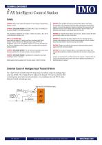
WARNING: Battery may explode if mistreated. Do not recharge, disassemble or dispose of in fire. WARNING: EXPLOSION HAZARD - BATTERIES MUST ONLY BE CHANGED IN AN AREA KNOWN TO BE NON-HAZARDOUS This equipment is suitable for use in Class 1, Division 2, Groups A, B, C and D or Non-hazardous locations only. FOR U.S. & CANADA ONLY Power input and output (I/O) wiring must be in accordance with Class 1, Division 2 wiring methods of the National Electric Code, NFPA70 for installations in the U.S. or as specified in Section 18-1J2 of the Canadian Electric Code for installations within Canada and in accordance...
Open the catalog to page 12All IMO Precision Controls Limited catalogs and technical brochures
 IMO Corporate Brochure
9 Pages
 SolarProduct Range
56 Pages
 Drive 2
6 Pages
 Industrial Power Supplies Range
28 Pages
 Inductive Proximity Switches PB
10 Pages
 VXA Brochure
12 Pages
 Push Buttons
32 Pages
 MCB Brochure
8 Pages
 Din Terminals
64 Pages
 Panel Products
24 Pages
 Solar Installer
12 Pages
 Solar Isolators
32 Pages
 Self Funding Scheme
12 Pages
 HVAC Brochure
12 Pages
 Jaguar Drives
20 Pages
 Terminal Block
68 Pages
 Relays
36 Pages
 Audible Devices
126 Pages
 Solar Cube
4 Pages
 i3 Intelligent Controllers
8 Pages
 BX series
3 Pages
 Remote IO Modules
3 Pages
 Intelligent Control Station
4 Pages
 XGB
XGB5 Pages
 IMO
IMO56 Pages
 Automation Product Range
24 Pages


- LIMING DC power supply
- LIMING AC/DC power supply
- Rectangular housing
- LIMING digital I/O
- Plastic housing
- Single-pole switch
- Wall-mount box
- CE power supply
- LIMING proximity sensor
- LIMING I/O module
- Junction block
- Push-button switch
- Single-output power supply
- Metal housing
- LIMING junction box
- Switching power supply
- Power supply for industrial applications
- Switching relay
- LIMING analog I/O