

High & Medium pressure pumps GA

High & Medium pressure pumps GA
The GA bypass valve is designed for use as a pressure-relief valve in hydraulic systems, oil circulation circuits, and oil firing systems. It is suitable for mineral oils and similar liquids but not for water, steam, or corrosive liquids.
Mode of Function
This direct-acting valve is known for its rapid opening, minimizing pressure surges during sudden flow changes. It includes an automatic hydraulic pressure compensation device to maintain minimal pressure rise within the specified flow rate range. The valve features a throttling screw for fine adjustments, factory-set and typically not requiring further adjustment.
Versions
The GA bypass valve is available in three versions: GAR (threaded pipe connections), GAS (SAE-flanged pipe connections), and GAD (DIN-flanged pipe connections). Each version has specific model codes and specifications.
Material
The valve casing is made of steel for GAR and GAS types, and nodular iron for GAD. Spring casings vary by size, with steel for smaller sizes and nodular iron for larger ones. O-rings are made of Viton rubber, and other parts are steel.
Installation
The valve should be installed close to the unit it protects, with no flow-blocking components in the return line. It can be mounted in any position but must remain filled with liquid for proper damping function. The system should not be pressure tested with water to avoid corrosion or freezing damage.
Type Specification
Details are provided for each type, including ordering codes, nominal pressure, and flow rates. The recommended set pressure is 10% above the system working pressure, with a viscosity range of 2-400 mm²/s and a temperature range of -20°C to +150°C depending on the O-ring material.
Dimensions
Dimensions for valve types GAR, GAS, and GAD are provided, including connection diameters and weights. Counterflange dimensions for GAS are also detailed.
Selection Diagram
The document includes a selection diagram showing valve characteristics at maximum nominally adjustable opening pressure, with pressure rise not exceeding 10% above the set pressure.
Catalog excerpts

Max pressure: 10 MPaMax flowrate: 15 dm 3 /s (900 I/min) Bypass valve type GA is intended for use as a pressure-relief valve in hydraulic systems, oil circulation circuits, oilfiring systems, etc. The valve is intended for mineral oils and liquids with similarproperties and must not be used for water, steam, corrosiveliquids or the like. > Bypass valve type GA is direct-acting and is distinguished by its high speed during the opening process, enablingpressure surges in the event of sudden changes in volumetricflow to be kept at a low level. The valve features a built-in, automatically acting hydraulicpressure compensation device which endeavours to keepthe pressure rise as small as possible within the flow rate range area specified for the valve (cf. pressure rise in re-sponse to increasing flow for a purely spring-loaded valve)During the closing process, the pressure largely coincides with the pressure during the opening process. For fineadjustment of the valve characteristics, the valve is providedwith a throttling screw at the outlet which, upon delivery, is factory set and which does not usually require subsequentadjustment. > The bypass valve type GA is available in the followingversions: GAR with valve casing for threaded pipe connections GAS with valve casing for SAE-flanged pipe connections GAD with valve casing for DIN-flanged pipe connection > Valve casing - steel for types GAR and GAS- nodular iron for type GAD Spring casing - steel for sizes 012, 015, 020, 034- nodular iron for sizes 025, 040, 065, 100, 112 O-rings - Viton rubber Other parts - steel > R = Threaded pipe connectionsS = SAE-flanged pipe connectionsD = DIN-flanged pipe connections Size (size code according to type specification overleaf) Design specification (upon deviation from standard design - 0 indicatesstandard design) Design modification (1 - indicates original design) Valve spring (code according to type specification overleaf)or Special varian t (max. opening pressure determined by the variant) Example: GAS 04001 T040, valve with SAE-flanged connections dia. 40 mm in standard design with spring formax. 4.0 MPa opening pressure. > GA 1102.02 GB size="-3">
Open the catalog to page 1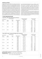
A bypass valve is to be installed in the outlet line as close aspossible to the unit which is to be protected against excessivelyhigh pressure by the valve. No components liable to block the flow and prevent the valve from releasing liquid when the openingpressure has been attained may be installed in the return linefrom the valve. Overflowing liquid should be returned to tank enabling the heat evolved in overflowing to be distributed amongthe largest possible liquid volume. Bypass valve type GA maybe mounted in any position. In order for the damping device incorporated in the valve to function...
Open the catalog to page 2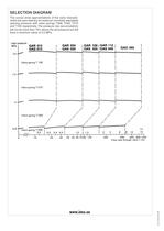
The curves show approximations of the valve characte-ristics set upon delivery at maximum nominally adjustableopening pressure with valve springs T008, T040, T075and T100 respectively. The pressure rise (accumulation) will not be more than 10% above the set pressure but willhave a minimum value of 0.2 MPa. >
Open the catalog to page 4All IMO AB catalogs and technical brochures
 Low pressure pumps Opti Line ACG
16 Pages
 OptiLine ACE Generation4
16 Pages
 Low pressure pumps ACE
16 Pages
 Low pressure pumps ACD
16 Pages
 Low pressure pumps LPD
16 Pages
 T5 valve block
5 Pages
 LPQ pump
16 Pages
 Bypass Valve
4 Pages
 Opti Line ACE4
12 Pages
 IMO OptiLine Pumps
4 Pages
 IMO OptiLine
8 Pages
 Opti Line ACG8 Screw pump
12 Pages
 Low pressure pumps ACF
12 Pages


- Pump
- Industrial pump
- Pump with electric motor
- Lubricant pump
- Oil pump
- Transfer pump
- Hydraulic pump
- High-pressure pump
- Vertical-mount pump
- Vertical pump
- Circulation pump
- Vane pump
- Fuel pump
- Horizontal mount pump
- Lubrication pump
- Magnetic-drive pump
- Booster pump
- Transport pump
- Low-pressure pump
- Pump for maritime applications