18D
1 /4Pages
18D
1 /4Pages
Catalog excerpts
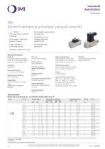
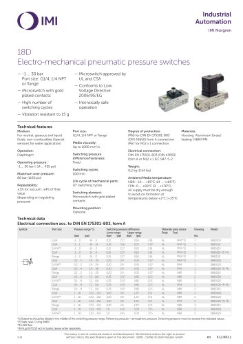
18DElectro-mechanical pneumatic pressure switches — -1 ... 30 bar Port size: G1/4, 1/4 NPT or flange — Microswitch with gold plated contacts — High number of switching cycles — Microswitch approved by ULand CSA — Conforms to Low Voltage Directive 2006/95/EG — Intrinsically safe operation Technical featuresMedium: For neutral, gaseous and liquid fluids, non-combustible (Special versions for water application) Operation: Diaphragm Maximum over pressure: 80 bar (1160 psi) Repeatability: ±3% for vacuum; ±4% of final value (depending on regulating pressure) Port size: G1/4, 1/4 NPF or flange Switching pressure difference/hysteresis: Fixed Life cycle of mechanical parts: 107 switching cycles Switching element: Microswitch with gold plated contacts Degree of protection: IP65 for DIN EN 175301-803 (DIN 43650) form A connection IP67 for M12 x 1 connection Electrical connection: DIN EN 175301-803 (DIN 43650) form A or M12 x 1 IEC 947-5-2 Air supply must be dry enough to avoid ice formation at temperatures below +2°C (+35°F) Housing: Aluminium (brass) Sealing: NBR/FPM Mounting position: Optional Symbol Port size Pressure range *1) Switching pressure difference Materials press sensor Drawing Model Lower range Upper range Body Seal *1) Setpoints should be ideally in the middle of the switching pressure range. Reference pressure = atmospheric pressure. Switching pressure must not exceed the indicated values. *2) Static seal: O-ring (NBR) *4) Plug 0570110 not included, please order separately. Our policy is one of continued research and development. We therefore reserve the right to amend, without notice, the specifications given in this document. (1998 - 5249e) © 2024 Norgren GmbH
Open the catalog to page 1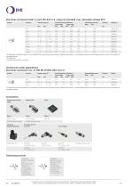
Electrical connection M12 x 1 nach IEC 947-5-2 - plug not included, max. allowable voltage 30 V Port size Pressure range *1) Switching pressure difference Lower range Upper range (bar) (psi) (bar) (psi) Materials press sensor Drawing Body Seal *1) Setpoints should be ideally in the middle of the switching pressure range. Reference pressure = atmospheric pressure. Switching pressure must not exceed the indicated values. *3) Switching function reversed Versions for water applications Electrical connection acc. to DIN EN 175301-803, form A Symbol Port size Pressure range *1) Switching pressure difference...
Open the catalog to page 2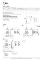
Switching capacityCommutator with gold plated contacts Current Load type *2) U min Max. permissible persistent current Imax [A] at U *1) (UL & CSA) Electrical life-time Reference number: 20/min, Reference temperature: +20°C. *1) Higher currents (5 A max) will cause a reduction of the durability of the micro-switch contacts. Futhermore additional measures has to be taken to fulfil the EMV regulation 2004/108/EG by the manufacturer *2) Spark quenching/overload protection will be necessary using inductive loads. Recommended circuitSpark quenching and EMV intrinsically safe 1. Quick diode (D) with...
Open the catalog to page 3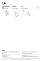
Dimensions in mm Projection/First angle Pressure port reducing nipple Surge damper Model: 0574767 (brass) 0550083 (stainless steel) Model: 0574773 (brass) 0553258 (stainless steel) G1/4 Warning These products are intended for use in industrial compressed air systems only. Do not use these products where pressures and temperatures can exceed those listed under »Technical features/ data«. Before using these products with fluids other than those specified, for non-industrial applications, life-support systems or other applications not within published specifications, consult Norgren Ltd. Through...
Open the catalog to page 4Archived catalogs
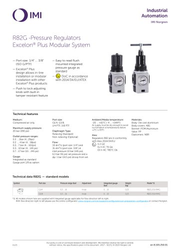 R82G
R82G7 Pages
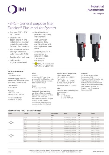 F84G
F84G10 Pages
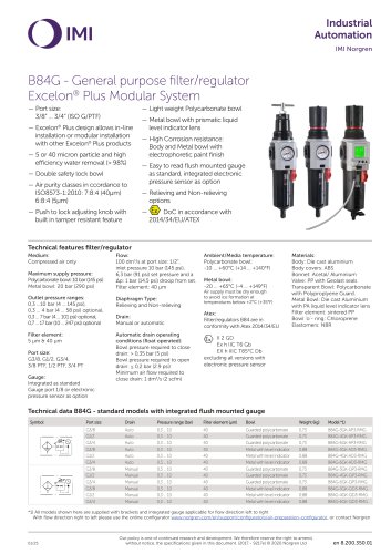 B84G
B84G11 Pages
 Industrial Automation
16 Pages
 RA/802080/M/80
35 Pages
 Safe Systems
12 Pages
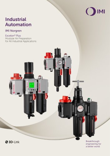
 Excelon® Plus
16 Pages
 Express Catalogue
228 Pages
 ISO Standard Cylinders
16 Pages
 Rail catalogue 2017
378 Pages
 Fittings and Accessories
115 Pages
 Mobile Pneumatics Catalogue
244 Pages
 Digest of IMF' manufacturing
8 Pages


- Valve
- Fitting
- Manual valve
- Control valve
- Stainless valve
- Screw-in fitting
- Pneumatic valve
- Pneumatic fitting
- Electrically operated valve
- Threaded valve
- Metal fitting
- Regulating valve
- On/off valve
- Flap valve
- Check valve
- Stainless fitting
- Gas solenoid valve
- NC solenoid valve
- 2-way solenoid valve
- Direct-operated solenoid valve