
- Catalogs
- Imao Corporation
- Spring Clamps

Spring Clamps
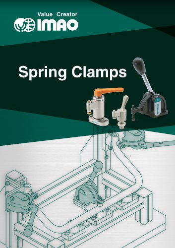
Spring Clamps
The document outlines various clamps and their components, specifying materials such as S45C steel, SCM440 steel, and phenolic plastic. It details finishes like black oxide and chrome plating, and provides part numbers (e.g., QLSND-AN10, QLSNS28-05) along with dimensions and weights.
Procedures:
It includes instructions for installing angular adaptors and using snap clamps, explaining the recommended clamping position for handles and the operation of clockwise (CW) and counterclockwise (CCW) clamping types.
Norms and Recommendations:
Clamping forces and handle operating loads may vary by ±20%. A wrench of nominal size 9 is recommended for handle removal. Specific clamping spindles are advised to protect workpieces.
Key Features:
Clamps are spring-loaded for consistent force, with extended clamping-bar projection ranges. A handle click indicates clamping completion. A snap-on system is used for double locking.
Data Summary:
Tables provide measurements for clamping strokes, operating loads, and clamping forces. For instance, the QLSNS28-05 has a clamping force of 370N and a handle operating load of 50N.
Installation and Usage:
Instructions for face and back mounting are included, with notes on using cap screws. Examples of vertical clamping applications and mounting clamping bars are provided.
Technical Information:
Details on allowable load and accuracy of clamping bars are provided, including an allowable attachment weight of 500g and deflection of ±0.05. Rotation accuracy is specified as ±0.1° under no load.
Catalog excerpts

Value Creator
Open the catalog to page 1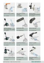
SPRING SWING CLAMPS MINI SPRING SWING CLAMPS VERTICAL-HANDLE HOLD-DOWN SNAP CLAMPS(Mini) VERTICAL-HANDLE HOLD-DOWN SNAP CLAMPS ANGLE ADAPTOR PUSH-PULL SNAP CLAMPS CLAMPING SPINDLES THRUST CLAMPS THRUST CLAMPS (Vertical) CLAMPING BARS PRECISION THRUST CLAMPS
Open the catalog to page 2
Value Creator
Open the catalog to page 3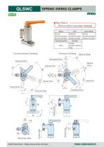
SPRING SWING CLAMPS ★Key Point -[_Click to confirm consistent clamping Body CAD Download : https://www.imao.com/en/ imnocoRPORATion
Open the catalog to page 4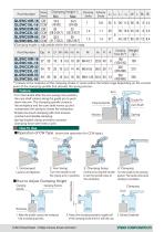
*)Clamping height is adjustable within the listed range. Part Number **) Values at the midpoint of the clamping stroke. It varies within the listed range depending on the contact point of the clamping spindle that decides the spring tension. Feature ■ Turn the handle after the arm swings into position, the cam shaft rotates along the guide pin to push down the arm. The clamping spindle contacts the workpiece and the cam shaft moves up and compresses the spring to clamp the workpiece. ■Simple one-touch clamping with click ensures constant and reliable clamping. ■Spring-loaded clamp provides constant...
Open the catalog to page 5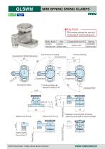
MINI SPRING SWING CLAMPS Stainless Steel ★Key Point Mini swing clamps for vertical clamping of small workpieces Body, Knob Arm Clamping Spindle, Guide Pin Spring SUS303 SUS304L SUS304WPB Stainless steel stainless steel stainless steel stainless steel 2-Counterbored Slots for M3 Socket Head Cap Screws Counterclockwise Clamping Unclamping Position Clamping Position Mounting Hole Details Clamping Position *) The knob operating angle required for clamping is 160°. Unclamping Position Clamping Height Clamping Spindle Across Flats 7 Above-Arm Fixing Below-Arm Fixing 16 **) Depending on its mounting...
Open the catalog to page 6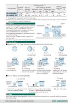
***) Clamping height is adjustable within the listed range. ****) The listed value is the clamping force at the midpoint of the clamping stroke. The range indicates variation in clamping force due to spring compression. Feature ■A single knob operates both the arm swing and clamping motions. Turn the knob to swing the arm into position, then continue turning to lower the arm. When the clamping spindle contacts the workpiece, the internal spring compresses to apply clamping force. ■Simple one-touch clamping with a click ensures constant and reliable clamping. ■The built-in spring provides consistent...
Open the catalog to page 7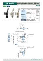
VERTICAL-HANDLE HOLD-DOWN SNAP CLAMPS (Mini) HIMO (Black Oxide Finish) (Stainless Steel) (Electroless Nickel Plated) Type
Open the catalog to page 8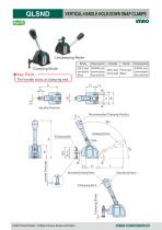
QLSND VERTICAL-HANDLE HOLD-DOWN SNAP CLAMPSimno Unclamping Mode Clamping Mode ★Key Point The handle clicks at clamping end. Body CAD Download : https://www.imao.com/en/ imnocoRPORATion
Open the catalog to page 10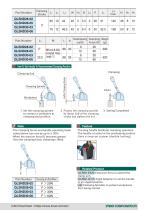
■The long handle facilitates clamping operation. ■The handle is locked at the unclamping position. ■Uses a snap-on system (double locking) I QLSND-EX20 I Extension Arms to extend the clamp arm. I QLSND-AN10 I Angle Adaptors to set the handle in an angled position. I UB I Clamping Spindles to protect workpieces from being marred.
Open the catalog to page 11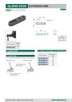
Dedicated for Snap Clamps EXTENSION ARMmo Body S45C steel Black oxide finish Part Number Supplied With Clamping Forces Generated in Use of Extension Arms Hex. socket head setscrew M5X0.8-14L X2 pcs.
Open the catalog to page 12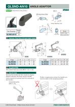
RettS Part Number Dimensions of Snap Clamps with Angular Adaptor Installed Supplied With Hex.socket head cap screw M6X1-12L X 1pc. Remove the handle and then install an Angular Adaptor between the b°dy and the handle. perfect in applications where the handle can (Use a wrench of nominal size 9 for removal of not be turned to the clamping position.
Open the catalog to page 13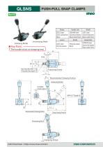
QLSNS PUSH-PULL SNAP CLAMPSHIMO ★ Key Point ->. CAD Download : https://www.imao.com/en/ imnocoRPORRTion
Open the catalog to page 14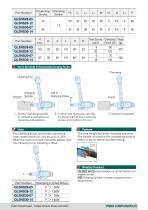
■The long handle facilitates clamping operation. ■The handle is locked at the unclamping position. ■Uses a snap-on system (double locking) ■ | QLSND-AN10 I Angle Adaptors to set the handle in an angled position. ■ ■ UB I Clamping Spindles to protect workpieces from being marred.
Open the catalog to page 15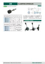
CLAMPING SPINDLES Installation example
Open the catalog to page 16
Value Creator
Open the catalog to page 17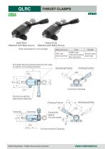
THRUST CLAMPS Light-Duty (Marked with Blue Arrow) Heavy-Duty (Marked with Black Arrow) Note: Clamping bar is not included. SCM415 steel S45C steel Phenolic plastic Carburized-hardened Black oxide finish Black matte Black oxide finish M-4 Handle-Mounting Holes(provided every 90° angle) (4 options of mounting position) L Clamping Position Unclamping Position Clockwise Clamping 2-d Blue Arrow for Light-Duty Black Arrow for Heavy-Duty Clamping Position Projection Range QLRCS (To be ordered separately) Clamping Stroke Counterclockwise Clamping Unclamping Positi
Open the catalog to page 18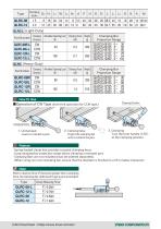
Part Number Clamping Direction Allowable Operating Load Clamping Force Weight (N) (kN) (g) Clamping-Bar Projection Range Part Number Clamping Direction Allowable Operating Load Clamping Force Weight (N) (kN) (g) Clamping-Bar Projection Range ■Operation of CW Type (Invert the operation for CCW type.) Clamping Position 120° Unclamping Position 1. Unclamped Load or unload a part. 2. Clamping Setup Project the clamping bar until it contacts the part. 3. Clamping Turn the lever handle (120°) to the clamping position. Feature ・Spring-loaded clamp that provides constant clamping force. ・Long clamping-bar...
Open the catalog to page 19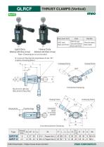
THRUST CLAMPS (Vertical) Body/Lever Arm Light-Duty Heavy-Duty(Marked with Blue Arrow) (Marked with Black Arrow) Note: Clamping bar is not included. QLRCS (To be ordered separately) Counterclockwise Clamping
Open the catalog to page 20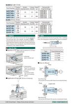
QLRCF-Ll (Light-Duty) ■ Can be used in both vertical and horizontal clamping applications. ■The horizontal style is also available. (see page for I QLRC I ) ■ Spring-loaded clamp that provides constant clamping force. ■ Long clamping-bar projection range allows clamping a recessed part. (When using your own clamping bar, ensure that the diameter is finished to a h9 or better tolerance) How To Use When a reaction force (F) becomes greater than a clamping force, the clamping bar slides back to get a part unclamped. 2. Clamping Setup Project the clamping bar until it contacts the part. 3. Clamping...
Open the catalog to page 21
IRlflO CORPORATOR
Open the catalog to page 22
Value Creator
Open the catalog to page 23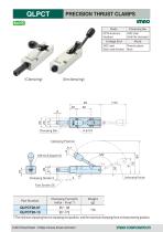
PRECISION THRUST CLAMPS Body Part Number *) The minimum clamping force at clamping end position, and the maximum clamping force at clamp starting position.
Open the catalog to page 24All Imao Corporation catalogs and technical brochures
 Robot Integration Solutions
17 Pages
 Pneumatic Flex Locators
24 Pages
 One Touch Fasteners
160 Pages
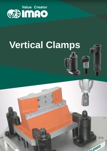 Vertical Clamps
20 Pages
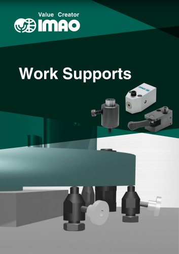 WORK SUPPORTS
31 Pages
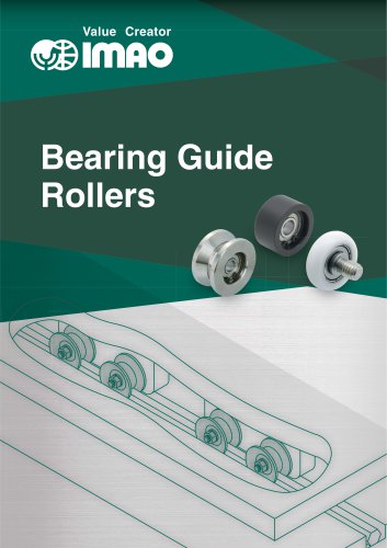 Bearing Guide Rollers
35 Pages
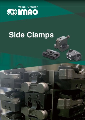 Side Clamps
27 Pages
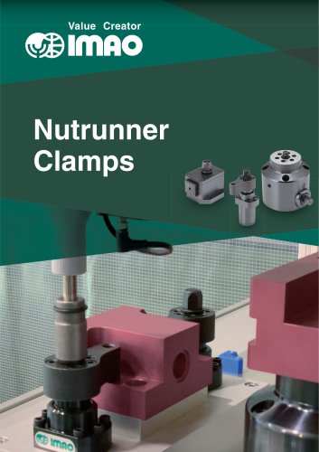 NUTRUNNER CLAMPS
24 Pages
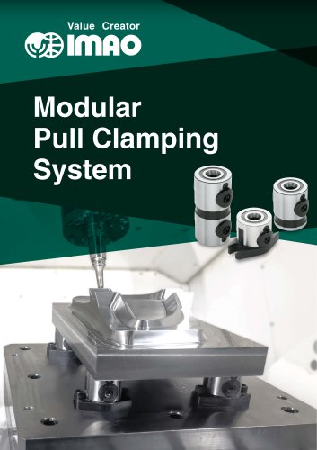 Modular Pull Clamping System
41 Pages
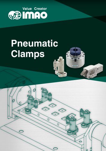 PNEUMATIC CLAMPS
46 Pages
 Machinable Collet Clamps
48 Pages
 PNEUMATIC CLAMPING FASTENERS
16 Pages
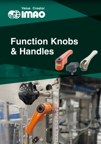 Function Knobs & Handles
22 Pages
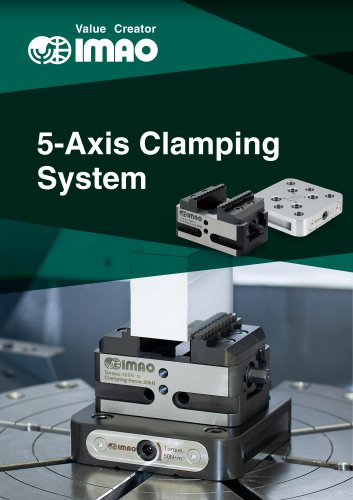 5-Axis Clamping Systems
15 Pages
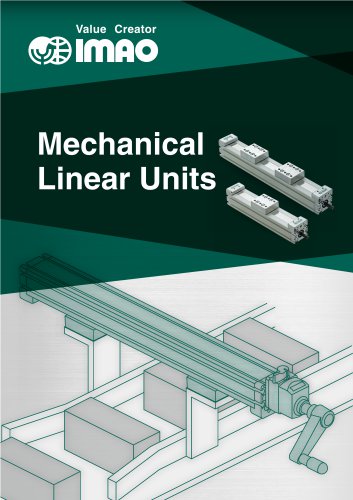 MECHANICAL LINEAR ACTUATORS
36 Pages
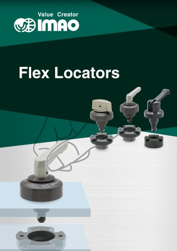 Flex Locators
46 Pages
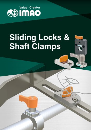 Sliding Locks & Shaft Clamps
59 Pages
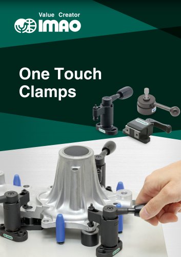 ONE TOUCH CLAMPS
68 Pages
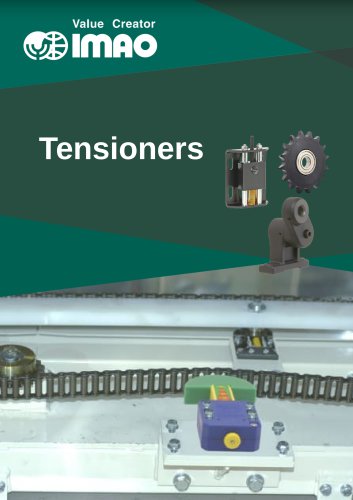 TENSIONERS
45 Pages
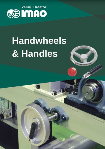 HANDWHEELS & HANDLES
31 Pages
 SCREWS & NUTS
13 Pages
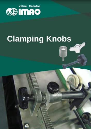 CLAMPING KNOBS
22 Pages
 LOCATING PARTS
15 Pages
 GRIPPERS
28 Pages