
- Catalogs
- Imao Corporation
- Sliding Locks & Shaft Clamps

Sliding Locks & Shaft Clamps
1 /58Pages
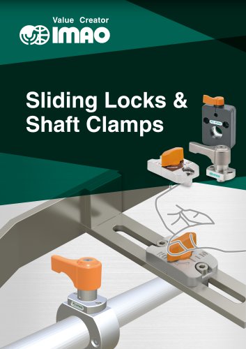
Sliding Locks & Shaft Clamps
1 /58Pages
Catalog excerpts
Value Creator Sliding Locks & Shaft Clamps
Open the catalog to page 1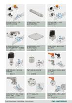
SLIDING LOCKS FOR SLOTTED HOLE RISER PLATES FOR SLIDING LOCK SLIDING LOCKS FOR SQUARE BAR SLIDING LOCKS FOR SQUARE BAR WITH HANDLE RISER PLATES FOR SLIDING LOCK ONE-TOUCH INDEXING CLAMPS ONE-TOUCH INDEXING CLAMPS TAPERED BUSHINGS ONE TOUCH PUSH LOCK CLAMPS HEAVY DUTY ONE TOUCH PUSH LOCK CLAMPS SHAFT COLLARS ONE-TOUCH PUSH LOCK UNITS
Open the catalog to page 2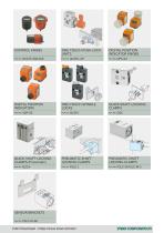
CONTROL KNOBS ONE-TOUCH PUSH LOCK UNITS DIGITAL POSITION INDICATOR KNOBS DIGITAL POSITION INDICATORS ONE-TOUCH SPINDLE LOCKS QUICK SHAFT-LOCKING CLAMPS QUICK SHAFT-LOCKING CLAMPS (Pneumatic) PNEUMATIC SHAFT LOCKING CLAMPS PNEUMATIC SHAFT LOCKING CLAMPS SENSOR BRACKETS Part No. PSLC-M-SB
Open the catalog to page 3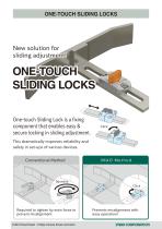
ONE-TOUCH SLIDING LOCKS New solution for sliding adjustment! ONE-TOUCH SLIDING LOCKS One-touch Sliding Lock is a fixing component that enables easy & secure locking in sliding adjustment. This dramatically improves reliability and safety in set-ups of various devices. Conventional Method IMAO Method Squeeze Click Required to tighten by main force to prevent misalignment. CAD Download : https://www.imao.com/en/ Prevents misalignment with easy operation!
Open the catalog to page 4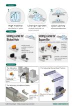
High Visibility Easy-to-read ON/OFF position Leveling of Operation The knob clicks when it is locked/unlocked. Sliding Locks for Slotted Hole Secure Locking Secure locking with wedge structure. Sliding Locks for Square Bar Can be used with commercially-available square bars Knob is available in plastic or metal. Plastic knob is available in black or orange. Metal knob is resistant to damage. Handle is accessible from the side even in tight space. For Adjusting Camera Position For Adjusting Stamp Base Position Sliding Locks For Slotted Hole QCSL For Adjusting Workpiece Guide Sliding Locks For...
Open the catalog to page 5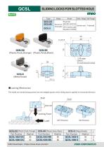
SLIDING LOCKS FOR SLOTTED HOLE iQCSL-OGl (Plastic Knob, Orange) CAD Download : https://www.imao.com/en/ imnocoRPORATion
Open the catalog to page 6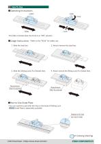
The slide is locked when the knob is at “ON” position. ■Usage Instructions * Refer to the “Note” for safety use. 1. Slide the steel bar. 3. Slide the Sliding Locks For Slotted Hole. 4. Attach/remove the Sliding Locks For Slotted Hole. ■How to Use Scale Plate ・You can read the scale with the line on the body of Sliding Lock. ・ ES1N Scale Plate is separately available. Reading Line for Scale (on each side) Continuing on Next Page CAD Download : ht
Open the catalog to page 7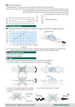
・Usable Materials: Flat bar (JIS h14 grade) made of SS400, S45C or SUS304 etc. ・Machining of slotted hole: Recommended tolerance of the slotted hole to prevent chattering is shown as below. For more accurate sliding, machine the slotted hole to fit the dimension of 10mm(-0.05 to 0) on the bottom of Sliding Locks. Remove the burr around the slotted hole to ensure secure locking. Thickness Reference : QCSLSP “How To Use” Performance Curve ■The displacement of steel bar by axial load (Static load from single direction) 1.0 LoadN Note: The above data is for a flat bar made of SUS304 stainless steel,...
Open the catalog to page 8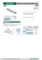
RISER PLATES FOR SLIDING LOCK Part Number Can be used for various steel thicknesses by attaching the Riser Plates (to be ordered separately).
Open the catalog to page 9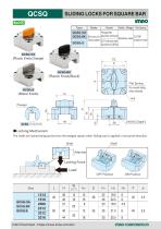
SLIDING LOCKS FOR SQUARE BAR Type (Plastic Knob,Orange) IQCSQ-Sl (Metal Knob) (Plastic Knob,Black) The shafts are locked being pushed into the wedged spaces when sliding load is applied in horizontal direction.
Open the catalog to page 10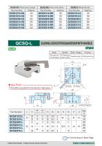
QCSQ-L SLIDING LOCKS FOR SQUARE BAR WITH HANDLE imno Body [ The handle is accessible from the side even in tight spaces. Part Number Continuing on Next Page
Open the catalog to page 11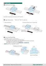
■Operating Instructions The slide is locked when the knob is at “ON” position. ■Usage Instructions * Refer to the “Note” for safety use. 2. Slide the Sliding Locks For Square Bar. ■How to Use Scale Plate ・Scale plate can be put on the steel bar. Note: Fit scale plate inside the slot in the figure below. Putting scale plate outside the slot cause interference between scale plate and Sliding Lock, and this may cause failure. Scale plate can not be put on the QCSQ1212 or QCSQ1616 . ・ ES1N Scale Plate is separately available. Reading Line for Scales Slot for Scale Plates
Open the catalog to page 12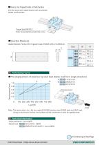
Can be used with attachments such as pointer plates and brackets. ■ Steel Bar Materials Usable Materials: Flat bar (JIS h14 grade) made of SS400, S45C or SUS304 etc. Performance Curve■The displacement of steel bar by axial load (Static load from single direction) A: I QCSQ 11212,1616 B: I QCSQ I 2509,2512 IQCSQ I 3212,3216 Note: The above data is for a flat bar made of SUS304 stainless steel, SS400 steel and S45C steel. Using an aluminum flat bar, the surface will be scratched or dent by applied load. ■ Heat resistance : Up to 90°C ■Rated load : IQCSQ I 1212,1616 : 500N
Open the catalog to page 13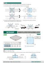
The following conditions may cause displacement increasing or misalignment. 1. Use under slippage or chattering caused by vertical or horizontal loads 2. Use with a clearance between the steel bar and 3. Use under excess shock or vibration the base when the Sliding Locks at "ON" position. RISER PLATES FOR SLIDING LOCK Body How To Use■ How to Use Riser Plate Riser Plates (to be ordered separately) can lift the steel bar to create a clearance between the steel bar and the base.
Open the catalog to page 14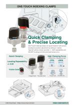
Quick Clamping & Precise Locating One-Touch Indexing Clamps are quick fasteners with precise locating for position adjustment by sliding or rotation. Tapered surface contact provides +/- 0.05 repeatability and ON/OFF marking and click eliminate human error. Quick Clamping High Clamping Force Clamping Force Allowable Axial Load Locating Repeatability: +/- 0.05 Visible Safety Flanged Style Threaded Style Flanged Style
Open the catalog to page 15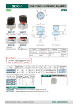
ONE-TOUCH INDEXING CLAMPS (Without Spring Pressure) Spring Pressure) QCIC05F26|: 3 of socket-head cap screws(Stainless Steel), M3X0.5-6L QCIC07F32|: 3 of socket-low-head cap screws(Stainless Steel), M4X0.7-8L QCIC-TB Size TAPERED BUSHINGS
Open the catalog to page 16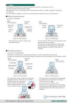
Feature ・Clamping by the tapered pin allows locating and fixing with no clearance at once. ・Use with the dedicated tapered bushing. ・ON/MID/OFF mark on the body and the knob position allow to visually recognize clamping or unclamping. ・The red indicator appears to show the unclamping state when the knob is in OFF position. ■Without Spring Pressure Knob Knob 2 positions of ON/OFF (OFF (OFF position) position) Knob Knob Mounting Mounting (OFF position) (OFF position) screws screws Mounting Moving Mounting Moving screws part part screws Moving Moving part part Knob Knob Indicator Indicator (ON (ON...
Open the catalog to page 17All Imao Corporation catalogs and technical brochures
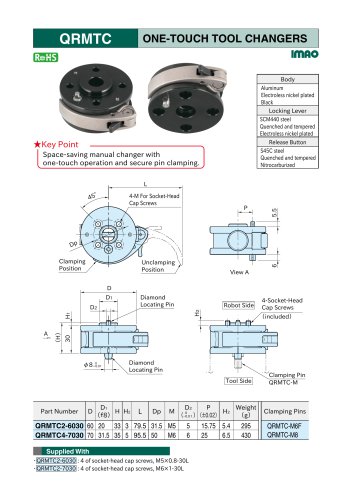 One-Touch Tool Changers
3 Pages
 Pneumatic Flex Locators
24 Pages
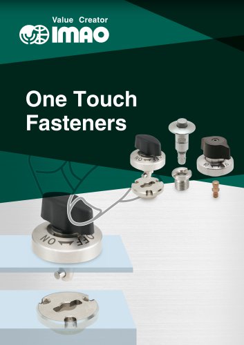 One Touch Fasteners
160 Pages
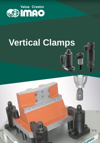 Vertical Clamps
20 Pages
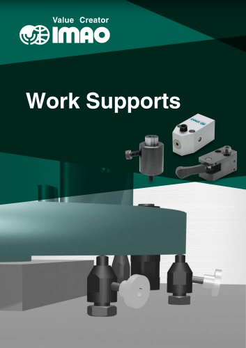 WORK SUPPORTS
31 Pages
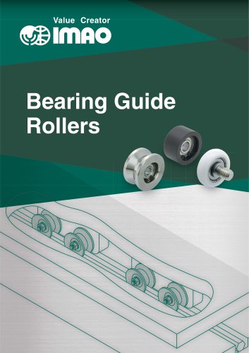 Bearing Guide Rollers
35 Pages
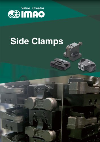 Side Clamps
27 Pages
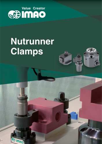 NUTRUNNER CLAMPS
24 Pages
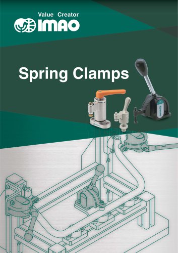 Spring Clamps
23 Pages
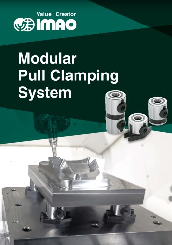 Modular Pull Clamping System
41 Pages
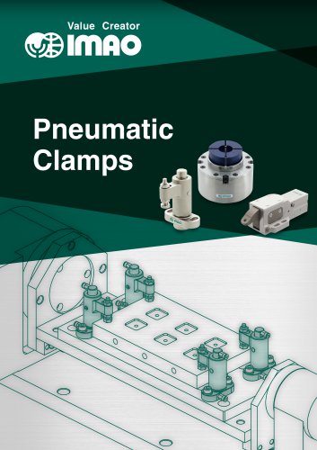 PNEUMATIC CLAMPS
46 Pages
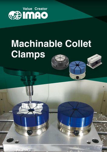 Machinable Collet Clamps
48 Pages
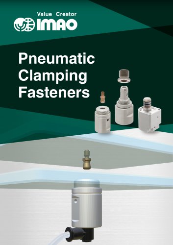 PNEUMATIC CLAMPING FASTENERS
16 Pages
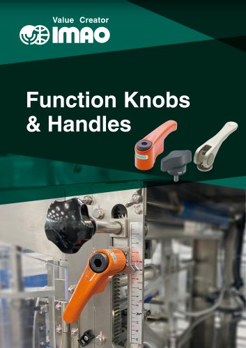 Function Knobs & Handles
22 Pages
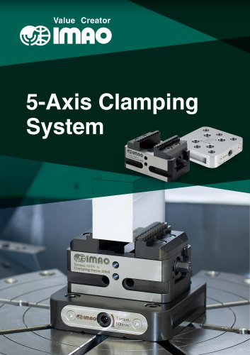 5-Axis Clamping Systems
15 Pages
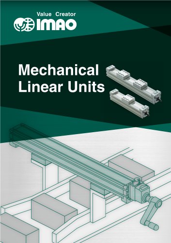 MECHANICAL LINEAR ACTUATORS
36 Pages
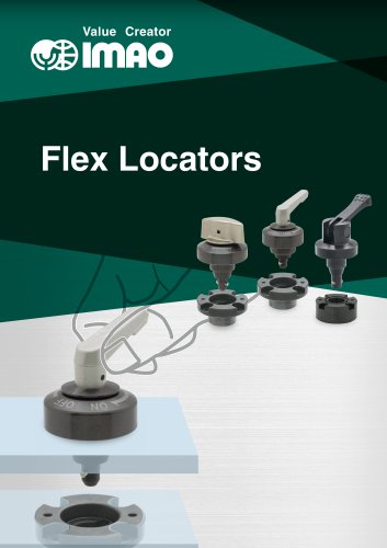 Flex Locators
46 Pages
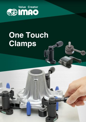 ONE TOUCH CLAMPS
68 Pages
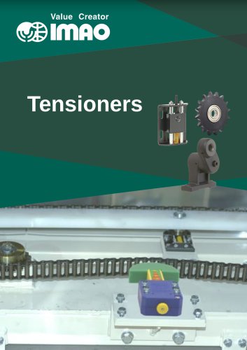 TENSIONERS
45 Pages
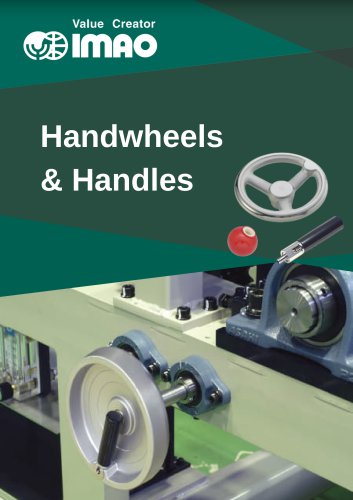 HANDWHEELS & HANDLES
31 Pages
 SCREWS & NUTS
13 Pages
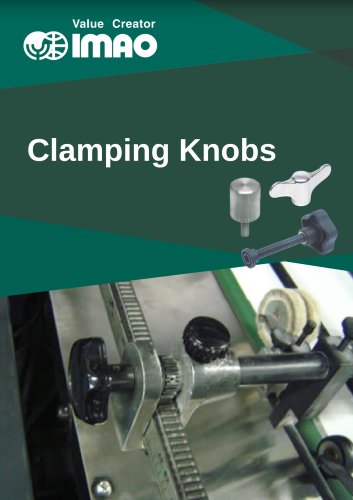 CLAMPING KNOBS
22 Pages
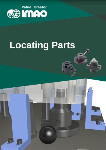 LOCATING PARTS
15 Pages
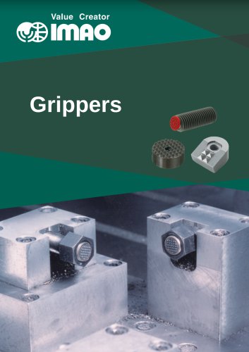 GRIPPERS
28 Pages